

-
Products -PCBA Manufacturing RF Connectors RF Cable Assemblys Embedded Antennas External Antennas GNSS Positioning Solutions
RF Connectors

RF Cable Assemblys
Embedded Antennas
External Antennas
GNSS Positioning Solutions


 Language


Language

Model: TX-G082
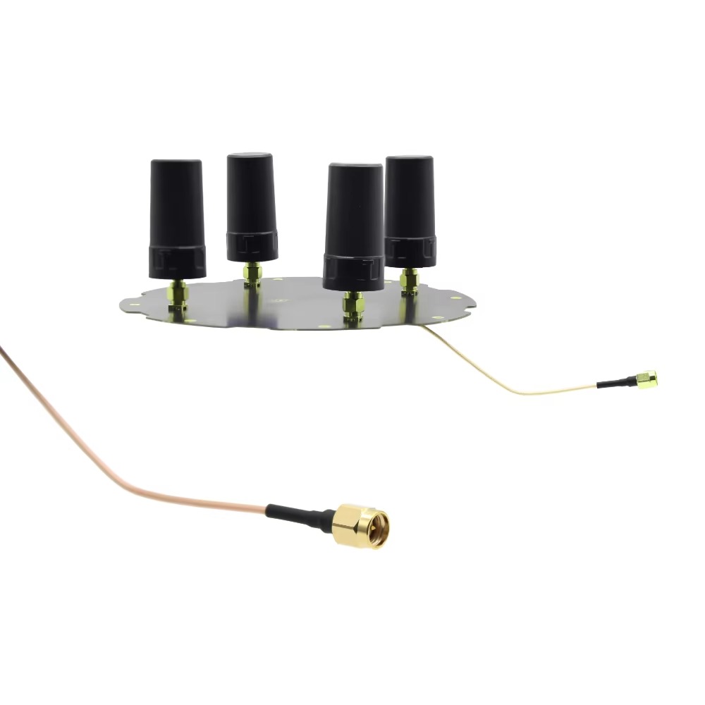
The TOXU TX-G082 is a four-element multi-band active GNSS antenna array designed for compatible navigation systems requiring multi-constellation and multi-frequency satellite-signal reception. It supports specified GPS, BDS, GLONASS, Galileo, and L-band signals and integrates four RHCP antenna elements on a compact circular platform.
● Multi-Constellation Signal Support:Supports specified BDS B1I/B2a/B3I, GPS L1/L2/L5C, GLONASS G1/G2, Galileo E1/E2/E5a/E5b/E6, and L-band signals.
● Four-Element Array Architecture:Four antenna elements provide multiple RF signal channels for connection to a compatible multi-channel GNSS signal-processing system.
● Active 34±2dB Amplification:Each active antenna channel incorporates a low-noise amplifier with specified gain of 34±2dB.
● RHCP Signal Reception:The antenna elements adopt right-hand circular polarization for reception of compatible satellite-navigation signals.
● Wide 3–12V DC Operation:The active circuits operate from 3.0–12V DC, supporting integration with different compatible receiver platforms.
● Compact Circular Platform:The array measures no more than Ø175 × 75mm and uses customizable SMA female output interfaces.
The TOXU TX-G082 is a four-element multi-band active GNSS antenna array developed for compatible navigation and signal-processing systems requiring multiple synchronized antenna inputs.
The array supports specified BDS B1I, B2a, and B3I signals; GPS L1, L2, and L5C signals; GLONASS G1 and G2 signals; Galileo E1, E2, E5a, E5b, and E6 signals; and compatible L-band signals.
Four right-hand circularly polarized antenna elements are arranged on a circular platform. Each antenna channel incorporates an active low-noise amplifier and provides an independent RF output for connection to compatible multi-channel GNSS processing equipment.
The specified gain is greater than 2.0dBi for an individual antenna element and greater than 5.0dBi for the array. Isolation between the antenna elements is specified at no less than 15dB.
The integrated low-noise amplifier provides 34±2dB gain, a noise figure of no more than 1.5dB, output VSWR below 2.0, and in-band flatness of ±2dB. Each active channel operates from 3.0–12V DC and consumes no more than 35mA.
The antenna array measures no more than Ø175 × 75mm. The standard RF output is specified as SMA female and can be customized according to receiver-interface and cable requirements.
The TX-G082 is an antenna array only. Adaptive processing, interference suppression, position calculation, RTK correction handling, navigation output, and other system functions must be performed by compatible external receiver and signal-processing hardware.
Four-Element GNSS Array
Four independently connected antenna elements provide the multiple RF channels required by compatible GNSS array-processing systems.
Multi-Constellation Compatibility
Supports the specified GPS, BDS, GLONASS, Galileo, and L-band satellite-signal frequencies listed in the technical specification.
Multi-Frequency Signal Reception
The wide signal coverage supports compatible receivers designed for multi-band satellite-navigation and correction-service applications.
Greater Than 5.0dBi Array Gain
The specified maximum array gain is greater than 5.0dBi, while the maximum gain of an individual antenna element is greater than 2.0dBi.
34±2dB Active Amplification
Each active channel incorporates a low-noise amplifier to strengthen received satellite signals before transmission to the connected processing equipment.
Low Noise Figure
A specified noise figure of no more than 1.5dB supports low-noise amplification within the supported operating bands.
RHCP Antenna Elements
The four antenna elements use right-hand circular polarization for reception of compatible satellite-navigation signals.
Element Isolation of at Least 15dB
Isolation between the antenna elements is specified at no less than 15dB to support independent multi-channel RF signal acquisition.
360° Horizontal Coverage
The array provides specified 360-degree horizontal-plane coverage when integrated and installed under suitable operating conditions.
Wide DC Input Range
The active circuits operate from 3.0–12V DC, allowing integration with different compatible receiver and processing platforms.
Customizable RF Output
The standard output is specified as SMA female, with connector and cable configurations available for evaluation according to project requirements.
| TOXU Model | TX-G082 |
| Product Type | Four-Element Multi-Band Active GNSS Antenna Array |
| BDS Signals | B1I / B2a / B3I |
| GPS Signals | L1 / L2 / L5C |
| GLONASS Signals | G1 / G2 |
| Galileo Signals | E1 / E2 / E5a / E5b / E6 |
| Additional Signal Support | L-Band |
| Number of Antenna Elements | 4 |
| Nominal Impedance | 50 Ohm |
| Maximum Gain of Individual Element | >2.0dBi |
| Maximum Array Gain | >5.0dBi |
| Array Axial-Plane Coverage Angle | +50° as Specified |
| Roll-Off Factor, 90° to 40° | >6dB |
| Polarization | RHCP |
| Axial Ratio of Individual Element at Zenith | ≤2dB |
| Axial Ratio of Array at Zenith | ≤2dB |
| Horizontal-Plane Coverage Angle | 360° |
| Isolation Between Antenna Elements | ≥15dB |
| Operating Voltage | 3.0–12V DC |
| Low-Noise Amplifier Gain | 34±2dB |
| Output VSWR | <2.0 |
| Operating Current | ≤35mA per Active Channel |
| Noise Figure | ≤1.5dB |
| In-Band Flatness | ±2dB |
| Overall Dimensions | ≤Ø175 × 75mm |
| RF Output Interface | SMA Female, Customizable |
| Specified Weight | 146g × 2, as Stated in the Supplied Specification |
| Operating Temperature | -40°C to +80°C |
| Storage Temperature | -45°C to +85°C |
| Relative Humidity | 95% Non-Condensing |
The following product drawing shows the principal dimensions and physical configuration of the TX-G082 antenna array.
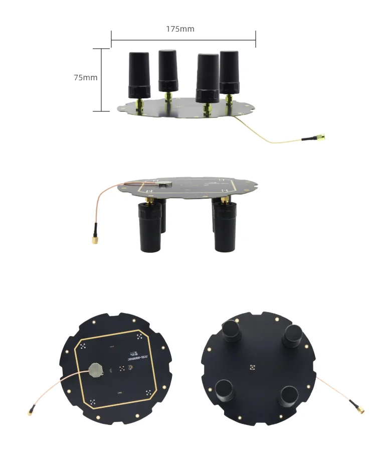
The circular antenna platform has a specified maximum diameter of 175mm and a maximum overall height of 75mm.
Four cylindrical antenna elements are distributed around the circular platform. The RF output cable and connector should be positioned without excessive bending, pulling, or contact with sharp equipment edges.
Confirm the latest controlled mechanical drawing, mounting-hole positions, cable orientation, connector configuration, and installation clearance before enclosure design or volume production.
• Multi-Channel GNSS Navigation Systems
• UAV Navigation Equipment
• Unmanned Vehicle Navigation Systems
• Robotics and Autonomous Platforms
• GNSS Signal-Monitoring Equipment
• Multi-Antenna Navigation Terminals
• Industrial Positioning Equipment
• Research and Test Platforms
• Compatible GNSS Array-Processing Systems
• OEM Navigation Hardware Integration
The TX-G082 must be connected to a compatible multi-channel GNSS receiver or array signal-processing system. A standard single-antenna GNSS receiver cannot independently use the complete four-element array architecture.
Each antenna channel requires a compatible 50-ohm RF input and suitable DC bias power. The specified active-circuit operating voltage is 3.0–12V DC, with current consumption of no more than 35mA per active channel.
Before integration, confirm the receiver model, number of RF input channels, supported satellite frequencies, antenna-bias voltage, available bias current, connector type, RF cable configuration, and array-processing capability.
The standard output interface is specified as SMA female and can be customized. Confirm the required connector gender, cable type, cable length, and equipment-side interface before ordering.
The four RF channels must be correctly identified and connected according to the final channel definition. Cable routing, electrical length, connector consistency, and installation orientation may affect system-level processing performance.
Install the antenna array where it has the clearest practical sky view. Keep the array away from large metal obstructions, motors, switching power supplies, high-power transmitters, and other possible sources of signal blockage or electromagnetic interference.
Final performance depends on the connected receiver, array-processing algorithm, RF-channel consistency, installation structure, cable loss, bias-power quality, equipment enclosure, operating environment, and satellite visibility.
Sample testing with the actual receiver, processing hardware, installation platform, and complete operating software is required before volume production.
TOXU supplies GNSS antennas, multi-element antenna arrays, communication antennas, RF cable assemblies, connectors, GNSS modules, receiver boards, and integrated RF hardware for equipment manufacturers and system integrators.
Our engineering team supports satellite-frequency selection, receiver compatibility evaluation, antenna-bias confirmation, connector and cable matching, installation analysis, RF testing, sample verification, and customized antenna-array development.
TOXU can also support matching RF cable assemblies, GNSS receiver modules, positioning boards, and system-integration services according to the customer's equipment architecture.
With IATF16949 and ISO9001-certified manufacturing capabilities, TOXU supports prototype verification, customized RF interconnections, product inspection, OEM requirements, and stable volume-production delivery.
Q: How many antenna elements does the TX-G082 include?
A: It incorporates four independently connected active GNSS antenna elements.
Q: Which satellite signals does it support?
A: The supplied specification lists BDS B1I/B2a/B3I, GPS L1/L2/L5C, GLONASS G1/G2, Galileo E1/E2/E5a/E5b/E6, and L-band signals.
Q: Is the TX-G082 an active antenna array?
A: Yes. Each active channel incorporates a low-noise amplifier with specified gain of 34±2dB.
Q: What operating voltage is required?
A: The specified operating-voltage range is 3.0–12V DC.
Q: Can it be connected to an ordinary single-input GNSS receiver?
A: One antenna channel may be electrically compatible with a suitable receiver, but an ordinary single-input receiver cannot use the complete four-element array architecture or perform array signal processing.
Q: Does the antenna array independently suppress interference?
A: No. The antenna array provides multiple RF signal channels. Adaptive interference processing and suppression must be implemented by compatible external receiver, RF-processing, and algorithm hardware.
Q: What connector does the antenna use?
A: The supplied specification lists an SMA female output interface. Connector and cable configurations can be evaluated according to project requirements.
Q: What are its overall dimensions?
A: The specified maximum dimensions are Ø175 × 75mm.
Q: Can the TX-G082 calculate coordinates or provide RTK positioning independently?
A: No. Position calculation, RTK correction processing, navigation output, and array processing are performed by the connected receiver and processing system.
Q: Can TOXU help evaluate system compatibility?
A: Yes. Please provide the receiver model, RF-channel quantity, supported frequencies, bias voltage, connector requirements, installation structure, application, and expected order quantity.
Lucy Yang | lucy.y@toxutech.com
Nicole Li | nicole@toxutech.com
Dotty Zhao | sales04@toxutech.com
Global Business Director / Sales Team / Global Operations


 En
En Cn
Cn Korean
 Home >

