

-
Products -PCBA Manufacturing RF Connectors RF Cable Assemblys Embedded Antennas External Antennas GNSS Positioning Solutions
RF Connectors

RF Cable Assemblys
Embedded Antennas
External Antennas
GNSS Positioning Solutions






 Language


Language


Model: KC.GA.00117
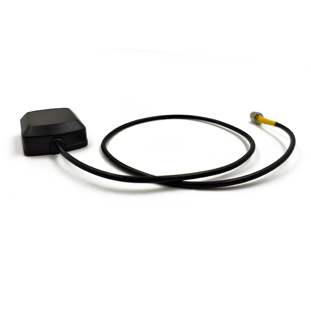
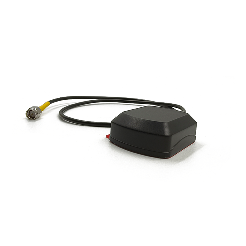
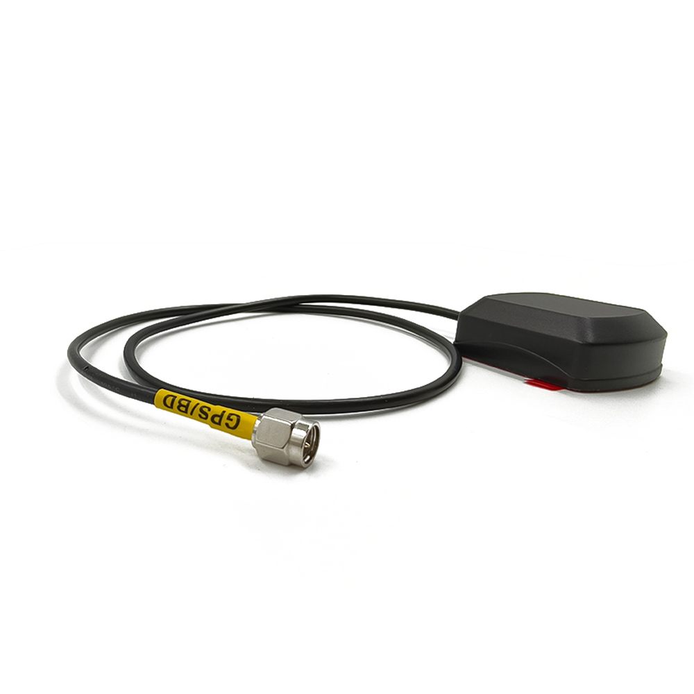
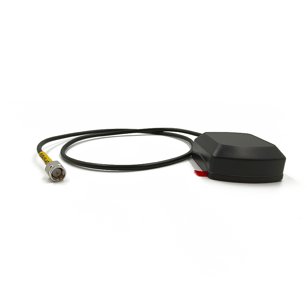
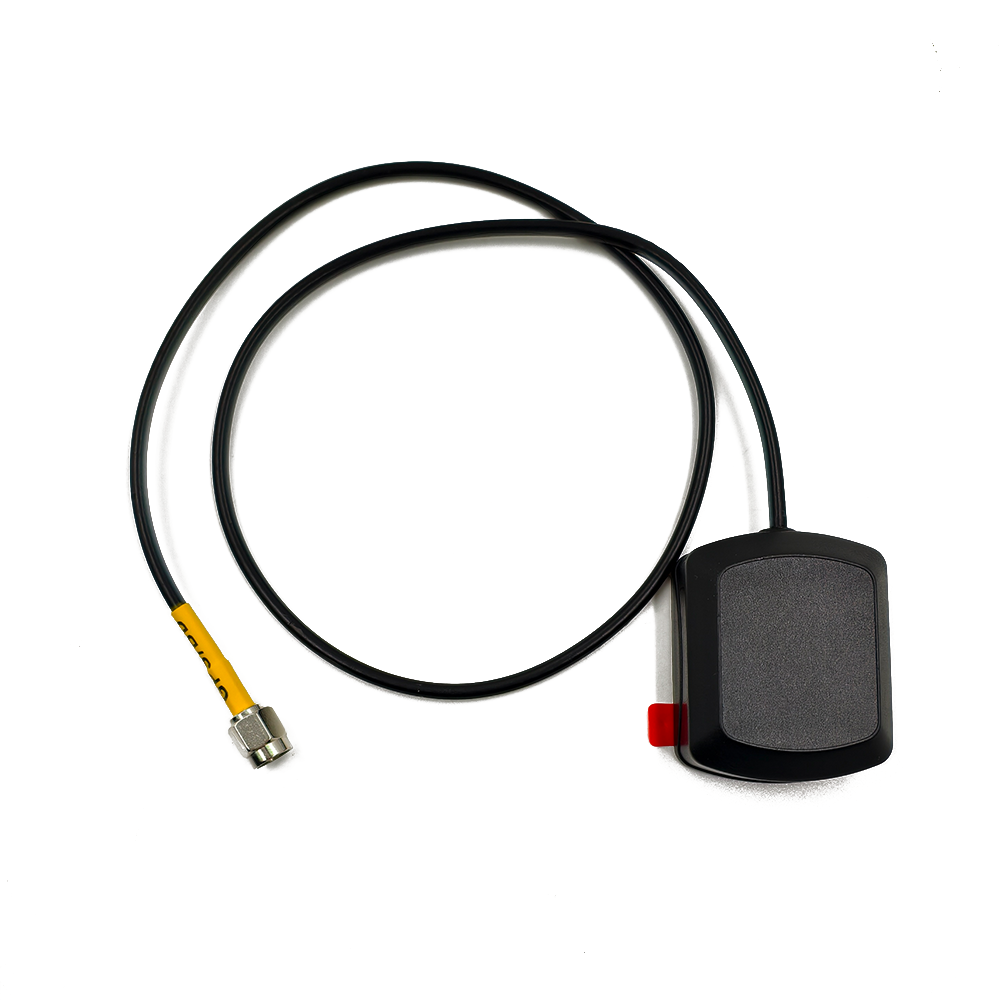
The TOXU KC.GA.00117 is an active external GNSS antenna designed for GPS L1 and BDS B1 positioning equipment. It combines an RHCP patch antenna, integrated low-noise amplifier, compact adhesive-mount housing, 300mm RG174 coaxial cable, and straight SMA male connector.
● GPS L1 and BDS B1 Reception:Supports the 1560–1580MHz frequency range, including GPS L1 at 1575.42MHz and BDS B1 at 1561.098MHz.
● Integrated 28dB LNA Gain:The internal low-noise amplifier provides a typical gain of 28dB with a specified noise figure below 1.5dB.
● 3.3V Active Antenna Design:Operates from a 3.3V antenna bias supply with a specified current consumption below 20mA.
● RHCP Patch Antenna:The internal right-hand circularly polarized patch provides a typical zenith gain of 3.0dBic at GPS L1 and BDS B1 frequencies.
● Compact Adhesive-Mount Housing:The approximately 45.98 × 36.94 × 15.29mm housing uses a 3M self-adhesive base for installation on compatible clean and flat surfaces.
● 300mm RG174 Cable and SMA Male:The standard configuration includes a 300±15mm RG174 coaxial cable and straight SMA male connector with male center pin.
The TOXU KC.GA.00117 is an active external GNSS antenna designed for vehicle positioning, navigation, tracking, telematics, and compatible industrial positioning equipment.
The antenna operates across 1560–1580MHz, covering GPS L1 at 1575.42MHz and BDS B1 at 1561.098MHz. Its internal patch antenna provides right-hand circular polarization for compatible satellite navigation signal reception.
The passive patch antenna has a specified typical zenith gain of 3.0dBic at both 1561.098MHz and 1575.42MHz. An integrated low-noise amplifier provides 28dB typical gain with a noise figure below 1.5dB.
The complete antenna assembly, including the patch antenna, LNA, and cable, has a specified typical overall zenith gain of 29dBic. This overall value should not be confused with the passive patch-antenna gain.
The active circuit operates from a 3.3V antenna bias supply and consumes less than 20mA under the specified conditions. The connected GNSS receiver must therefore support active-antenna bias power through its RF input.
The KC.GA.00117 uses a compact black housing measuring approximately 45.98 × 36.94 × 15.29mm. A 3M double-sided adhesive layer on the bottom supports installation on compatible clean, dry, and flat surfaces.
The standard configuration includes a 300±15mm RG174 coaxial cable and a straight nickel-plated SMA male connector with male center pin.
The KC.GA.00117 is an active GNSS antenna only. It does not contain a GNSS receiver and cannot calculate position independently.
GPS L1 and BDS B1 Signal Support
The 1560–1580MHz operating range covers GPS L1 at 1575.42MHz and BDS B1 at 1561.098MHz.
Active GNSS Antenna Design
The integrated low-noise amplifier strengthens received GNSS signals before transmission through the coaxial cable.
28dB Typical LNA Gain
The internal LNA provides a specified typical gain of 28dB for connection to compatible powered GNSS antenna inputs.
Noise Figure Below 1.5dB
The specified low-noise amplifier noise figure is below 1.5dB under the defined test conditions.
RHCP Patch Antenna
The internal patch uses right-hand circular polarization for compatible GPS L1 and BDS B1 signal reception.
3.0dBic Typical Patch Zenith Gain
The passive patch antenna provides a specified typical zenith gain of 3.0dBic at 1561.098MHz and 1575.42MHz.
3.3V Low-Power Operation
The active antenna operates from a 3.3V bias supply with a specified current consumption below 20mA.
50-Ohm RF Interface
The complete antenna assembly uses a standard 50-ohm output impedance for compatible GNSS receiver inputs.
3M Self-Adhesive Mounting
The adhesive backing enables installation on compatible clean and flat surfaces without requiring a magnetic base or mounting hole.
300mm RG174 Coaxial Cable
The standard finished cable length is 300±15mm for short-distance connection to the GNSS receiver or positioning terminal.
Straight SMA Male Connector
The standard nickel-plated SMA male connector uses a male center pin for connection to a compatible SMA female antenna port.
Compact External Housing
The approximately 45.98 × 36.94 × 15.29mm housing supports integration into vehicle and industrial positioning equipment with limited installation space.
-40°C to +85°C Operating Range
The specified operating and storage temperature ranges support demanding vehicle and industrial environments, subject to final application validation.
OEM Customization Support
Cable length, connector type, housing label, packaging, and RF configuration can be evaluated according to project requirements.
| Model | KC.GA.00117 |
| Product Type | Active External GNSS Antenna |
| Supported GNSS Systems | GPS / BDS |
| Supported Signals | GPS L1 / BDS B1 |
| Frequency Range | 1560–1580MHz |
| Center Frequency | 1570MHz |
| GPS L1 Frequency | 1575.42MHz |
| BDS B1 Frequency | 1561.098MHz |
| 10dB Return-Loss Bandwidth | 20MHz |
| Antenna Type | Active |
| Polarization | RHCP |
| Patch Zenith Gain at 1561.098MHz | 3.0dBic Typical |
| Patch Zenith Gain at 1575.42MHz | 3.0dBic Typical |
| LNA Gain | 28dB Typical |
| Noise Figure | <1.5dB |
| LNA Output VSWR | ≤2.0 |
| Overall Zenith Gain | 29dBic Typical |
| Overall Output VSWR | 2.0 Typical |
| Output Impedance | 50 Ohm |
| Operating Voltage | 3.3V DC |
| Current Consumption | <20mA |
| Housing Dimensions | Approximately 45.98 × 36.94 × 15.29mm |
| Housing Color | Black |
| Mounting Type | 3M Self-Adhesive Mount |
| Cable Type | RG174 Coaxial Cable |
| Finished Cable Length | 300±15mm |
| Standard Connector | Straight SMA Male |
| Connector Center Contact | Male Pin |
| Connector Plating | Nickel Plated |
| Operating Temperature | -40°C to +85°C |
| Operating Humidity | 20% to 95% RH |
| Storage Temperature | -40°C to +85°C |
| Storage Humidity | 20% to 95% RH |
| Recommended Storage Conditions | -20°C to +45°C, Maximum 80% RH |
| Customization | Cable Length / Connector / Label / Packaging / RF Configuration |
The 3.0dBic value refers to the passive patch antenna’s typical zenith gain. The 28dB value refers to the internal LNA gain, while the 29dBic value is the specified typical overall zenith gain measured through the antenna, LNA, and cable.
The available engineering materials do not provide an approved IP protection rating, waterproof test result, salt-spray rating, vibration rating, or UV-resistance specification. These claims should not be added until supported by approved test data.
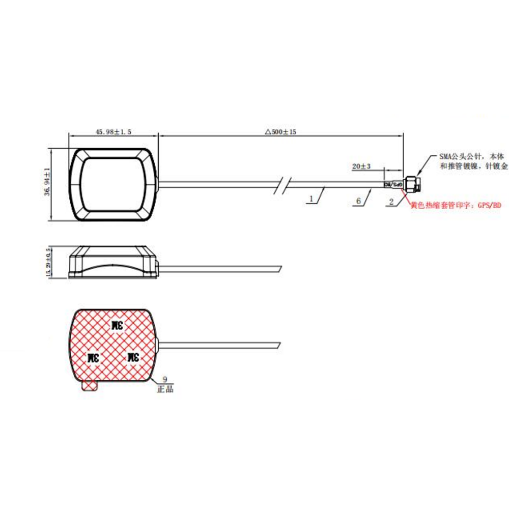
The standard KC.GA.00117 housing measures approximately 45.98±1.5mm in length, 36.94±1.5mm in width, and 15.29±1.5mm in height. The standard finished RG174 cable length is 300±15mm.
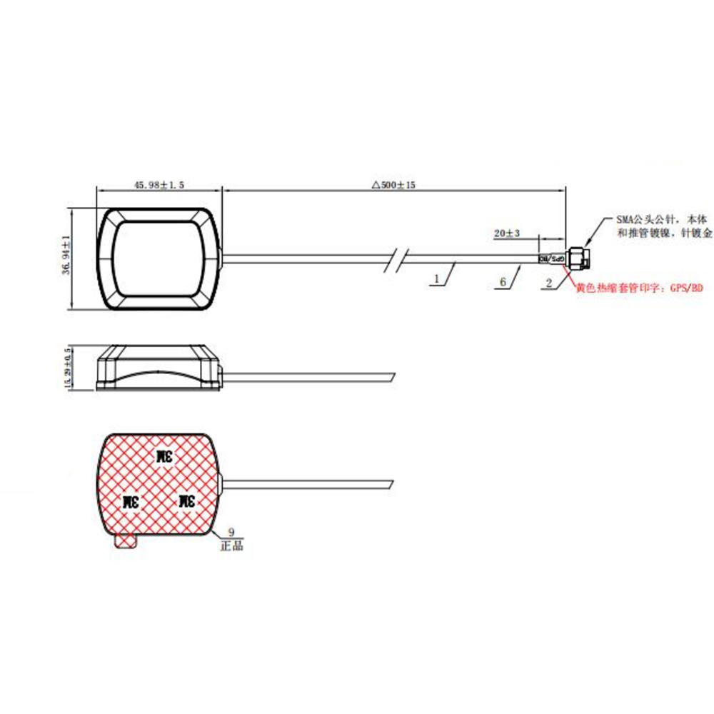
The drawing specifies an approximately 20±3mm heat-shrink section near the SMA connector. Connector structure, cable length, adhesive mounting area, and installation clearance should be confirmed against the approved drawing and sample before volume production.
• Vehicle Tracking Devices
• Vehicle Navigation Systems
• Fleet Management Terminals
• Telematics Control Units
• GPS and BDS Positioning Receivers
• Asset Tracking Equipment
• Automotive Positioning Terminals
• Industrial Positioning Equipment
• Remote-Monitoring Devices
• Construction and Agricultural Machinery
• Embedded Equipment Requiring an External GNSS Antenna
The KC.GA.00117 is an active GNSS antenna containing an integrated low-noise amplifier. It must be connected to a compatible GNSS receiver input capable of supplying 3.3V antenna bias power through the RF cable.
The connected receiver should support a current requirement of less than 20mA and provide suitable active-antenna monitoring and protection according to the complete system design.
The receiver must support GPS L1 at 1575.42MHz and/or BDS B1 at 1561.098MHz. The antenna cannot add GPS or BDS compatibility to a receiver that does not support the corresponding signal.
The standard connector is a straight SMA male with male center pin. It must be connected to a mechanically and electrically compatible SMA female antenna port.
The 3M adhesive base should be installed on a clean, dry, smooth, and compatible surface. Dust, oil, moisture, high surface roughness, curved surfaces, and repeated removal may reduce adhesive strength.
For improved satellite signal reception, install the antenna with a suitable view of the sky and away from high-power transmitters, switching power supplies, metal shielding structures, and other potential interference sources.
The antenna does not contain a GNSS receiver and cannot calculate position independently. Positioning performance depends on the connected receiver, firmware, satellite visibility, antenna placement, electromagnetic environment, and complete system design.
This product supports the GPS L1 and BDS B1 frequency region only. It should not be described as a multi-frequency L1/L2/L5 RTK antenna. RTK capability depends on the connected receiver, supported signals, correction data, firmware, and complete positioning system.
Final RF performance, connector compatibility, positioning performance, and adhesive reliability should be verified on the customer’s finished equipment before volume production.
TOXU provides GNSS antenna design, active antenna integration, RF tuning, cable processing, connector assembly, prototype verification, testing, and volume-production support for vehicle equipment manufacturers and system integrators.
Our product range includes GPS and GNSS antennas, multi-frequency RTK antennas, automotive combination antennas, cellular antennas, WiFi and Bluetooth antennas, RF cable assemblies, RF connectors, PCBA manufacturing, GNSS modules, receiver boards, and integrated positioning solutions.
With IATF16949 and ISO9001-certified manufacturing capabilities, TOXU supports customized cable lengths, connector configurations, antenna housings, labels, packaging, RF testing, quality control, and stable delivery for overseas B2B projects.
Q: Which GNSS signals does the KC.GA.00117 support?
A: Its 1560–1580MHz frequency range covers GPS L1 at 1575.42MHz and BDS B1 at 1561.098MHz.
Q: Is the KC.GA.00117 an active antenna?
A: Yes. It contains an integrated low-noise amplifier and requires bias power from a compatible GNSS receiver.
Q: What voltage does the antenna require?
A: The specified operating voltage is 3.3V DC, with current consumption below 20mA.
Q: What is the difference between the 3.0dBic, 28dB, and 29dBic values?
A: The 3.0dBic value is the passive patch antenna’s typical zenith gain, 28dB is the internal LNA gain, and 29dBic is the specified typical overall gain measured through the antenna, LNA, and cable.
Q: What is the antenna polarization?
A: The formal electrical specification defines the patch antenna polarization as RHCP.
Q: What cable does the standard antenna use?
A: It uses RG174 coaxial cable with a finished length of 300±15mm.
Q: What connector does it use?
A: The standard configuration uses a straight nickel-plated SMA male connector with male center pin.
Q: How is the antenna installed?
A: It uses a 3M double-sided adhesive layer for installation on a clean, dry, flat, and compatible surface.
Q: Is this a magnetic-mount antenna?
A: No. The standard KC.GA.00117 uses adhesive mounting and does not contain a magnetic base.
Q: What are the housing dimensions?
A: The finished-product drawing specifies approximately 45.98±1.5 × 36.94±1.5 × 15.29±1.5mm.
Q: Does the KC.GA.00117 support RTK?
A: It covers GPS L1 and BDS B1 only and is not a multi-frequency L1/L2/L5 RTK antenna. The antenna itself cannot calculate an RTK position.
Q: Is the KC.GA.00117 waterproof?
A: The available specification does not provide an approved IP protection rating. Waterproof or IP claims should only be made after confirmation through an approved environmental test report.
Q: Can the cable and connector be customized?
A: Yes. Cable length, cable type, connector series, label, packaging, and RF configuration can be evaluated according to project requirements.
Lucy Yang | lucy.y@toxutech.com
Nicole Li | nicole@toxutech.com
Dotty Zhao | sales04@toxutech.com
Global Business Director / Sales Team / Global Operations


 En
En Cn
Cn Korean
 Home >

