

-
Products -PCBA Manufacturing RF Connectors RF Cable Assemblys Embedded Antennas External Antennas GNSS Positioning Solutions
RF Connectors

RF Cable Assemblys
Embedded Antennas
External Antennas
GNSS Positioning Solutions



 Language


Language

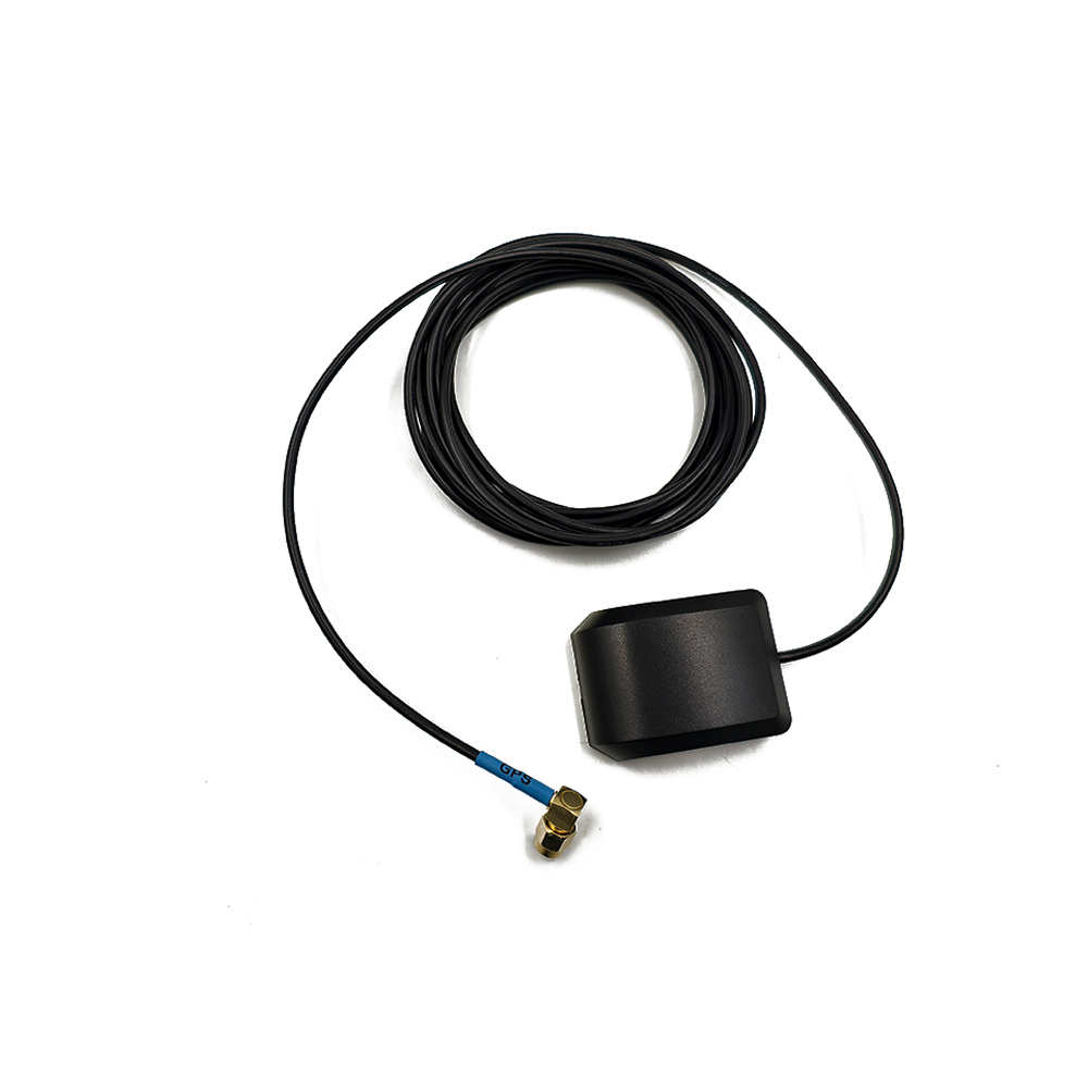
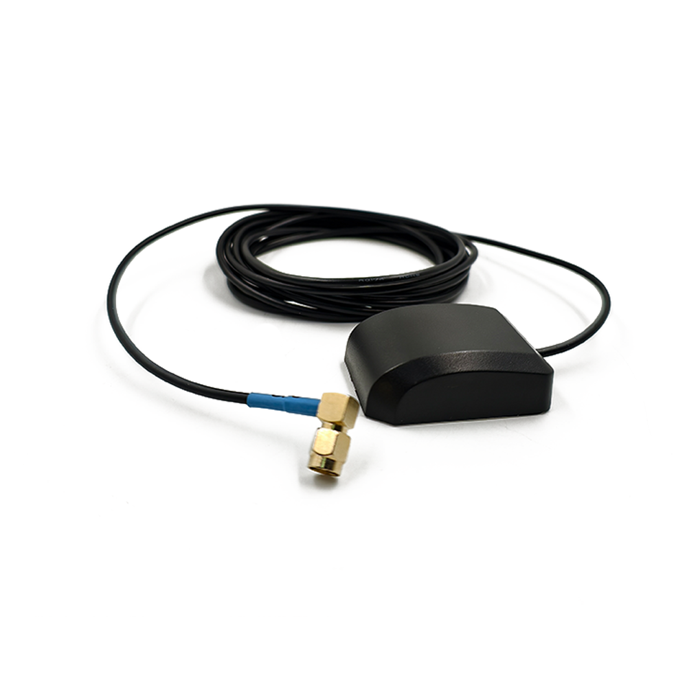
Model: KC.GA.00102
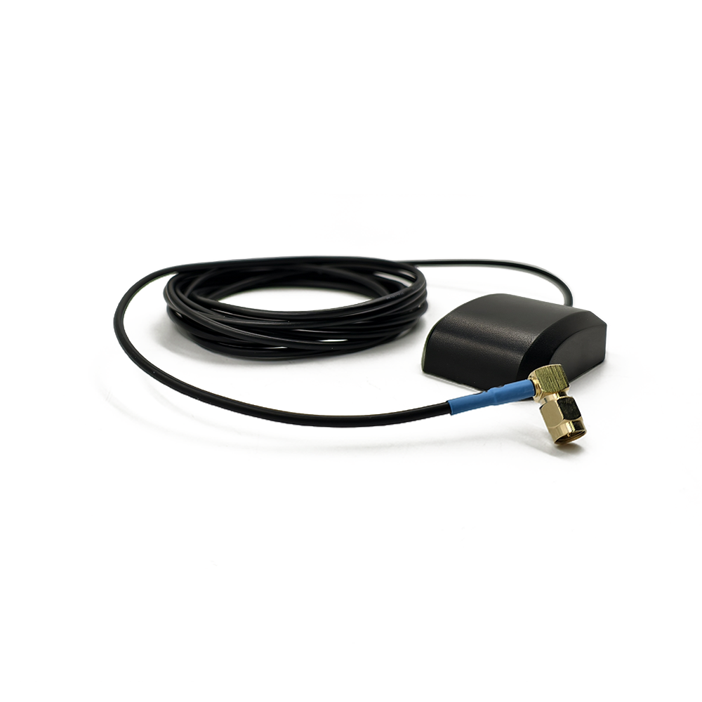
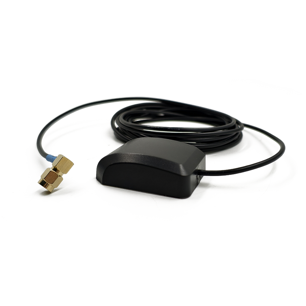
The TOXU KC.GA.00102 is an active external GNSS antenna designed for GPS L1 and BDS B1 positioning equipment. It combines a compact mouse-style housing, integrated LNA, 3M adhesive mounting base, 3m RG174 coaxial cable, and right-angle SMA male connector.
● GPS L1 and BDS B1 Reception:Supports GPS L1 at 1575.42MHz and BDS B1 at 1561MHz for compatible positioning, navigation, and tracking receivers.
● Integrated 28dB Active Gain:The internal low-noise amplifier provides a specified active gain of 28dB for compatible powered GNSS antenna inputs.
● RHCP Ceramic Antenna Element:Uses a 25 × 25 × 4mm right-hand circularly polarized ceramic antenna element for GPS and BDS signal reception.
● 3M Adhesive Mounting:The self-adhesive base enables installation on compatible clean and flat surfaces without drilling a mounting hole.
● 3m RG174 Coaxial Cable:The standard 3000±30mm RG174 cable provides flexible routing between the antenna and the connected GNSS receiver.
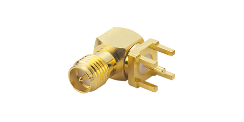
● Right-Angle SMA Male Connector:The 90° SMA male connector supports installation where straight connector clearance is limited.
The TOXU KC.GA.00102 is an active external GNSS antenna designed for compatible positioning, navigation, tracking, telematics, and industrial terminal equipment.
The antenna supports GPS L1 at 1575.42MHz and BDS B1 at 1561MHz. It uses a 25 × 25 × 4mm ceramic antenna element with right-hand circular polarization and an internal low-noise amplifier for active GNSS signal reception.
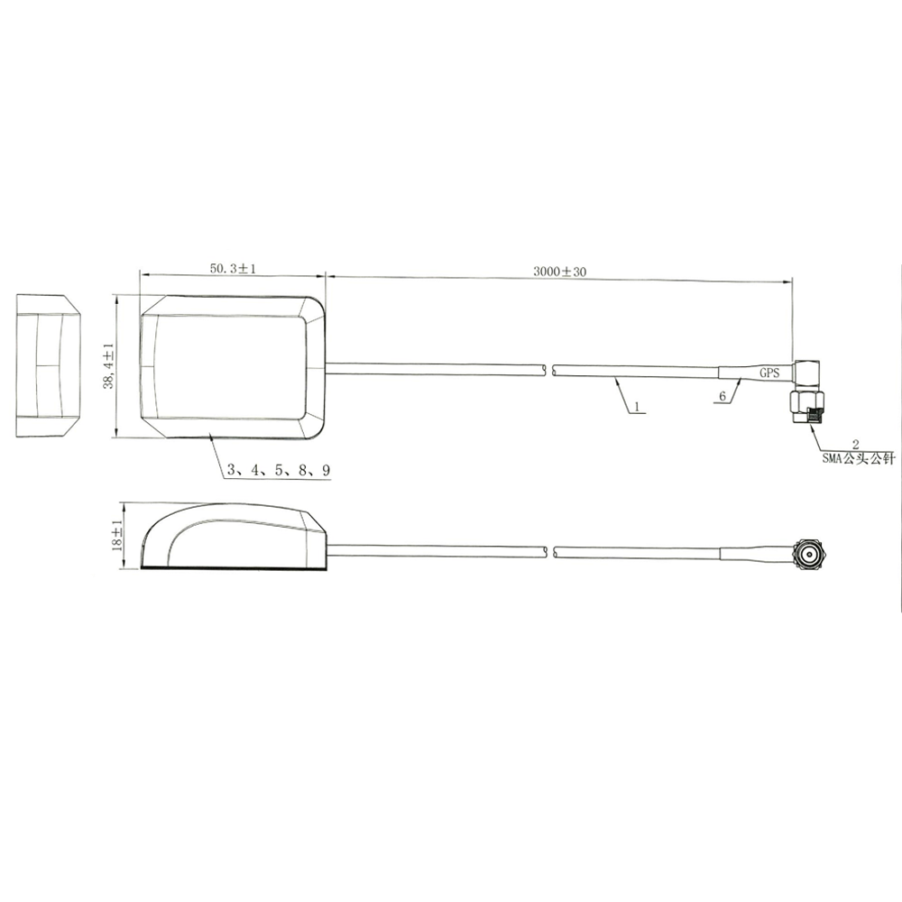
The available engineering drawing specifies a gain value of 28. Because this product contains an integrated LNA, the value is presented on this page as 28dB active gain rather than 28dBi passive antenna-element gain.
The KC.GA.00102 uses a compact mouse-style black housing measuring approximately 50.3 × 38.4 × 18mm. A 3M double-sided adhesive layer on the bottom supports installation on compatible clean and flat surfaces.
The standard configuration includes a 3000±30mm RG174 coaxial cable and a 90° right-angle SMA male connector with male center pin. The right-angle connector structure is suitable for installations with limited rear clearance around the receiver antenna port.
This product is an active GNSS antenna. It requires bias power from a compatible GNSS receiver through the RF cable and does not calculate position independently.
GPS L1 and BDS B1 Signal Support
Supports GPS L1 at 1575.42MHz and BDS B1 at 1561MHz for compatible satellite navigation receivers.
Active GNSS Antenna Design
The integrated LNA strengthens received GNSS signals before transmission through the 3m coaxial cable.
28dB Specified Active Gain
The available engineering drawing specifies a 28dB active gain for use with compatible powered GNSS antenna inputs.
RHCP Ceramic Antenna Element
The internal 25 × 25 × 4mm ceramic antenna element uses right-hand circular polarization for compatible GPS and BDS signal reception.
VSWR of ≤2.0
The specified VSWR is ≤2.0 at the supported GNSS frequencies under the defined test conditions.
3M Self-Adhesive Installation
The integrated adhesive layer supports installation on clean, dry, smooth, and compatible surfaces without using a magnetic base.
3m RG174 Coaxial Cable
The standard finished cable length is 3000±30mm, providing flexible routing within vehicles, equipment cabinets, and positioning terminals.
Right-Angle SMA Male Connector
The 90° SMA male connector with male center pin provides a threaded RF connection while reducing the installation space required behind the receiver port.
Compact Mouse-Style Housing
The approximately 50.3 × 38.4 × 18mm housing is suitable for equipment requiring a compact external GNSS antenna.
-20°C to +60°C Operating Range
The specified operating temperature range supports compatible vehicle, tracking, navigation, and industrial applications, subject to final system validation.
OEM Configuration Support
Cable length, cable type, connector configuration, housing label, packaging, and antenna tuning can be evaluated according to project requirements.
| Model | KC.GA.00102 |
| Product Type | Active External GNSS Antenna |
| Supported GNSS Systems | GPS / BDS |
| Supported Signals | GPS L1 / BDS B1 |
| Frequency | 1575.42MHz / 1561MHz |
| Antenna Type | Active |
| Integrated LNA | Yes |
| LNA Component | ATR2660S, according to the available BOM |
| Active Gain | 28dB |
| VSWR | ≤2.0 |
| Input Impedance | 50 Ohm |
| Polarization | RHCP |
| Ceramic Antenna Element | 25 × 25 × 4mm |
| PCB Dimensions | 28 × 28 × 0.7mm |
| Housing Type | Mouse-Style External Housing |
| Housing Dimensions | Approximately 50.3 × 38.4 × 18mm |
| Housing Color | Black |
| Mounting Type | 3M Self-Adhesive Mount |
| Adhesive Thickness | 0.5mm |
| Cable Type | RG174 Coaxial Cable |
| Finished Cable Length | 3000±30mm |
| Standard Connector | 90° Right-Angle SMA Male |
| Connector Center Contact | Male Pin |
| Connector Plating | Gold Plated |
| Operating Temperature | -20°C to +60°C |
| Storage Temperature | -20°C to +60°C |
| Environmental Compliance | RoHS Compliant |
| Standard Packaging | 1 Piece per Bag |
| Customization | Cable Length / Cable Type / Connector / Label / Packaging / RF Configuration |
The available drawing describes the gain value as 28dBi. Because the KC.GA.00102 contains an integrated LNA, this value is presented as 28dB active gain and must not be interpreted as 28dBi passive ceramic antenna gain.
The available engineering materials do not specify the LNA operating voltage, operating current, noise figure, out-of-band rejection, or IP protection rating. These parameters should not be added until supported by an approved specification or test report.
The standard KC.GA.00102 housing measures approximately 50.3±1mm in length, 38.4±1mm in width, and 18±1mm in height. The standard finished RG174 cable length is 3000±30mm.
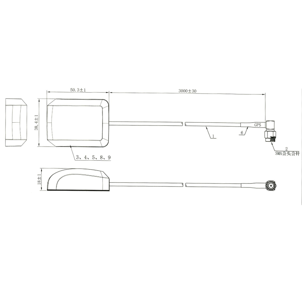
The separate production cable drawing specifies a raw cutting length of 3030±20mm. This is a manufacturing dimension and is not the finished cable length shown to customers.
Housing dimensions, connector orientation, mating interface, cable length, adhesive mounting area, and installation clearance should be confirmed against the approved drawing and sample before volume production.
• Vehicle Tracking Devices
• Fleet Management Terminals
• Vehicle Navigation Equipment
• GPS and BDS Positioning Receivers
• Telematics Control Units
• Asset Tracking Equipment
• Industrial Positioning Terminals
• Remote-Monitoring Devices
• Construction and Agricultural Machinery
• Navigation and Timing Equipment
• Embedded Equipment Requiring an External GNSS Antenna
The KC.GA.00102 is an active antenna containing an integrated LNA. It should be connected to a GNSS receiver input capable of supplying the required antenna bias power through the RF cable.
The available engineering materials do not specify the required operating voltage or current. These electrical parameters must be confirmed before connecting the antenna to a GNSS module, receiver board, telematics terminal, or customer-designed PCBA.
The connected receiver must support GPS L1 at 1575.42MHz and/or BDS B1 at 1561MHz. The antenna cannot add satellite-system compatibility to a receiver that does not support the corresponding signal.
The standard connector is a 90° SMA male with male center pin. It must be connected to a mechanically and electrically compatible SMA female antenna port.
The right-angle connector can reduce the space required behind the receiver, but cable routing should avoid excessive bending, pulling, twisting, and repeated mechanical stress close to the connector.
The 3M adhesive surface should be installed on a clean, dry, smooth, and compatible substrate. Dust, oil, moisture, rough surfaces, curved mounting areas, and repeated removal may reduce adhesive strength.
For improved GNSS signal reception, the antenna should be installed with a suitable view of the sky and away from high-power transmitters, switching power supplies, metal shielding structures, and other potential interference sources.
The 3m RG174 cable provides flexible installation but also introduces RF transmission loss. The integrated LNA helps compensate for cable loss, while final performance still depends on the receiver, antenna bias supply, connector condition, cable routing, and installation environment.
This product supports GPS L1 and BDS B1 only. It should not be described as a multi-frequency L1/L2/L5 RTK antenna. RTK capability depends on the connected receiver, supported signals, correction data, firmware, and complete positioning system.
Final RF performance, positioning performance, connector compatibility, and adhesive reliability should be verified on the customer’s finished equipment before volume production.
TOXU provides GNSS antenna design, active antenna integration, RF tuning, cable processing, connector assembly, prototype verification, testing, and volume-production support for equipment manufacturers and system integrators.
Our product range includes GPS and GNSS antennas, multi-frequency RTK antennas, automotive combination antennas, cellular antennas, WiFi and Bluetooth antennas, RF cable assemblies, RF connectors, PCBA manufacturing, GNSS modules, receiver boards, and integrated positioning solutions.
With IATF16949 and ISO9001-certified manufacturing capabilities, TOXU supports customized cable lengths, connector types, antenna housings, labels, packaging, RF testing, quality control, and stable delivery for overseas B2B projects.
Q: Which GNSS signals does the KC.GA.00102 support?
A: It supports GPS L1 at 1575.42MHz and BDS B1 at 1561MHz.
Q: Is the KC.GA.00102 an active antenna?
A: Yes. It contains an integrated LNA and requires bias power from a compatible GNSS receiver.
Q: What is the specified gain?
A: The available drawing specifies 28dB active gain. It must not be interpreted as 28dBi passive ceramic antenna gain.
Q: What is the antenna polarization?
A: The available product drawing specifies right-hand circular polarization.
Q: What cable does the standard antenna use?
A: It uses RG174 coaxial cable with a finished length of 3000±30mm.
Q: Why does the production cable drawing show 3030±20mm?
A: The 3030±20mm value is the raw cable cutting length used during production. The finished antenna cable length is 3000±30mm.
Q: What connector does the KC.GA.00102 use?
A: The standard configuration uses a 90° right-angle SMA male connector with male center pin.
Q: How is the antenna installed?
A: It uses a 3M double-sided adhesive layer for installation on a clean, dry, smooth, and compatible surface.
Q: Is this a magnetic-mount antenna?
A: No. The standard KC.GA.00102 uses adhesive mounting and does not contain a magnetic base.
Q: What are the housing dimensions?
A: The finished-product drawing specifies approximately 50.3±1 × 38.4±1 × 18±1mm.
Q: Does the KC.GA.00102 support RTK?
A: It supports GPS L1 and BDS B1 only. It is not a multi-frequency L1/L2/L5 RTK antenna, and the antenna itself cannot calculate an RTK position.
Q: What operating voltage does the antenna require?
A: The available engineering materials do not specify the operating voltage or current. These parameters must be confirmed before system integration.
Q: Is the KC.GA.00102 waterproof?
A: The available materials do not provide an IP protection rating. Waterproof or IP claims should only be made after confirmation through an approved specification or environmental test report.
Q: Can the cable and connector be customized?
A: Yes. Cable type, cable length, connector series, connector orientation, label, packaging, and RF configuration can be evaluated according to project requirements.
Lucy Yang | lucy.y@toxutech.com
Nicole Li | nicole@toxutech.com
Dotty Zhao | sales04@toxutech.com
Global Business Director / Sales Team / Global Operations


 En
En Cn
Cn Korean
 Home >

