

-
Products -PCBA Manufacturing RF Connectors RF Cable Assemblys Embedded Antennas External Antennas GNSS Positioning Solutions
RF Connectors

RF Cable Assemblys
Embedded Antennas
External Antennas
GNSS Positioning Solutions


 Language


Language

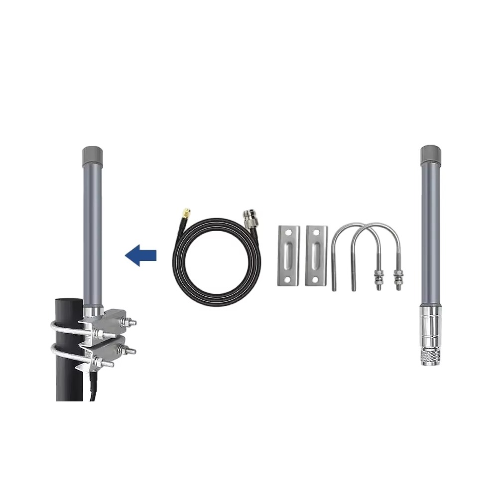
Model: TX-A70
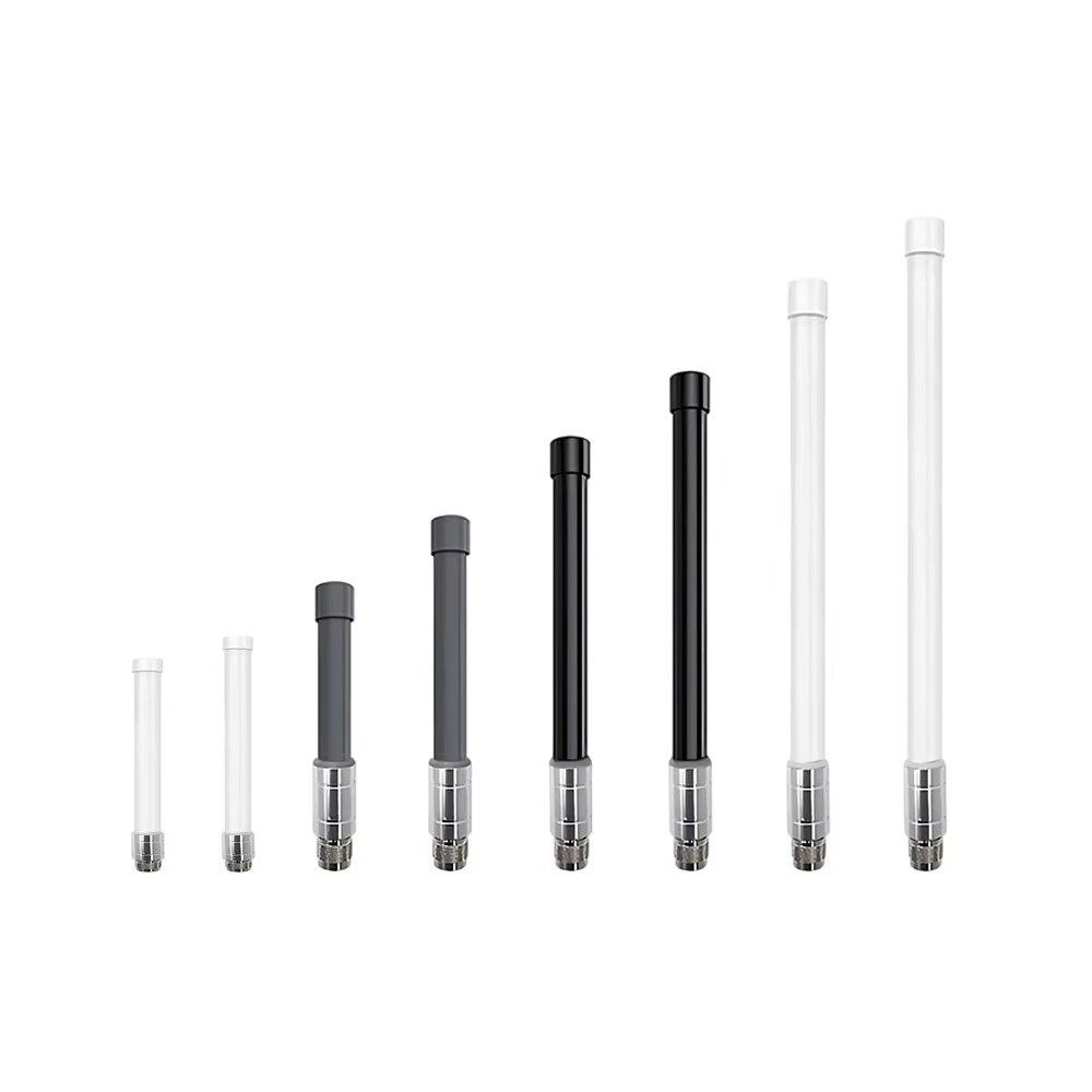
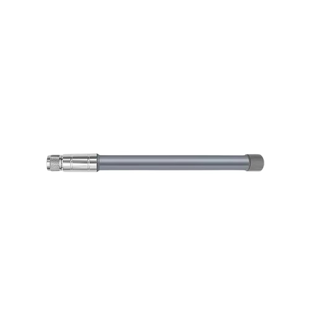
The TOXU TX-A70 is an outdoor omnidirectional fiberglass antenna designed for compatible 700-850MHz wireless communication equipment. It features vertical polarization, 50Ω impedance, a copper-tube internal radiator, and an N-type connector for pole-mounted or wall-mounted installations.
● 700-850MHz Configuration: Designed for compatible wireless communication systems operating within the specified frequency range.
● Omnidirectional Coverage: Provides 360-degree horizontal signal coverage for fixed outdoor communication equipment.
● Fiberglass Radome: The external fiberglass structure is suitable for pole-mounted and wall-mounted outdoor installations.
● Configurable Gain and Length: Available gain and antenna-length options should be selected according to the required frequency and project configuration.
● N-Type Connector: Supplied with an N-type connector in the standard configuration, with alternative connector options available for evaluation.
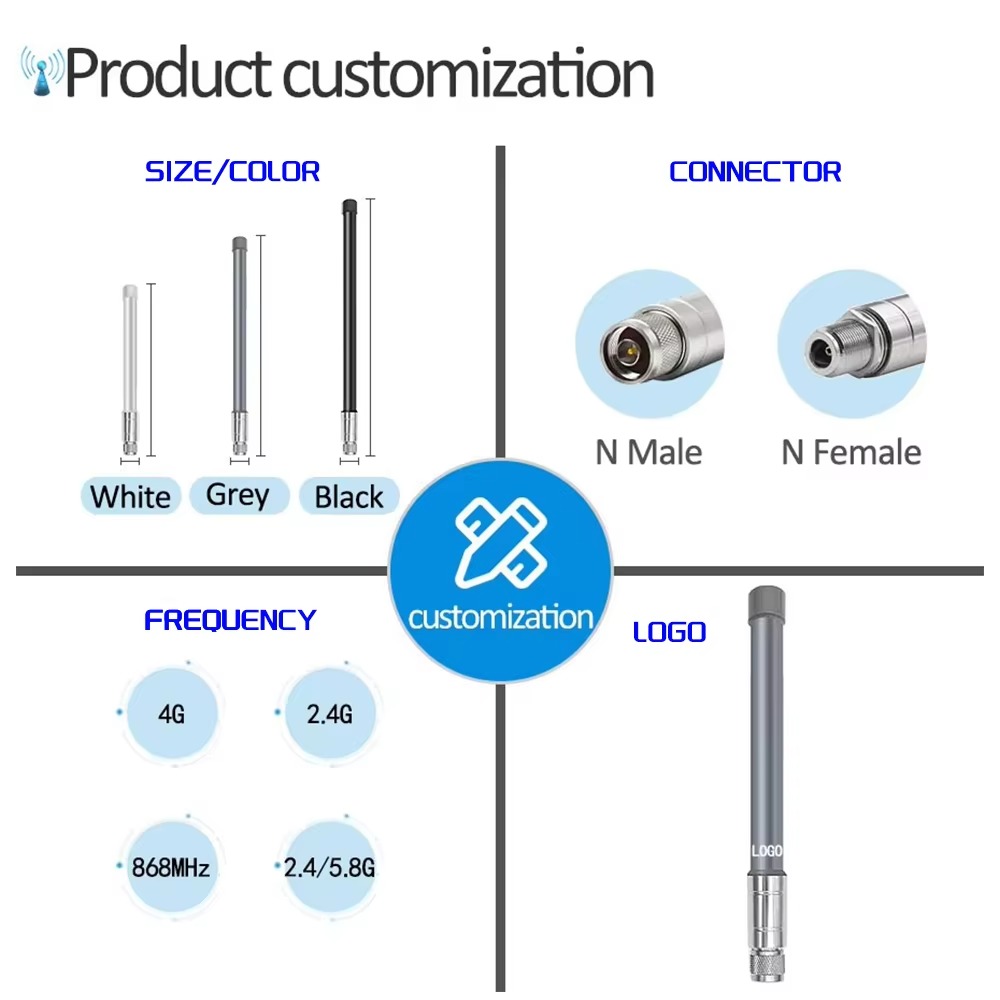
● OEM and ODM Support: TOXU supports frequency tuning, gain configuration, antenna length, connector selection, mounting accessories, and volume production.
The TOXU TX-A70 is an outdoor omnidirectional fiberglass antenna designed for compatible wireless communication equipment operating within the 700-850MHz frequency range.
The antenna uses vertical polarization and a 50Ω impedance configuration. Its omnidirectional radiation structure provides 360-degree horizontal coverage, making it suitable for fixed wireless terminals, telemetry equipment, industrial communication systems, gateways, repeaters, base-station equipment, and other compatible outdoor RF applications.
The TX-A70 uses a fiberglass external radome and a copper-tube internal radiator. It can be installed on a pole or wall using suitable mounting hardware and connected to the equipment through an N-type RF connector.
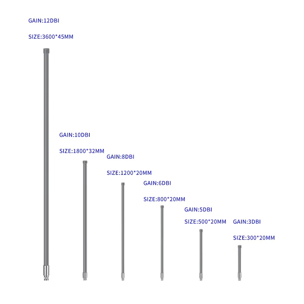
Available configurations include different gain levels and antenna lengths. These values are not interchangeable: the final antenna gain, length, internal structure, and RF performance depend on the selected operating frequency and approved project specification.
TOXU can evaluate alternative frequency ranges, gain configurations, antenna lengths, connectors, colors, mounting accessories, and packaging according to the customer’s equipment and project requirements.
700-850MHz Operating Range
The current TX-A70 configuration is designed for compatible wireless communication equipment operating within the 700-850MHz frequency range.
Omnidirectional Signal Coverage
The antenna provides 360-degree horizontal radiation coverage, reducing the need to point the antenna toward a specific communication direction.
Vertical Polarization
The vertically polarized configuration is suitable for compatible fixed wireless, telemetry, industrial communication, and outdoor RF systems.
Fiberglass Outdoor Structure
The fiberglass radome provides a practical external structure for pole-mounted and wall-mounted communication equipment.
Copper-Tube Internal Radiator
The internal antenna structure uses a copper-tube radiating element according to the listed product configuration.
Configurable Gain and Antenna Length
Gain options from 2dBi to 7dBi and antenna lengths of 25cm, 30cm, 60cm, or 100cm can be evaluated. The final combination must be confirmed according to the operating frequency and approved antenna design.
N-Type RF Connection
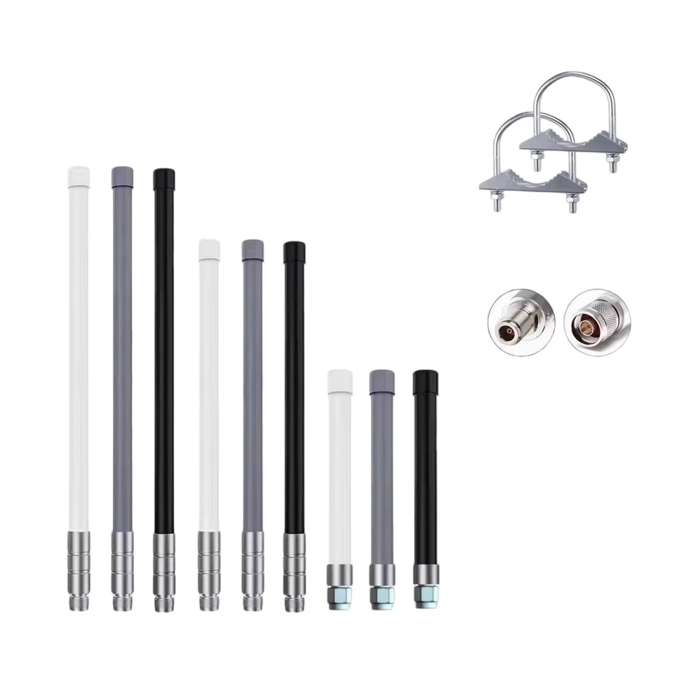
The standard configuration uses an N-type connector. The exact connector gender and interface must be confirmed before ordering.
Flexible Installation
The antenna supports compatible pole-mounting or wall-mounting arrangements according to the installation structure and selected mounting accessories.
OEM and ODM Configuration
TOXU can evaluate frequency tuning, gain, antenna length, connector type, radome color, mounting hardware, branding, and packaging for suitable projects.
| Model | TX-A70 |
| Product Type | Outdoor Omnidirectional Fiberglass Antenna |
| Frequency Range | 700-850MHz |
| Alternative Frequencies | Available for Custom Evaluation |
| Gain Options | 2 / 3 / 4 / 5 / 6 / 7dBi, Subject to Selected Configuration |
| VSWR | ≤2.0 |
| Input Impedance | 50Ω |
| Polarization | Vertical |
| Radiation Pattern | Omnidirectional in the Horizontal Plane |
| Antenna Length Options | 25 / 30 / 60 / 100cm, Subject to Selected Configuration |
| Inner Radiator Material | Copper Tube |
| Connector Type | N Type or Customized |
| Mounting Method | Pole Mount or Wall Mount |
| Operating Temperature | -40°C to +80°C |
| Storage Temperature | -40°C to +85°C |
| Environmental Compliance | RoHS-Compliant Materials |
| Customization | Frequency, Gain, Length, Connector, Color, Mounting Hardware, Branding and Packaging |
The available gain and antenna-length values represent configurable options rather than the performance of one universal antenna. The final frequency, gain, antenna length, connector, and mechanical structure must be confirmed in the approved specification before production.
700-850MHz Wireless Communication Systems
Industrial Wireless Gateways
Telemetry and Remote-Monitoring Equipment
Wireless Data-Transmission Systems
Fixed Outdoor Communication Terminals
Compatible Base-Station Equipment
Repeaters and Signal-Distribution Equipment
Industrial Control and Monitoring Systems
Private Wireless Networks
Outdoor IoT Communication Equipment
Application suitability depends on the equipment frequency, transmitter power, receiver sensitivity, RF connector, feeder cable, antenna mounting height, surrounding structures, and local regulatory requirements.
The TX-A70 should be installed vertically to maintain its specified vertical polarization and omnidirectional horizontal radiation pattern.
Before ordering, customers should provide the exact operating frequency or required bandwidth. General descriptions such as “700MHz antenna” are not sufficient for final matching when the equipment operates over a narrower or different frequency range.
The selected RF cable should have a 50Ω impedance and compatible connectors. Cable attenuation increases with cable length and operating frequency, so a suitable low-loss coaxial cable should be selected according to the installation distance.
The antenna should be installed as high and clear of surrounding obstructions as practical. Nearby metal structures, walls, roofs, electrical equipment, and other antennas can affect impedance matching and radiation performance.
The mounting bracket, connector sealing, grounding arrangement, lightning protection, and feeder-cable routing should be evaluated according to the outdoor installation environment.
Actual communication range cannot be determined by antenna gain alone. It also depends on transmitter power, receiver sensitivity, cable loss, mounting height, terrain, obstructions, interference, and the complete RF system design.
Frequency Tuning
TOXU can evaluate the antenna structure according to the required center frequency, bandwidth, wireless module, RF equipment, and operating environment.
Gain and Length Configuration
Different gain and antenna-length options can be evaluated according to the required frequency and radiation characteristics. Higher gain generally requires a longer antenna structure and produces a narrower vertical radiation pattern.
Connector Configuration
The standard product uses an N-type connector. Connector gender and alternative RF interfaces can be evaluated according to the customer’s feeder cable and equipment connection.
Mounting Accessories
Pole-mounting or wall-mounting hardware can be evaluated according to the antenna size, installation position, pole diameter, and project requirements.
Prototype and RF Verification
TOXU supports prototype development, network-analyzer testing, RF verification, sample approval, and configuration confirmation before volume production.
Volume-Production Support
After sample approval, TOXU supports antenna assembly, RF inspection, quality control, customized labeling, packaging, and stable volume delivery.
TOXU provides antenna design, RF tuning, connector integration, prototype verification, testing, and volume-production support for industrial, IoT, telemetry, cellular, GNSS, automotive-related, and wireless communication equipment manufacturers.
Our engineering team can evaluate antenna performance according to the customer’s operating frequency, required bandwidth, equipment structure, installation position, RF cable, connector, mounting environment, and complete wireless system.
In addition to fiberglass omnidirectional antennas, TOXU provides cellular antennas, GNSS antennas, embedded antennas, combination antennas, RF cable assemblies, RF connectors, PCBA manufacturing, GNSS modules, receiver boards, and integrated hardware solutions.
With IATF16949 and ISO9001-certified manufacturing capabilities, TOXU supports engineering verification, customized production, quality control, and stable delivery for overseas B2B projects.
Q: Does one TX-A70 antenna cover all the frequency bands shown on the old product page?
A: No. The current listed configuration covers 700-850MHz. Other frequency versions require separate antenna tuning and specification confirmation.
Q: Which gain and antenna length should I select?
A: The suitable gain and length depend on the required frequency, installation environment, coverage pattern, mounting height, and complete RF system. Please provide your exact operating frequency before selection.
Q: Is higher antenna gain always better?
A: No. Higher gain normally produces a narrower vertical radiation pattern and may require a longer antenna. The correct configuration should be selected according to the required coverage area.
Q: Which connector does the TX-A70 use?
A: The standard configuration uses an N-type connector. The exact connector gender must be confirmed according to the connected RF cable or equipment interface.
Q: Can the frequency and antenna length be customized?
A: Yes. TOXU can evaluate frequency tuning, gain, antenna length, connector, radome color, mounting accessories, branding, and packaging according to the project requirements.
Q: Can TOXU guarantee a specific communication distance?
A: Communication distance cannot be guaranteed from antenna specifications alone. It depends on transmitter power, receiver sensitivity, cable loss, antenna height, terrain, obstacles, interference, and the complete RF system.
Lucy Yang | lucy.y@toxutech.com
Nicole Li | nicole@toxutech.com
Dotty Zhao | sales04@toxutech.com
Global Business Director / Sales Team / Global Operations


 En
En Cn
Cn Korean
 Home >

