

-
Products -PCBA Manufacturing RF Connectors RF Cable Assemblys Embedded Antennas External Antennas GNSS Positioning Solutions
RF Connectors

RF Cable Assemblys
Embedded Antennas
External Antennas
GNSS Positioning Solutions





 Language


Language

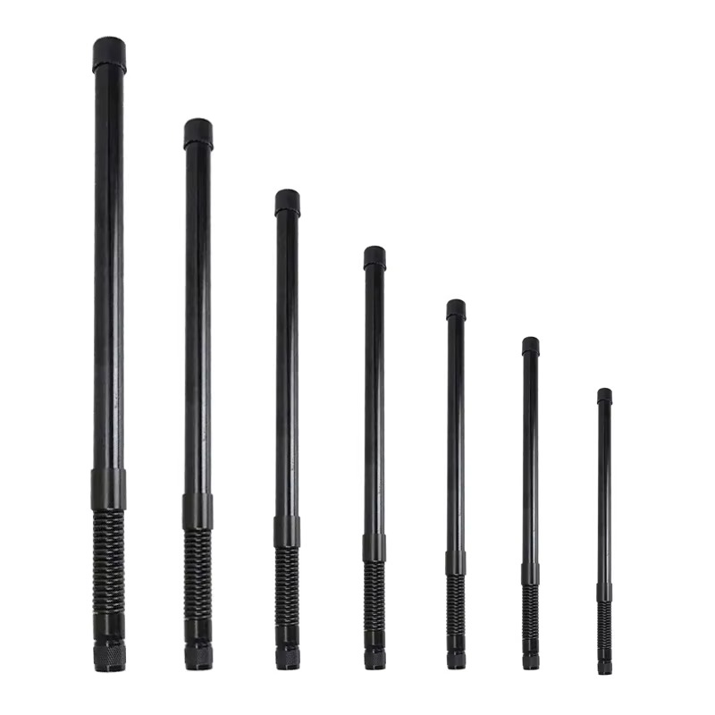
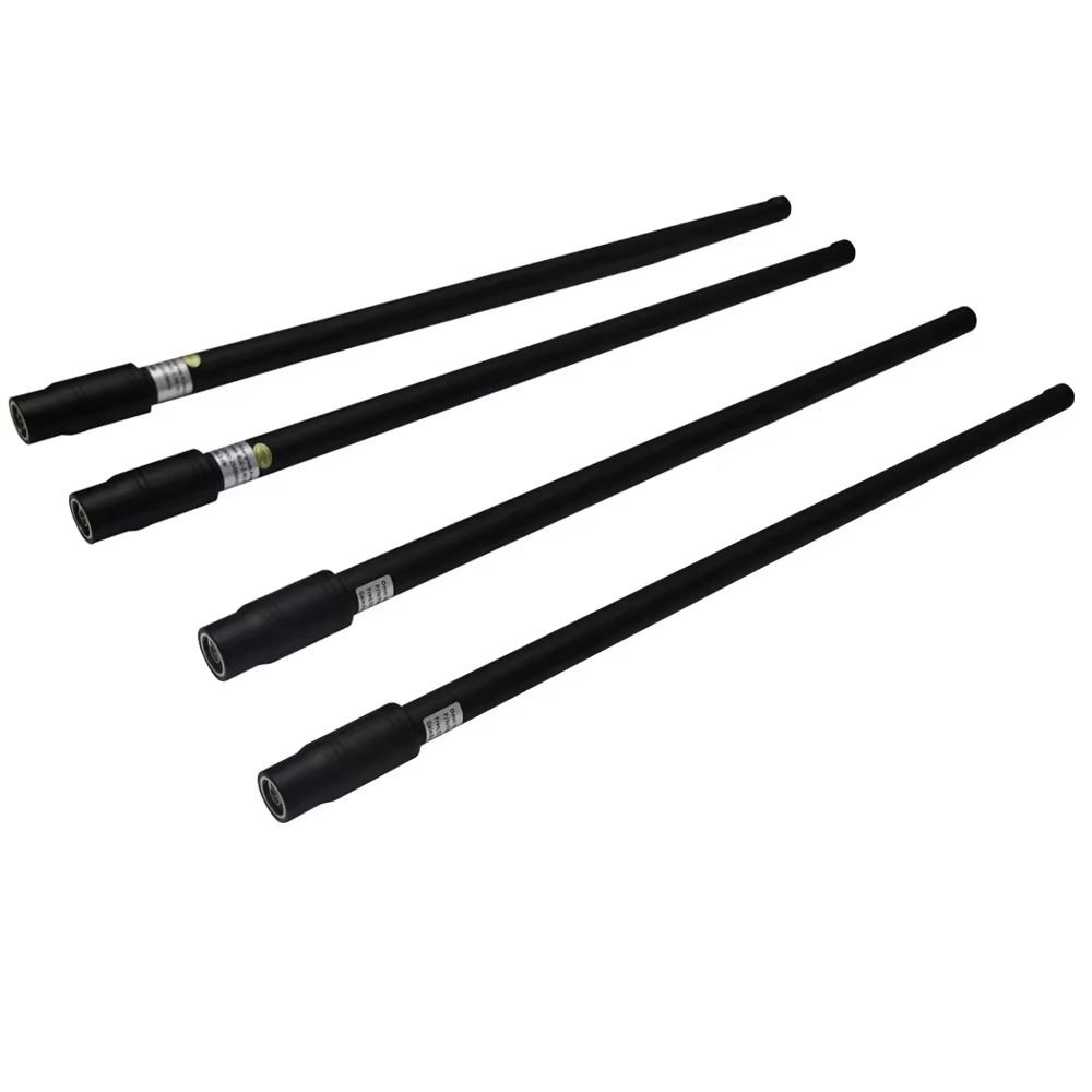
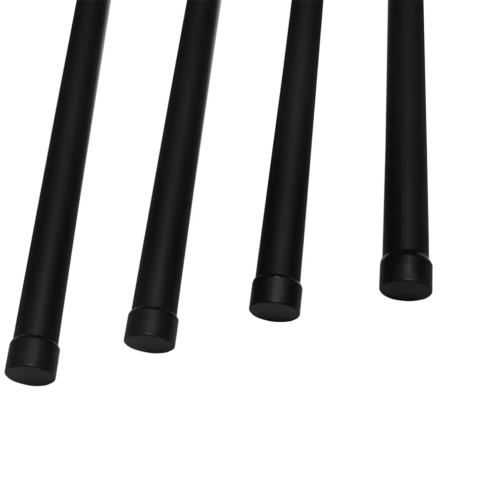
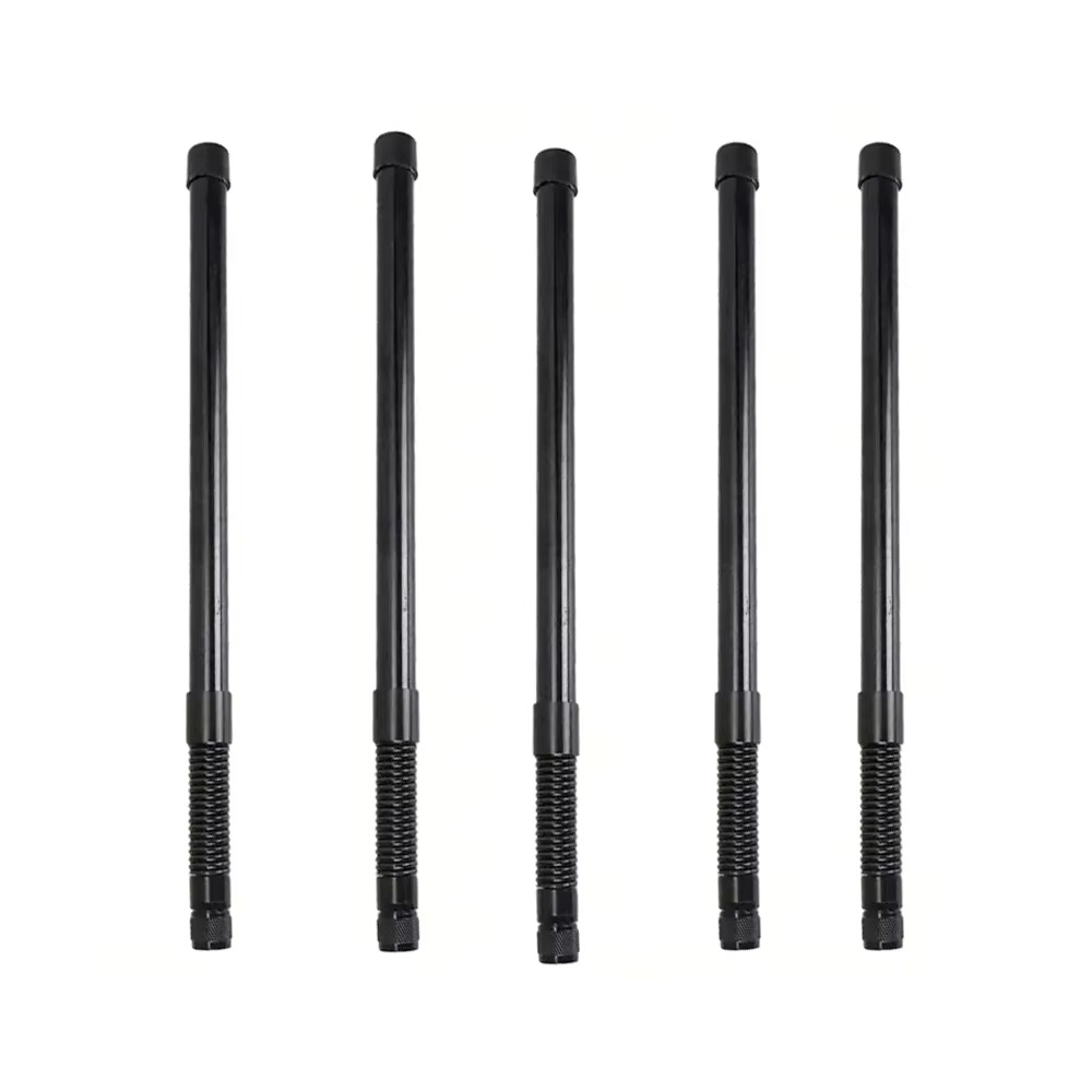
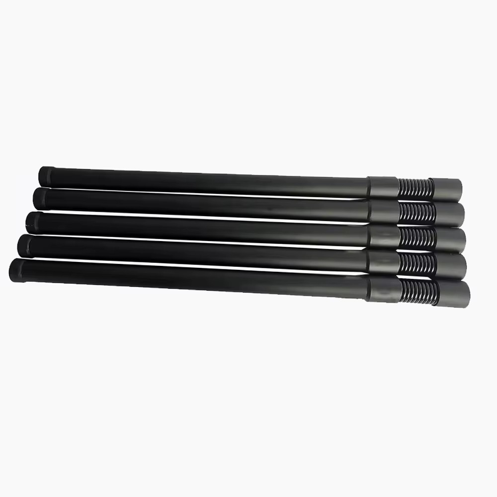
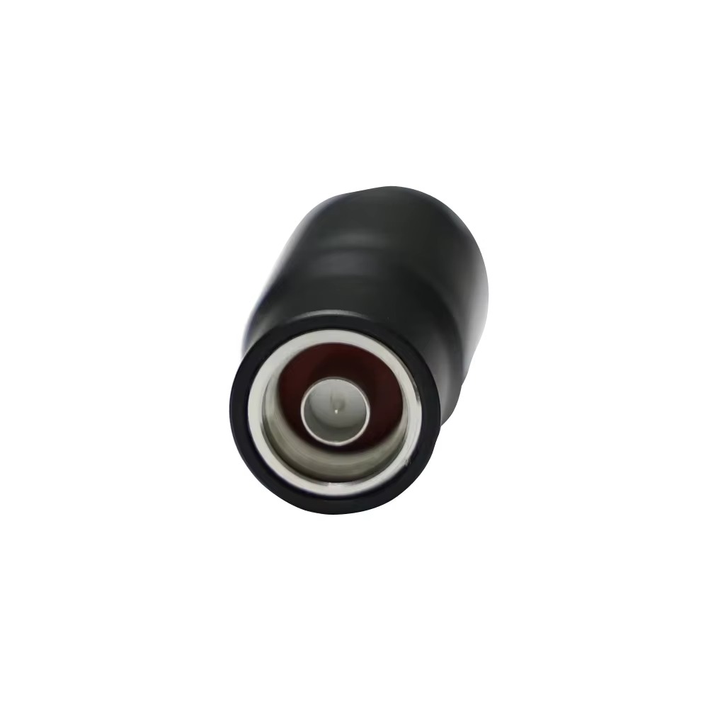
Model: TX-A65
The TOXU TX-A65 is a customizable outdoor fiberglass omnidirectional antenna series developed for wireless communication, telemetry, remote monitoring, industrial control, RF monitoring, and specialized radio equipment. Different frequency, gain, antenna-length, connector, cable, and mounting configurations are available according to project requirements.
● Multiple Frequency Options: Available in separately tuned 433MHz, 900MHz, 1.2GHz, 1.5GHz, 2.4GHz, 5.2GHz, and 5.8GHz versions.
● Individually Tuned Design: Each antenna is designed and tuned for the selected operating frequency; the listed frequencies are not simultaneously covered by one standard antenna.
● 5–10dBi Gain Options: Available gain depends on the selected frequency, bandwidth, antenna length, and mechanical configuration.
● Outdoor Fiberglass Housing: The fiberglass radome helps protect the internal antenna structure and supports outdoor pole-mounted installation.
● Flexible RF Configuration: Antenna frequency, length, connector, coaxial cable, and mounting accessories can be configured for compatible equipment.
● OEM and ODM Support: TOXU provides antenna design, RF tuning, prototype verification, connector integration, and volume-production support.
The TOXU TX-A65 is a customizable outdoor fiberglass omnidirectional antenna series designed for wireless communication, telemetry, remote monitoring, industrial control, RF monitoring, radio transmission, and other specialized RF equipment.
This page represents a series of separately configured antennas rather than one fixed wideband antenna. Available frequency options include 433MHz, 900MHz, 1.2GHz, 1.5GHz, 2.4GHz, 5.2GHz, and 5.8GHz.
Each TX-A65 version is individually designed and tuned according to the selected operating frequency, required bandwidth, target gain, antenna length, connector, cable, and installation environment.
The listed frequencies are available configuration options and are not simultaneously covered by one standard antenna. Customers should confirm the required frequency version before ordering.
The TX-A65 uses a fiberglass radome and a vertically polarized omnidirectional design suitable for compatible outdoor pole-mounted wireless equipment.
Frequency, gain, antenna length, connector type, coaxial cable, cable length, mounting bracket, and mechanical configuration can be customized for OEM and ODM projects.
| Frequency Option | Configuration |
| 433MHz | Separately designed and tuned version |
| 900MHz | Separately designed and tuned version |
| 1.2GHz | Separately designed and tuned version |
| 1.5GHz | Separately designed and tuned version |
| 2.4GHz | Separately designed and tuned version |
| 5.2GHz | Separately designed and tuned version |
| 5.8GHz | Separately designed and tuned version |
Important: The frequencies above represent separately available antenna versions. They must not be interpreted as the simultaneous operating range of one standard TX-A65 antenna.
Final frequency range, bandwidth, gain, antenna length, connector, cable configuration, and mechanical dimensions must be confirmed according to the selected version.
Multiple Customized Frequency Versions
Available in separately tuned 433MHz, 900MHz, 1.2GHz, 1.5GHz, 2.4GHz, 5.2GHz, and 5.8GHz configurations for different wireless systems.
Individually Tuned RF Performance
Each antenna is tuned according to the selected frequency, required bandwidth, equipment interface, antenna gain, and installation environment.
5–10dBi Gain Options
Different gain configurations are available depending on the selected frequency, antenna length, bandwidth, and mechanical structure. Final gain must be confirmed for each version.
Omnidirectional Radiation Pattern
The vertically polarized omnidirectional design supports signal transmission and reception around the antenna when installed vertically in a suitable operating environment.
Outdoor Fiberglass Radome
The fiberglass housing helps protect the internal antenna structure and supports compatible outdoor pole-mounted equipment installations.
50Ω RF Interface
The antenna uses a standard 50Ω RF design for integration with compatible radio equipment, transceivers, gateways, telemetry devices, and RF systems.
DC-Grounded Configuration
The listed series supports a DC-grounded antenna configuration. Complete lightning, surge, and grounding protection must still be evaluated at the system level.
Flexible Connector and Cable Options
N male, N female, coaxial cable, cable length, and other RF connection configurations can be selected according to the customer’s equipment interface.
Customized Mechanical Structure
Antenna length, radome dimensions, mounting bracket, applicable pole diameter, cable outlet, and connector configuration can be customized according to project requirements.
| Model | TX-A65 |
| Product Type | Custom Outdoor Fiberglass Omnidirectional Antenna Series |
| Frequency Options | 433MHz / 900MHz / 1.2GHz / 1.5GHz / 2.4GHz / 5.2GHz / 5.8GHz |
| Frequency Configuration | Each antenna version is individually designed and tuned |
| Gain Options | 5–10dBi, depending on frequency and antenna configuration |
| VSWR | ≤1.5 |
| Input Impedance | 50Ω |
| Polarization | Vertical |
| Radiation Pattern | Omnidirectional |
| Maximum Input Power | 100W |
| Lightning Protection | DC Grounding |
| Connector Options | N Male / N Female or Customized |
| Cable Length | 38cm or Customized |
| Antenna Length | Customized according to frequency and gain requirements |
| Mounting Method | Outdoor Pole Mount with L-Bracket |
| Applicable Pole Diameter | 25–40mm |
| Wind Resistance | 60m/s |
| Operating Temperature | -40°C to +85°C |
| Customization | Frequency, Bandwidth, Gain, Length, Connector, Cable, and Mounting Structure |
The specifications above describe the available series-level configurations. Final electrical and mechanical specifications must be confirmed for the selected TX-A65 frequency version before ordering.
Industrial Wireless Communication Systems
Telemetry and Data Transmission Equipment
Remote-Monitoring Systems
Wireless Sensor Networks
ISM-Band Communication Equipment
LPWAN and IoT Gateways
Radio Communication Equipment
Industrial Remote-Control Systems
RF Monitoring and Detection Equipment
Counter-UAV System RF Equipment
Security and Surveillance Systems
Specialized Sub-GHz and Microwave Communication Systems
For RF monitoring, detection, or counter-UAV equipment, the TX-A65 serves only as an external RF antenna. Detection, signal processing, transmission, and other system functions are provided by the connected equipment rather than the antenna itself.
The TX-A65 can be integrated with compatible radios, transceivers, gateways, telemetry units, RF monitoring equipment, remote-control systems, industrial wireless terminals, and other 50Ω RF devices.
Customers must select an antenna version that matches the exact operating frequency and bandwidth of the connected equipment. For example, a TX-A65 tuned for 433MHz cannot automatically be used with 900MHz, 1.2GHz, 1.5GHz, 2.4GHz, 5.2GHz, or 5.8GHz equipment.
The antenna should normally be installed vertically on a suitable outdoor pole or mounting bracket. Adequate clearance should be maintained from large metal obstructions, high-current circuits, power cables, and strong electromagnetic interference sources.
Actual system performance depends on the selected frequency, antenna gain, installation height, coaxial cable loss, connector configuration, equipment RF matching, surrounding structures, terrain, and operating environment.
The DC-grounded antenna structure can form part of an equipment protection design, but it does not replace complete system-level lightning and surge protection. Appropriate grounding and surge-protection devices should be evaluated for outdoor installations.
Before ordering, customers should provide the exact operating frequency, required bandwidth, target gain, radio or module model, connector type, cable requirement, installation location, pole diameter, mechanical restrictions, and expected order quantity.
1. Requirement Confirmation
The customer provides the target frequency, required bandwidth, gain requirement, equipment model, connector type, cable requirement, antenna dimensions, installation method, and application environment.
2. Antenna Configuration
TOXU evaluates the appropriate antenna length, internal RF structure, fiberglass housing, connector, coaxial cable, and mounting configuration.
3. Prototype Development and Testing
Prototype samples can be developed and tested according to the confirmed electrical and mechanical requirements.
4. Customer Verification
Customers verify the antenna with their actual radio, equipment enclosure, cable routing, mounting structure, and installation environment.
5. Mass-Production Support
After sample approval, TOXU supports production planning, quality inspection, antenna assembly, RF testing, and stable volume delivery.
TOXU provides antenna design, RF tuning, connector integration, prototype development, testing, and mass-production support for wireless communication and industrial equipment manufacturers.
Our engineering team can customize the antenna frequency, bandwidth, gain, internal RF structure, fiberglass housing, antenna length, coaxial cable, RF connector, and mounting method according to the customer’s equipment and application.
TOXU also provides RF cable assemblies, RF connectors, PCBA manufacturing, GNSS modules, receiver boards, and product assembly services, supporting customers from individual RF components to complete hardware integration.
With IATF16949 and ISO9001-certified manufacturing capabilities, TOXU supports engineering verification, quality control, and stable volume production for industrial, IoT, communication, automotive-related, and specialized RF projects.
Q: Does one TX-A65 antenna simultaneously cover all the listed frequencies?
A: No. The listed frequencies represent separately available TX-A65 versions. Each antenna is individually designed and tuned for the selected operating frequency.
Q: Which frequency versions are available?
A: Available options include 433MHz, 900MHz, 1.2GHz, 1.5GHz, 2.4GHz, 5.2GHz, and 5.8GHz. Other frequencies can be evaluated according to project requirements.
Q: Is the antenna gain always 5–10dBi?
A: No. Available gain depends on the selected frequency, required bandwidth, antenna length, and mechanical configuration. Final gain must be confirmed for each version.
Q: Is the TX-A65 a MIMO antenna?
A: The standard TX-A65 is a single-port omnidirectional antenna. A MIMO system normally requires multiple antennas and corresponding RF ports according to the system design.
Q: Is this antenna itself a drone detector or signal jammer?
A: No. The TX-A65 is a passive RF antenna. Detection, monitoring, signal processing, transmission, and other system functions are provided by the connected equipment.
Q: Can the antenna length be customized?
A: Yes. The antenna length can be selected according to the operating frequency, required gain, bandwidth, housing, and installation requirements.
Q: Which connector options are available?
A: N male and N female configurations are available. Other connector and coaxial cable configurations can be evaluated according to the customer’s equipment.
Q: Is the TX-A65 suitable for outdoor installation?
A: The fiberglass housing and pole-mounting structure are intended for compatible outdoor applications. Final environmental, grounding, and lightning-protection requirements should be evaluated according to the complete installation system.
Q: What information is required before ordering?
A: Please provide the exact operating frequency, required bandwidth, target gain, radio or module model, connector type, cable length, installation method, mechanical restrictions, operating environment, and expected order quantity.
Lucy Yang | lucy.y@toxutech.com
Nicole Li | nicole@toxutech.com
Dotty Zhao | sales04@toxutech.com
Global Business Director / Sales Team / Global Operations


 En
En Cn
Cn Korean
 Home >

