

-
Products -PCBA Manufacturing RF Connectors RF Cable Assemblys Embedded Antennas External Antennas Positioning Chips and Modules
RF Connectors

RF Cable Assemblys
Embedded Antennas
External Antennas
Positioning Chips and Modules


 Language


Language


In the modern automotive industry, the integration of advanced positioning and navigation systems has become a standard feature, transforming the driving experience from basic transportation to a connected, efficient, and safe journey. At the core of these navigation systems lies the Global Positioning System (GPS) antenna, a critical component responsible for receiving satellite signals and converting them into actionable location data. Among the various types of GPS antennas available for automotive applications, the waterproof ceramic patch GPS antenna has emerged as a preferred choice due to its unique combination of compact design, high performance, and resilience to harsh environmental conditions. This overview aims to provide a detailed understanding of this antenna type, its role in automotive navigation, and the key factors that make it indispensable in today’s vehicles.
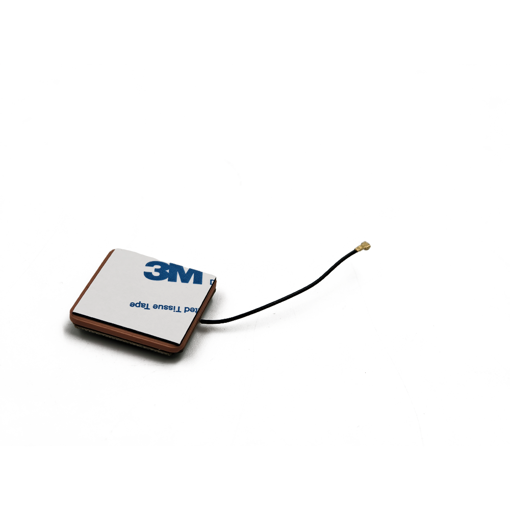
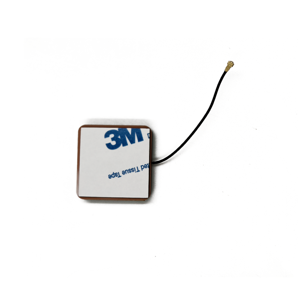
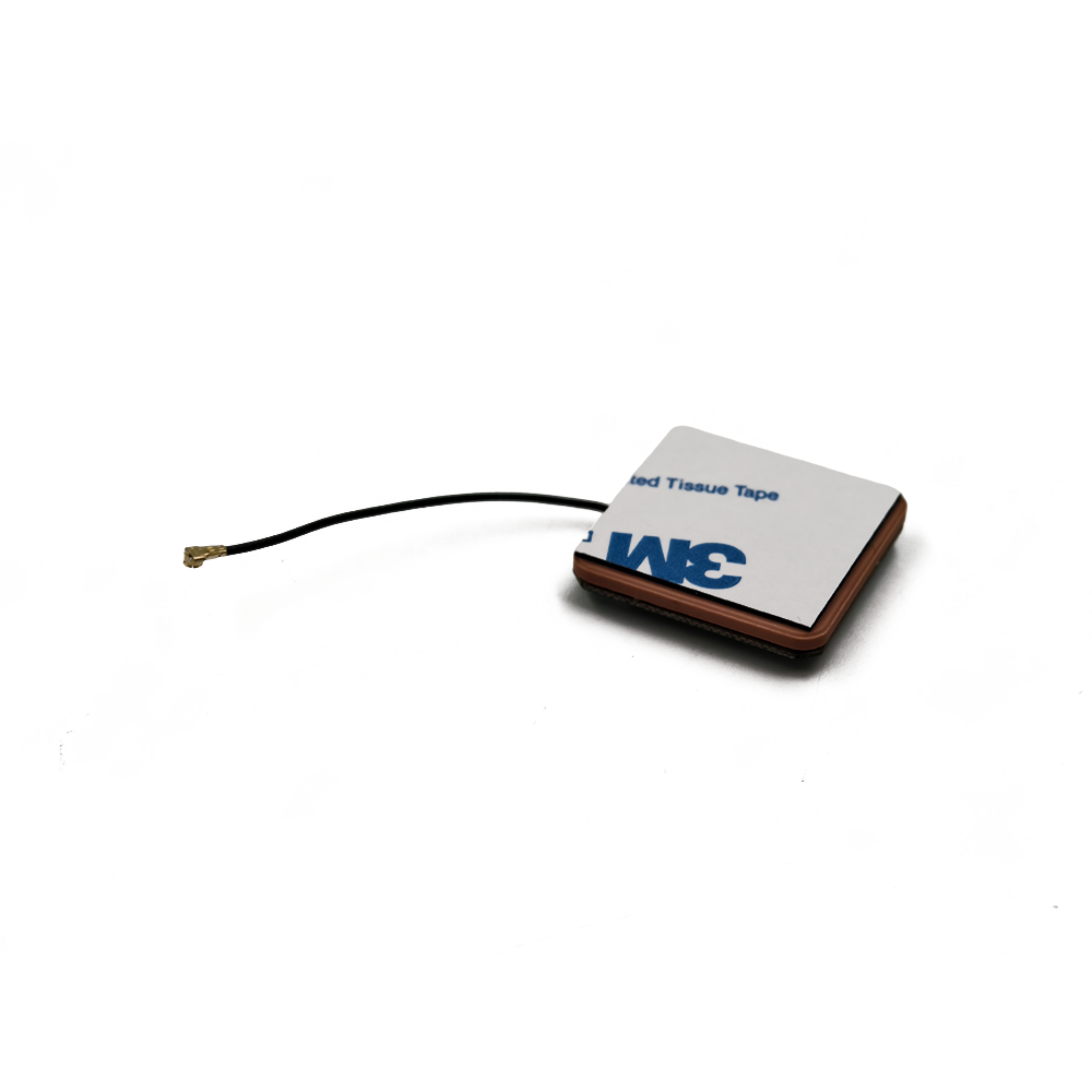
First, it is essential to define the fundamental characteristics of a ceramic patch GPS antenna. Unlike traditional whip antennas or helical antennas, which often feature protruding structures, the patch antenna is a flat, low-profile device that relies on a ceramic substrate as its core component. The ceramic material—typically a high-dielectric-constant (high-εr) material such as barium titanate (BaTiO₃) or alumina (Al₂O₃)—serves two critical purposes: it miniaturizes the antenna size (since higher dielectric constants allow for smaller radiating elements) and enhances signal reception efficiency by focusing electromagnetic energy. The “patch” refers to a thin metallic layer (usually copper) deposited on one side of the ceramic substrate, which acts as the radiating element. The other side of the substrate is coated with a ground plane, a metallic layer that reflects signals back to the patch, improving directivity and reducing interference.
The “waterproof” attribute of this antenna is not an afterthought but a necessity for automotive use. Vehicles operate in a wide range of environmental conditions, from heavy rain, snow, and fog to high humidity, road salt, and even occasional submersion (in the case of off-road vehicles or accidental water exposure). A non-waterproof GPS antenna would quickly degrade in such conditions: water ingress could short-circuit the internal electronics, corrode the metallic components, or disrupt signal propagation, leading to inaccurate positioning or complete navigation failure. To address this, waterproof ceramic patch GPS antennas are designed with robust sealing technologies—such as rubber gaskets, epoxy potting, or IP (Ingress Protection) rated enclosures (typically IP67 or IP68, indicating protection against dust and prolonged water immersion). These features ensure the antenna maintains its performance even in the most challenging weather or driving scenarios.
The role of the waterproof ceramic patch GPS antenna in automotive systems extends far beyond basic navigation. In modern vehicles, GPS data is integrated with other advanced driver assistance systems (ADAS), such as adaptive cruise control (ACC), lane-keeping assist (LKA), and automatic emergency braking (AEB). For example, ACC uses GPS to adjust the vehicle’s speed based on the posted speed limits, while LKA relies on location data to align the vehicle within lane boundaries on highways. Additionally, GPS antennas are critical for telematics systems, which enable features like vehicle tracking (for fleet management or stolen vehicle recovery), remote diagnostics, and real-time traffic updates. In electric vehicles (EVs), GPS data even supports range estimation by accounting for elevation changes and route terrain. Without a reliable, waterproof GPS antenna, these essential features would be compromised, undermining both driver convenience and safety.
Another key aspect of the waterproof ceramic patch GPS antenna is its compatibility with the evolving landscape of satellite navigation systems. While GPS (developed by the United States) is the most widely used system, modern antennas often support multi-constellation reception, including GLONASS (Russia), Galileo (European Union), and BeiDou (China). This multi-constellation capability improves signal availability, especially in urban canyons (where tall buildings block GPS signals) or dense foliage, by tapping into a larger number of satellites. The ceramic patch design is well-suited for multi-constellation support because its flat profile allows for the integration of multiple radiating elements (each tuned to a different constellation’s frequency) within a small footprint, making it easy to install in various parts of the vehicle (e.g., on the roof, behind the windshield, or in the rear spoiler).
To understand the significance of the waterproof ceramic patch GPS antenna, it is helpful to compare it to other automotive GPS antenna types. Whip antennas, for instance, are inexpensive but have a large, protruding design that is prone to damage (e.g., from low-hanging branches or car washes) and poor waterproofing. Helical antennas offer good signal gain but are bulkier than patch antennas, making them less suitable for modern vehicles with sleek designs. Dielectric resonator antennas (DRAs) are another alternative, but they tend to be more expensive and have lower efficiency than ceramic patch antennas. In contrast, the waterproof ceramic patch antenna balances size, performance, cost, and durability—making it the ideal choice for most passenger cars, trucks, SUVs, and commercial vehicles.
In summary, the waterproof ceramic patch GPS antenna is a vital component of modern automotive navigation and connectivity systems. Its low-profile ceramic design enables compact installation, while its waterproof features ensure reliability in harsh environments. By supporting multi-constellation reception and integrating with ADAS and telematics, it plays a central role in enhancing driver safety, convenience, and the overall connected car experience. As vehicles become more autonomous and connected, the demand for high-performance, durable GPS antennas will only grow, solidifying the position of the waterproof ceramic patch antenna as a cornerstone of automotive technology.
The design and construction of a waterproof ceramic patch GPS antenna for cars are meticulous processes that balance electrical performance, mechanical durability, and environmental resilience. Every component—from the ceramic substrate to the sealing materials—is carefully selected and engineered to ensure the antenna meets the strict requirements of automotive applications, including high signal reception, resistance to water and corrosion, and compatibility with vehicle design constraints. This section provides a detailed breakdown of the key design considerations, component selection, and manufacturing processes that define this antenna type.
2.1 Core Design Principles
The design of a ceramic patch GPS antenna is guided by two primary goals: optimizing electromagnetic performance (i.e., signal gain, directivity, and bandwidth) and ensuring mechanical robustness (i.e., waterproofing, shock resistance, and thermal stability). To achieve these goals, designers must address several critical parameters:
2.1.1 Dielectric Constant of the Ceramic Substrate
The ceramic substrate is the heart of the patch antenna, and its dielectric constant (εr) is the most influential factor in determining the antenna’s size and performance. GPS signals operate in the L-band, with the primary frequency for GPS L1 being 1575.42 MHz. The size of the patch (radiating element) is inversely proportional to the square root of the dielectric constant—higher εr values allow for smaller patch sizes, which is crucial for fitting the antenna into compact automotive spaces (e.g., behind the windshield or in the roof module).
Common ceramic materials used include:
Alumina (Al₂O₃): εr ≈ 9.8, offers good thermal stability and mechanical strength but requires a slightly larger patch size.
Barium Titanate (BaTiO₃): εr ≈ 20–30, enables ultra-compact designs but has lower thermal stability (critical for automotive environments where temperatures can range from -40°C to 85°C).
Composite Ceramics: Mixtures of alumina and barium titanate (or other oxides) that balance εr (typically 15–25), thermal stability, and cost. These are the most widely used materials for automotive ceramic patch antennas, as they meet the size and durability requirements without compromising performance.
2.1.2 Patch Geometry and Feed Configuration
The patch (metallic radiating element) is typically a rectangular or square shape, although circular or elliptical patches may be used for multi-constellation support (to cover different frequency bands). The dimensions of the patch are calculated using the formula:
\( W = \frac{c}{2f_0 \sqrt{\frac{\varepsilon_r + 1}{2}}} \)
\( L = \frac{c}{2f_0 \sqrt{\varepsilon_{eff}}} - 2\Delta L \)
Where:
\( c \) = speed of light (3×10⁸ m/s)
\( f_0 \) = resonant frequency (1575.42 MHz for GPS L1)
\( \varepsilon_r \) = relative dielectric constant of the ceramic
\( \varepsilon_{eff} \) = effective dielectric constant (accounting for the air gap above the patch)
\( \Delta L \) = length extension (due to fringing fields at the patch edges)
The feed configuration—how the antenna is connected to the vehicle’s GPS receiver—also impacts performance. The two most common feed types for automotive ceramic patch antennas are:
Microstrip Line Feed: A thin metallic strip (connected to the patch) that runs along the ceramic substrate. This design is simple to manufacture and integrates easily with printed circuit boards (PCBs) but may introduce slight signal loss.
Coaxial Probe Feed: A coaxial cable whose inner conductor penetrates the ceramic substrate and connects directly to the patch, while the outer conductor is bonded to the ground plane. This feed type offers lower signal loss and better impedance matching (critical for maximizing signal transfer) but is more complex to assemble. Most high-performance automotive antennas use coaxial probe feeds to ensure reliable signal reception.
2.1.3 Ground Plane Design
The ground plane is a metallic layer (usually copper or aluminum) deposited on the opposite side of the ceramic substrate from the patch. Its primary role is to reflect electromagnetic waves back to the patch, creating a unidirectional radiation pattern (toward the sky, where GPS satellites are located) and reducing interference from ground-based signals (e.g., from other vehicle electronics). The size of the ground plane is typically 1.5–2 times the size of the patch; a larger ground plane improves directivity but increases the antenna’s overall footprint. For automotive applications, the ground plane is often integrated with the vehicle’s metal body or a PCB within the antenna enclosure, ensuring mechanical stability and electrical continuity.
2.2 Waterproofing Design and Materials
Waterproofing is a non-negotiable requirement for automotive GPS antennas, and the design must prevent water ingress through all potential entry points—including the feed connection, enclosure seams, and any openings for mounting. The most common waterproofing technologies used in ceramic patch antennas are:
2.2.1 IP Rating and Sealing Standards
Automotive waterproof ceramic patch antennas are typically rated to IP67 or IP68 standards:
IP67: Protection against complete dust ingress and temporary immersion in water (up to 1 meter for 30 minutes).
IP68: Protection against complete dust ingress and prolonged immersion in water (depth and duration vary by manufacturer, but often up to 2 meters for 24 hours).
To achieve these ratings, designers use a combination of sealing methods:
2.2.1.1 Epoxy Potting
The internal components of the antenna (ceramic substrate, feed, and PCB) are encapsulated in a waterproof epoxy resin. Epoxy potting creates a rigid, airtight barrier that prevents water from reaching the electronic components and protects against vibration (a common issue in vehicles). The epoxy must be selected for its thermal stability (to withstand temperature cycles) and chemical resistance (to resist road salt and oils).
2.2.1.2 Rubber Gaskets and O-Rings
For enclosures with removable parts (e.g., mounting brackets or connector covers), rubber gaskets (made of EPDM, silicone, or nitrile rubber) are used to seal the seams. These gaskets compress when the enclosure is assembled, creating a tight seal that blocks water and dust. O-rings are used around the coaxial feed connector to prevent water ingress at the point where the cable enters the antenna.
2.2.1.3 Hermetic Sealing
In high-performance applications (e.g., off-road vehicles or EVs operating in extreme conditions), hermetic sealing may be used. This involves welding or brazing the antenna enclosure shut, creating a completely airtight and waterproof barrier. Hermetic sealing offers the highest level of protection but is more expensive and limits the ability to repair the antenna if it fails.
2.3 Enclosure Design and Mechanical Integration
The antenna enclosure (or housing) serves two key purposes: protecting the internal components from physical damage and ensuring compatibility with vehicle mounting locations. Enclosures are typically made of:
Plastics: ABS (acrylonitrile butadiene styrene) or polycarbonate, which are lightweight, durable, and cost-effective. These plastics are often coated with a UV-resistant layer to prevent degradation from sunlight (critical for antennas mounted on the vehicle roof).
Metals: Aluminum or stainless steel, used in heavy-duty applications (e.g., trucks or off-road vehicles) where impact resistance is essential. Metal enclosures also provide additional shielding against electromagnetic interference (EMI) from other vehicle systems (e.g., engine electronics or radio transmitters).
The enclosure design must also account for mounting options. Common mounting methods for automotive ceramic patch GPS antennas include:
Adhesive Mounting: A strong, weather-resistant adhesive (e.g., 3M VHB tape) is used to attach the antenna to the vehicle’s roof, windshield, or rear spoiler. This method is quick to install and does not require drilling, making it ideal for passenger cars.
Bolt-On Mounting: For larger antennas (e.g., those used in trucks or commercial vehicles), bolt-on brackets are used to secure the antenna to the vehicle’s frame. This method offers greater stability but requires drilling holes in the vehicle, which may not be suitable for all applications.
Integrated Mounting: Some antennas are designed to be integrated into existing vehicle components, such as the rearview mirror, roof module, or windshield defroster. This “invisible” mounting improves the vehicle’s aesthetic appeal and protects the antenna from damage.
2.4 Manufacturing Processes
The manufacturing of waterproof ceramic patch GPS antennas involves several precision steps to ensure consistency and quality:
2.4.1 Ceramic Substrate Fabrication
The ceramic substrate is manufactured using a powder metallurgy process:
Ceramic powder (e.g., alumina and barium titanate) is mixed with a binder (e.g., polyvinyl alcohol) to form a slurry.
The slurry is pressed into a flat sheet (using a hydraulic press) and dried to remove moisture.
The dried sheet is fired in a kiln at high temperatures (1200–1600°C) to sinter the ceramic particles, creating a dense, rigid substrate.
The substrate is cut to the desired size using laser cutting or diamond sawing, ensuring precise dimensions.
2.4.2 Metallization of Patch and Ground Plane
The patch and ground plane are applied to the ceramic substrate using one of two methods:
Screen Printing: A thin layer of metallic ink (usually copper or silver) is screen-printed onto the substrate. The substrate is then fired again to bond the metal to the ceramic. This method is cost-effective for high-volume production.
Sputtering: A vacuum deposition process where metallic atoms (e.g., copper) are sputtered onto the substrate, creating a thin, uniform layer. Sputtering offers better precision and conductivity than screen printing but is more expensive.
2.4.3 Feed Assembly and Encapsulation
The coaxial feed connector is attached to the patch (for probe feeds) or microstrip line (for line feeds) using soldering or laser welding.
The assembled substrate and feed are placed into the enclosure, and epoxy potting is applied to encapsulate the components.
The enclosure is sealed with gaskets or O-rings, and the mounting hardware (adhesive, brackets) is attached.
2.4.4 Quality Testing
Every antenna undergoes rigorous testing to ensure it meets performance and waterproofing standards:
Electrical Testing: Measures signal gain (typically 2–5 dBi for automotive antennas), impedance matching (50 ohms, the standard for GPS receivers), and bandwidth (to ensure coverage of GPS L1 and other constellation frequencies).
Waterproofing Testing: Involves immersing the antenna in water (per IP67/IP68 standards) and checking for water ingress using pressure testing or visual inspection.
Environmental Testing: Subjects the antenna to temperature cycles (-40°C to 85°C), vibration (to simulate road conditions), and UV exposure (to test UV resistance of the enclosure).
In conclusion, the design and construction of a waterproof ceramic patch GPS antenna for cars are complex processes that require careful consideration of electrical performance, waterproofing, and mechanical integration. By selecting the right materials (e.g., composite ceramics, epoxy potting, and UV-resistant plastics) and following precision manufacturing processes, these antennas deliver the reliability and performance needed to support modern automotive navigation, ADAS, and telematics systems.
To fully appreciate the functionality of a waterproof ceramic patch GPS antenna for cars, it is essential to understand the underlying working principles that govern its ability to receive satellite signals, convert them into usable electrical signals, and maintain performance in harsh automotive environments. This section breaks down the principles of GPS signal propagation, the antenna’s role in signal reception, the impact of the ceramic substrate and waterproofing on performance, and how the antenna integrates with the vehicle’s navigation system.
3.1 Fundamentals of GPS Signal Propagation
Before delving into the antenna’s operation, it is critical to outline how GPS signals travel from satellites to the vehicle. The GPS system consists of a constellation of 24–32 satellites orbiting the Earth at an altitude of approximately 20,200 km. Each satellite transmits two primary signals in the L-band:
L1 Signal: 1575.42 MHz, used for civilian navigation (e.g., in cars, smartphones, and consumer devices).
L2 Signal: 1227.60 MHz, used for military and high-precision civilian applications (e.g., surveying).
These signals are radio frequency (RF) electromagnetic waves that travel at the speed of light (3×10⁸ m/s). However, their propagation from the satellite to the Earth surface is not without challenges. As the signals pass through the Earth’s atmosphere, they encounter two key layers that affect their propagation: the ionosphere (60–1000 km above the Earth) and the troposphere (0–12 km above the Earth). In the ionosphere, free electrons and ions interact with the RF waves, causing ionospheric delay—a phenomenon where the signal’s speed slows down, leading to small errors in position calculation. In the troposphere, water vapor and temperature variations cause tropospheric delay, which also impacts signal accuracy. Additionally, GPS signals are relatively weak by the time they reach the Earth’s surface (typically around -130 dBm, equivalent to a whisper at a distance of several kilometers), making them vulnerable to interference from other RF sources (e.g., cellular towers, radio transmitters) and physical obstructions (e.g., buildings, trees, tunnels).
To mitigate these challenges, GPS receivers use advanced algorithms (e.g., ionospheric correction models, multipath mitigation) to refine the signal data. However, the antenna’s ability to capture these weak, distorted signals in the first place is critical. This is where the design of the waterproof ceramic patch GPS antenna—with its high gain, directivity, and environmental resilience—becomes essential.
3.2 How the Ceramic Patch Antenna Receives GPS Signals
The ceramic patch antenna operates on the principle of electromagnetic resonance, where the patch (radiating element) and ceramic substrate work together to capture and amplify GPS signals. Here’s a step-by-step breakdown of the signal reception process:
3.2.1 Resonance and Signal Capture
The patch (a thin copper layer) is designed to resonate at the frequency of GPS signals (e.g., 1575.42 MHz for L1). When an incoming GPS signal—an electromagnetic wave with oscillating electric and magnetic fields—reaches the patch, it induces an alternating current (AC) in the metallic layer. This induction occurs because the electric field of the signal exerts a force on the free electrons in the copper, causing them to oscillate at the same frequency as the signal.
The ceramic substrate plays a critical role in enhancing this resonance. Its high dielectric constant (εr) concentrates the electric field of the signal within the substrate, increasing the strength of the induced current in the patch. This is analogous to how a lens focuses light: the ceramic “focuses” the electromagnetic energy of the GPS signal onto the patch, boosting the antenna’s ability to capture weak signals. Without the high-εr ceramic, the patch would need to be much larger to achieve the same level of signal capture, making it impractical for automotive use.
3.2.2 Ground Plane Reflection and Directivity
As mentioned earlier, the ground plane (a metallic layer on the opposite side of the ceramic substrate) reflects the electromagnetic waves that pass through the substrate back toward the patch. This reflection creates a standing wave between the patch and the ground plane—a pattern where the electric field oscillates in place, reinforcing the resonance of the patch. The standing wave increases the antenna’s gain (the ability to amplify the signal) and ensures that the antenna radiates (and receives) signals primarily in one direction: toward the sky.
This unidirectional radiation pattern is critical for GPS reception. Since GPS satellites are located above the Earth, the antenna should focus its sensitivity upward, minimizing the reception of unwanted signals from the ground (e.g., interference from the vehicle’s engine or other electronics). The ground plane’s size and placement are carefully calibrated to optimize this directivity; a larger ground plane, for example, reduces side lobes (unwanted signal reception from the sides) but increases the antenna’s footprint.
3.2.3 Signal Conversion and Transmission to the Receiver
Once the patch captures the GPS signal and induces an AC current, the next step is to convert this current into a usable signal for the vehicle’s GPS receiver. This is where the feed configuration (microstrip line or coaxial probe) comes into play.
For a coaxial probe feed (the most common type in automotive antennas), the inner conductor of the coaxial cable is connected directly to the patch, while the outer conductor is bonded to the ground plane. The AC current from the patch flows through the inner conductor, while the ground plane provides a return path for the current. The coaxial cable acts as a transmission line, carrying the signal from the antenna to the GPS receiver with minimal loss.
Before reaching the receiver, the signal may pass through a low-noise amplifier (LNA)—a component often integrated into the antenna enclosure. The LNA amplifies the weak GPS signal (which is typically around -130 dBm) to a stronger level (e.g., -70 dBm) before it is sent to the receiver. This is critical because the signal can degrade as it travels through the coaxial cable; the LNA ensures that the receiver receives a strong enough signal to process accurately.
3.3 Impact of Waterproofing on Antenna Performance
A common concern with waterproof antennas is whether the sealing materials (e.g., epoxy, rubber gaskets) affect signal reception. After all, GPS signals are electromagnetic waves, and any material between the antenna and the sky could potentially absorb or reflect them. However, the design of waterproof ceramic patch GPS antennas ensures that waterproofing does not compromise performance—if anything, it enhances reliability by protecting the internal components.
3.3.1 Material Selection for Waterproofing
The materials used for waterproofing are carefully chosen to be RF-transparent—meaning they allow GPS signals to pass through with minimal attenuation (signal loss). For example:
Epoxy Potting: Most epoxies used in antenna encapsulation have a low dielectric constant (εr ≈ 2.5–3.5) and low loss tangent (tanδ < 0.01)—a measure of how much the material absorbs RF energy. This ensures that the epoxy does not absorb or distort the GPS signal as it passes through the enclosure.
Enclosure Plastics: ABS and polycarbonate, the most common enclosure materials, are also RF-transparent. Their low εr and tanδ values mean that GPS signals can pass through the enclosure with less than 0.5 dB of attenuation—negligible for most automotive applications.
Rubber Gaskets: EPDM and silicone rubbers used in sealing have similar RF-transparent properties, ensuring that the seams of the enclosure do not block signals.
In contrast, metal enclosures (used in heavy-duty applications) are not RF-transparent. To address this, metal enclosures are designed with a window—a section made of RF-transparent plastic or glass—aligned with the patch to allow signals to pass through. The rest of the enclosure is made of metal to provide mechanical protection and EMI shielding.
3.3.2 Maintaining Performance in Harsh Conditions
While waterproofing materials are RF-transparent, their primary role is to protect the antenna’s internal components from environmental damage—damage that would otherwise degrade performance. For example:
Without epoxy potting, water could short-circuit the LNA or corrode the patch, leading to a complete loss of signal.
Without rubber gaskets, dust could accumulate on the ceramic substrate, increasing signal attenuation (dust particles absorb RF energy) and reducing gain.
Without UV-resistant enclosure coatings, sunlight could degrade the plastic, causing cracks that allow water ingress and further damage.
By preventing these issues, waterproofing ensures that the antenna maintains its electrical performance (gain, directivity, bandwidth) over its lifetime—even in harsh conditions like heavy rain, extreme temperatures, or exposure to road salt.
3.4 Integration with the Vehicle’s Navigation System
The waterproof ceramic patch GPS antenna does not operate in isolation; it is part of a larger system that includes the GPS receiver, microprocessor, and user interface (e.g., the vehicle’s infotainment screen). Here’s how the antenna integrates with this system:
Signal Reception: The antenna captures GPS signals and sends them (via the coaxial cable and LNA) to the GPS receiver.
Signal Processing: The receiver converts the analog RF signal into a digital signal and uses algorithms to extract information from the signal, including:
Pseudorange: The distance between the vehicle and each satellite (calculated using the time it takes for the signal to travel from the satellite to the antenna).
Satellite Ephemeris Data: Information about the satellite’s orbit (used to determine its position in the sky).
Clock Corrections: Adjustments for the satellite’s atomic clock (satellite clocks are not perfectly accurate, leading to small timing errors).
Position Calculation: The microprocessor uses data from at least four satellites (a requirement for 3D positioning: latitude, longitude, and altitude) to calculate the vehicle’s position using trilateration. Trilateration works by intersecting the pseudoranges from multiple satellites—each pseudorange defines a sphere around the satellite, and the intersection of four spheres gives the vehicle’s exact position.
Display and Integration with Other Systems: The calculated position is displayed on the infotainment screen (as part of the navigation system) and shared with other vehicle systems, such as ADAS (for ACC or LKA) and telematics (for vehicle tracking).
In modern vehicles, this integration is seamless. The antenna is often connected to a central telematics control unit (TCU), which acts as a hub for GPS data, cellular data, and vehicle sensor data. The TCU uses this combined data to provide advanced features like real-time traffic updates (by comparing the vehicle’s position to traffic data from a cellular network) or EV range estimation (by combining GPS elevation data with battery state-of-charge data).
3.5 Multi-Constellation Support
As mentioned in the overview, many modern waterproof ceramic patch GPS antennas support multi-constellation reception (GPS, GLONASS, Galileo, BeiDou). The working principle behind this is simple: the antenna is designed with multiple patch elements (or a single patch tuned to multiple frequencies) that resonate at the frequencies used by each constellation. For example:
GPS L1: 1575.42 MHz
GLONASS G3: 1602 MHz
Galileo E1: 1575.42 MHz (same as GPS L1, allowing shared frequency support)
BeiDou B1: 1561.098 MHz
Each patch element is optimized for its specific frequency, with adjustments to the patch size (smaller for higher frequencies) and ceramic substrate (different εr values to achieve resonance at different frequencies). The ground plane is designed to support all patch elements, ensuring that each element has the necessary directivity and gain. The LNA and receiver are also tuned to process signals from multiple frequencies, allowing the system to use data from more satellites and improve positioning accuracy—especially in urban canyons or dense foliage.
In summary, the working principles of the waterproof ceramic patch GPS antenna revolve around electromagnetic resonance, signal capture, and environmental protection. The ceramic substrate enhances resonance and miniaturizes the antenna, the ground plane improves directivity, and waterproofing materials protect internal components while maintaining RF transparency. By integrating with the vehicle’s navigation and ADAS systems, the antenna provides the reliable, accurate positioning data needed for modern driving—making it an indispensable component of the connected car.
The waterproof ceramic patch GPS antenna has become a staple in the automotive industry due to its unique set of advantages, which address the specific needs of vehicle navigation and connectivity. However, like any technology, it also faces challenges—from technical limitations to market pressures—that manufacturers and designers must overcome. This section explores these advantages and challenges in detail, providing a balanced perspective on the technology’s strengths and areas for improvement.
4.1 Key Advantages
The advantages of waterproof ceramic patch GPS antennas stem from their design, materials, and compatibility with automotive requirements. These advantages make them superior to other antenna types (e.g., whip, helical) for most automotive applications.
4.1.1 Compact Size and Low Profile
One of the most significant advantages of ceramic patch antennas is their compact size and low profile—attributes made possible by the high dielectric constant of the ceramic substrate. As discussed earlier, higher εr values allow for smaller patch sizes; a typical automotive ceramic patch antenna measures just 10–20 mm in length and width, with a thickness of 3–5 mm. This small footprint makes it easy to install in space-constrained areas of the vehicle, such as:
Behind the windshield (integrated with the rearview mirror or defroster).
In the roof module (hidden from view to maintain the vehicle’s aesthetic appeal).
In the rear spoiler (a common location for SUVs and sports cars).
In contrast, whip antennas require a protruding mast (often 15–30 cm in length) that can be damaged by car washes, low-hanging branches, or parking garages. Helical antennas are bulkier than patch antennas, making them unsuitable for modern vehicles with sleek designs. The low profile of ceramic patch antennas also reduces wind resistance and noise—minor benefits but ones that contribute to the overall driving experience.
4.1.2 High Performance in Harsh Environments
The waterproof design of these antennas is not just a feature—it is a critical advantage that ensures performance in the harsh conditions vehicles face. The IP67/IP68 rating, epoxy potting, and durable enclosures protect the antenna from:
Water and Humidity: Heavy rain, snow, and fog do not degrade signal reception or damage internal components.
Extreme Temperatures: The ceramic substrate and enclosure materials (e.g., high-temperature epoxy, UV-resistant plastics) withstand temperatures from -40°C (common in cold climates) to 85°C (common in hot climates or under direct sunlight).
Mechanical Stress: Vibration from rough roads, impact from small debris, and exposure to road salt do not damage the patch or feed—unlike whip antennas, which are prone to bending or breaking.
This resilience translates to a longer lifespan (typically 5–10 years for ceramic patch antennas, compared to 2–3 years for whip antennas) and lower maintenance costs for vehicle owners. For commercial fleets (e.g., delivery trucks, taxis), this is a significant advantage—minimizing downtime and replacement costs.
4.1.3 High Gain and Directivity
Ceramic patch antennas offer excellent gain (typically 2–5 dBi for automotive applications) and directivity—critical for capturing weak GPS signals in challenging environments. The high-εr ceramic substrate concentrates electromagnetic energy, boosting gain, while the ground plane ensures that the antenna’s sensitivity is focused upward (toward GPS satellites). This directivity reduces interference from ground-based RF sources (e.g., cellular towers, radio transmitters) and improves signal-to-noise ratio (SNR)—the ratio of the desired GPS signal to unwanted noise.
A higher SNR means more accurate positioning. For example, in urban canyons (where tall buildings block or reflect GPS signals), a ceramic patch antenna’s high gain and directivity allow it to capture signals from satellites that are still visible above the buildings, maintaining positioning accuracy within 1–3 meters. In contrast, whip antennas—with their omnidirectional radiation pattern (sensitivity in all directions)—are more prone to interference and may lose signal entirely in urban canyons.
4.1.4 Compatibility with Multi-Constellation and Multi-Band Systems
As satellite navigation systems evolve, the ability to support multiple constellations (GPS, GLONASS, Galileo, BeiDou) and bands (e.g., GPS L1, L2, L5) has become a key advantage. Ceramic patch antennas are well-suited for this, thanks to their flat, modular design. Manufacturers can integrate multiple patch elements (each tuned to a different frequency) into a single antenna enclosure—all within a small footprint. For example, a multi-constellation ceramic patch antenna might include one patch for GPS L1/Galileo E1 (1575.42 MHz) and another for GLONASS G3 (1602 MHz), allowing the receiver to use data from more satellites.
This multi-constellation support improves signal availability (the number of satellites visible at any time) and positioning accuracy. In areas with poor GPS coverage (e.g., dense forests, mountain valleys), the antenna can switch to GLONASS or BeiDou satellites, ensuring that the navigation system remains functional. For autonomous vehicles—where high-precision positioning is critical—multi-band support (e.g., GPS L1 and L5) is essential. L5 (1176.45 MHz) is a newer GPS band with better resistance to interference and multipath (signal reflection from buildings or terrain), and ceramic patch antennas can be designed to support L5 alongside traditional bands.
4.1.5 Cost-Effectiveness for Mass Production
Despite their advanced design, waterproof ceramic patch GPS antennas are cost-effective for mass production—making them suitable for entry-level to high-end vehicles. The key factors contributing to their cost-effectiveness include:
Simplified Manufacturing: The ceramic substrate can be mass-produced using powder metallurgy (a mature, low-cost process), and the patch can be applied using screen printing (also low-cost for high volumes).
Integration with Other Components: The antenna can be integrated with the LNA and coaxial connector into a single module, reducing the number of parts and assembly steps.
Long Lifespan: As mentioned earlier, the antenna’s durability reduces replacement costs for manufacturers (who often offer warranties) and vehicle owners.
In contrast, helical antennas and DRAs are more expensive to manufacture—helical antennas require precise winding of copper wire, while DRAs use specialized dielectric materials. Whip antennas are cheaper but have higher maintenance costs, making them less cost-effective over the vehicle’s lifetime.
4.2 Key Challenges
While waterproof ceramic patch GPS antennas offer many advantages, they also face several challenges that must be addressed to meet the evolving needs of the automotive industry—especially as vehicles become more connected and autonomous.
4.2.1 Limited Bandwidth for Emerging Technologies
Traditional ceramic patch GPS antennas are designed to operate in the L-band (1–2 GHz), which is suitable for GPS, GLONASS, Galileo, and BeiDou. However, emerging technologies—such as 5G-V2X (Vehicle-to-Everything) and UWB (Ultra-Wideband)—require antennas that operate across much wider frequency ranges. 5G-V2X, which enables vehicles to communicate with other vehicles (V2V), infrastructure (V2I), and pedestrians (V2P), uses frequencies in the C-band (3.7–4.2 GHz) and mmWave (24–28 GHz) bands—far outside the L-band range of traditional ceramic patch antennas. UWB, used for high-precision indoor positioning (e.g., parking assistance or keyless entry), operates in the 6–8 GHz band.
The narrow bandwidth of ceramic patch antennas (typically 5–10% of the resonant frequency) makes it difficult to support these emerging bands without significant design modifications. For example, a ceramic patch antenna tuned to GPS L1 (1575.42 MHz) has a bandwidth of only ~75–150 MHz, which is too narrow to cover 5G-V2X or UWB frequencies. To address this, manufacturers must develop multi-band ceramic patch antennas with wider bandwidths—a task that requires innovative design approaches, such as:
Stacked Patch Designs: Multiple patch layers stacked on top of each other, each tuned to a different frequency band. This increases bandwidth but also increases the antenna’s thickness, which may not be suitable for space-constrained automotive applications.
Defected Ground Structures (DGS): Modifications to the ground plane (e.g., slots or notches) that disrupt the current flow, increasing the antenna’s bandwidth. However, DGS can also reduce the antenna’s gain and directivity if not carefully designed.
Metamaterial Substrates: Advanced materials with engineered dielectric properties that allow for wider bandwidths. While promising, metamaterials are currently expensive to produce, making them impractical for mass-market vehicles.
Until these challenges are overcome, ceramic patch antennas may need to be paired with separate antennas for 5G-V2X and UWB—adding complexity, cost, and space requirements to the vehicle’s antenna system.
4.2.2 Vulnerability to Multipath Interference
While ceramic patch antennas have good directivity, they are still vulnerable to multipath interference—a phenomenon where GPS signals reflect off nearby objects (e.g., buildings, bridges, or other vehicles) before reaching the antenna. These reflected signals arrive at the antenna slightly later than the direct signal, causing the receiver to calculate an incorrect position (e.g., placing the vehicle a few meters away from its actual location).
Multipath interference is particularly problematic in urban environments, where tall buildings create “canyons” that reflect signals. The high gain of ceramic patch antennas, while beneficial for capturing weak direct signals, can also amplify these reflected multipath signals—worsening the interference. To mitigate this, manufacturers often integrate multipath mitigation technologies into the GPS receiver (e.g., narrow correlators or adaptive filtering), but the antenna itself plays a role in reducing multipath.
One approach to improving the antenna’s resistance to multipath is to design it with a low side-lobe level—meaning it is less sensitive to signals coming from the sides (where most multipath signals originate). This requires precise calibration of the ground plane and patch geometry, but even with these modifications, multipath remains a challenge. Another approach is to use circular polarization (CP) instead of linear polarization (LP) for the antenna. GPS satellites transmit CP signals, and CP antennas are better at rejecting linearly polarized multipath signals (which often reflect off flat surfaces like buildings). However, CP ceramic patch antennas are more complex to design and manufacture than LP ones, and they typically have lower gain—trade-offs that must be balanced against performance needs.
4.2.3 Integration with Vehicle Design Trends
Modern vehicles are evolving toward sleeker, more aerodynamic designs—with fewer external protrusions and more integrated components. This trend presents a challenge for antenna placement, as ceramic patch antennas require a clear line of sight to the sky to receive GPS signals. However, many of the vehicle’s most aerodynamic surfaces (e.g., the roof, windshield, or rear spoiler) are also used for other components (e.g., sunroofs, cameras, or sensors), leaving limited space for antennas.
For example, electric vehicles (EVs) often have large battery packs that take up space in the roof or undercarriage, while autonomous vehicles are equipped with lidar, radar, and cameras that occupy spots previously used for antennas. Additionally, some vehicle manufacturers are moving toward hidden antenna designs (e.g., integrating antennas into the windshield or rear window) to improve aesthetics. While ceramic patch antennas are small enough for hidden integration, the windshield’s tinting or heating elements can attenuate GPS signals—reducing the antenna’s performance.
To address this, manufacturers must work closely with automakers to design antennas that fit within the vehicle’s existing components. For example, an antenna integrated into the windshield’s defroster grid might use the grid as a ground plane, but this requires careful tuning to avoid interference with the defroster’s electrical current. Another approach is to use flexible ceramic substrates that can conform to curved surfaces (e.g., the rear spoiler), expanding placement options. However, flexible ceramics are more expensive than rigid ones and may have lower dielectric constants—reducing the antenna’s gain.
4.2.4 Cost and Complexity of High-Precision Designs
While basic ceramic patch antennas are cost-effective, high-precision designs (e.g., multi-band, multi-constellation, or CP antennas) are significantly more expensive to develop and manufacture. This is because these designs require:
Advanced Materials: For example, high-purity ceramics with precise dielectric constants, or specialized metals for the patch and ground plane.
Precision Manufacturing: Tighter tolerances for patch geometry, feed placement, and encapsulation—requiring expensive equipment like laser cutters or automated assembly lines.
Extensive Testing: To ensure performance across multiple bands, constellations, and environmental conditions—adding time and cost to the production process.
For mass-market vehicles, these high-precision antennas may be too expensive, limiting their adoption to high-end or autonomous vehicles. This creates a gap between the performance needs of advanced automotive systems (e.g., Level 4 autonomy, which requires centimeter-level positioning) and the cost constraints of mainstream vehicles. To bridge this gap, manufacturers must find ways to reduce the cost of high-precision designs—e.g., by scaling up production, using cheaper alternative materials, or simplifying manufacturing processes.
The waterproof ceramic patch GPS antenna is a versatile component with a wide range of applications in the automotive industry—from basic navigation to advanced autonomous driving. As vehicle technology evolves, so too will the role of these antennas, with new trends emerging to meet the demands of connected, electric, and autonomous vehicles. This section explores the current applications of waterproof ceramic patch GPS antennas and the key trends that will shape their future.
5.1 Current Applications
Waterproof ceramic patch GPS antennas are used in nearly every type of vehicle, from passenger cars to commercial trucks, and they support a variety of critical functions beyond just navigation.
5.1.1 Passenger Cars and SUVs
In passenger cars and SUVs, the primary application of waterproof ceramic patch GPS antennas is in-vehicle navigation. The antenna provides the location data needed for turn-by-turn directions, real-time traffic updates, and points-of-interest (POI) searches—features that have become standard in modern infotainment systems. Additionally, the antenna supports ADAS features such as:
Adaptive Cruise Control (ACC): Uses GPS to adjust the vehicle’s speed based on posted speed limits (e.g., slowing down when entering a school zone).
Lane-Keeping Assist (LKA): Relies on GPS to confirm the vehicle’s position relative to lane markers, especially in areas where camera-based LKA may struggle (e.g., low-light conditions).
Emergency Services: In the event of a crash, the antenna provides the vehicle’s location to emergency services via eCall (a Europe-wide emergency call system) or similar services in other regions.
Many passenger cars also use the antenna for telematics features, such as vehicle tracking (for stolen vehicle recovery), remote diagnostics (e.g., alerting the owner to maintenance needs), and connected services (e.g., remote start or climate control via a smartphone app).
5.1.2 Commercial Vehicles (Trucks, Buses, and Fleets)
For commercial vehicles, waterproof ceramic patch GPS antennas are critical for fleet management. Fleet operators use GPS data to track the location of their vehicles in real time, optimize routes to reduce fuel consumption and delivery times, and monitor driver behavior (e.g., speeding or harsh braking). The antenna’s waterproof and durable design is particularly important for commercial vehicles, which often operate in harsh conditions (e.g., construction sites, rural areas, or extreme weather).
In addition to fleet management, commercial trucks use GPS antennas for weight and load monitoring—integrating location data with sensor data to ensure the truck is not overloaded and to comply with regulations. Buses use GPS for schedule adherence, providing real-time arrival information to passengers via mobile apps or stop displays.
5.1.3 Off-Road Vehicles (ATVs, Jeeps, and Construction Equipment)
Off-road vehicles operate in some of the harshest environments—including mud, water, dust, and extreme temperatures—making the waterproof and durable design of ceramic patch antennas essential. These antennas support off-road navigation (e.g., using topographic maps to navigate remote areas) and vehicle tracking (to recover stolen equipment or locate lost vehicles).
Construction equipment (e.g., excavators, bulldozers) also uses GPS antennas for precision positioning—enabling operators to dig, grade, or pave with centimeter-level accuracy. This requires high-precision ceramic patch antennas (often paired with GNSS receivers) that can withstand the vibration and impact of construction work.
5.1.4 Electric Vehicles (EVs)
EVs have unique needs that waterproof ceramic patch GPS antennas help address. One key application is range estimation—using GPS data to calculate the vehicle’s remaining range based on elevation changes (e.g., uphill climbs that increase energy consumption) and route terrain. GPS also supports charging station navigation, helping drivers find nearby charging stations and plan routes that account for charging stops.
Additionally, EVs use GPS for battery management—tracking the vehicle’s location and driving patterns to optimize battery charging and discharging (e.g., pre-conditioning the battery to the ideal temperature before charging). The antenna’s durability is important for EVs, as their battery packs and electrical systems are sensitive to water damage—making a waterproof antenna a necessity.
5.2 Future Trends
As the automotive industry moves toward connected, autonomous, and electric vehicles, several key trends will shape the development of waterproof ceramic patch GPS antennas. These trends focus on improving performance, reducing size and cost, and integrating with emerging technologies.
5.2.1 High-Precision Positioning for Autonomous Vehicles
Autonomous vehicles (AVs) require centimeter-level positioning to navigate safely—far more precise than the meter-level accuracy of traditional GPS antennas. To achieve this, future ceramic patch antennas will support GNSS (Global Navigation Satellite System) augmentation technologies, such as:
RTK (Real-Time Kinematic): Uses a base station on the ground to correct GPS signals, providing centimeter-level accuracy.
PPP (Precise Point Positioning): Uses satellite-based correction data to achieve centimeter-level accuracy without a base station.
These technologies require antennas with wider bandwidths (to support correction signal frequencies) and higher stability (to maintain accuracy in dynamic driving conditions). Future ceramic patch antennas will also integrate multi-band support (e.g., GPS L1, L2, L5; Galileo E1, E5) to improve signal availability and reduce interference—critical for AVs operating in urban or remote areas.
5.2.2 Integration with 5G and V2X Systems
The rise of 5G and V2X technologies will require antennas that can support both GPS and 5G/V2X frequencies in a single module—reducing space, cost, and complexity. Future waterproof ceramic patch antennas will be designed as multi-functional antennas that combine GPS, 5G, and V2X capabilities. For example, a single antenna might include a ceramic patch for GPS L1/L5, a microstrip patch for 5G C-band, and a mmWave antenna for V2X communication.
This integration will require advances in antenna miniaturization (to fit multiple elements in a small footprint) and isolation between frequency bands (to prevent interference between GPS and 5G signals). Manufacturers may use phased array technology—a set of small antennas that work together to steer the signal beam— to improve both GPS reception and 5G/V2X communication. Phased arrays can dynamically adjust the beam direction to avoid obstacles or focus on satellites, making them ideal for AVs and connected vehicles.
5.2.3 Miniaturization and Flexible Designs
As vehicle design becomes more compact and integrated, future ceramic patch antennas will become even smaller and more flexible. Micro-ceramic patch antennas (measuring less than 10 mm in size) will be integrated into tiny components like rearview mirrors, cameras, or even sensors—eliminating the need for dedicated antenna enclosures. These miniaturized antennas will use high-εr ceramics (εr > 30) to maintain gain despite their small size.
Flexible ceramic patch antennas will also become more common, using flexible ceramic substrates (e.g., alumina-based composites) that can conform to curved surfaces like the vehicle’s roof, windshield, or body panels. These flexible antennas will be lightweight, durable, and easy to integrate into aerodynamic vehicle designs—addressing the placement challenges of modern vehicles.
5.2.4 Improved Environmental Resilience
While current waterproof ceramic patch antennas meet IP67/IP68 standards, future designs will offer even greater environmental resilience to meet the needs of extreme applications (e.g., off-road EVs, Arctic delivery trucks). This will include:
Higher Temperature Tolerance: Using advanced ceramics and encapsulation materials that can withstand temperatures from -60°C to 125°C—critical for EVs with high-temperature battery systems.
Chemical Resistance: Protecting the antenna from harsh chemicals like road salt, battery electrolytes, and industrial fluids—extending its lifespan in commercial or industrial vehicles.
Shock and Vibration Resistance: Using reinforced enclosures and flexible substrates to withstand the extreme vibration of construction equipment or off-road driving.
5.2.5 Smart Antennas with AI-Powered Optimization
Future waterproof ceramic patch GPS antennas will become smart antennas—integrated with sensors and AI algorithms to optimize performance in real time. For example, an AI-powered antenna might:
Dynamic Beam Steering: Use sensors to detect obstacles (e.g., buildings or trees) and adjust the antenna’s beam direction to focus on visible satellites.
Adaptive Gain Control: Increase gain in weak signal areas (e.g., urban canyons) and reduce gain in strong signal areas to avoid saturation.
Interference Detection and Mitigation: Use AI to identify and filter out interference from other RF sources (e.g., cellular towers or nearby vehicles) and adjust the antenna’s frequency or polarization to maintain reception.
These smart antennas will require on-board processing capabilities, which will be integrated into the antenna module via small, low-power microchips. This will make the antenna more self-sufficient and reduce the workload on the vehicle’s main processor—critical for AVs that rely on real-time data processing.
Conclusion
The waterproof ceramic patch GPS antenna has established itself as a critical component of modern automotive systems—enabling reliable navigation, advanced driver assistance, telematics, and connectivity. Its unique combination of compact size, high performance, and environmental resilience has made it the preferred choice for passenger cars, commercial vehicles, off-road equipment, and electric vehicles alike. Throughout this analysis, we have explored the antenna’s design, working principles, advantages, challenges, applications, and future trends—revealing its role as a cornerstone of the connected and autonomous car revolution.
From a design perspective, the antenna’s success stems from the synergy between its high-dielectric-constant ceramic substrate (which miniaturizes the patch and boosts gain) and robust waterproofing technologies (which ensure durability in harsh conditions). Its working principles—rooted in electromagnetic resonance, directivity, and RF-transparent materials—allow it to capture weak GPS signals, convert them into usable data, and integrate seamlessly with the vehicle’s navigation and ADAS systems. The antenna’s advantages—including its low profile, multi-constellation support, and cost-effectiveness—have made it superior to alternative antenna types, while its challenges (e.g., limited bandwidth, multipath interference) highlight areas for innovation.
In terms of applications, the waterproof ceramic patch GPS antenna is versatile—supporting everything from basic turn-by-turn navigation in passenger cars to precision positioning in construction equipment and range estimation in EVs. As the automotive industry evolves, its role will expand further: high-precision designs will enable autonomous vehicles to navigate with centimeter-level accuracy, multi-functional integration will support 5G and V2X communication, and smart AI-powered optimization will enhance performance in dynamic environments.
Looking to the future, the waterproof ceramic patch GPS antenna will continue to adapt to meet the needs of emerging technologies. Miniaturization and flexibility will allow it to fit into the sleek, integrated designs of modern vehicles, while improved environmental resilience will make it suitable for extreme applications. The integration of AI and phased array technology will transform it from a passive component into an active, adaptive system—capable of optimizing performance in real time.
In conclusion, the waterproof ceramic patch GPS antenna is more than just a component for receiving satellite signals—it is a enabler of safer, more efficient, and more connected driving experiences. As vehicles become more autonomous and integrated into smart transportation systems, the importance of this antenna will only grow. Manufacturers, automakers, and researchers must continue to innovate—addressing its challenges, expanding its capabilities, and unlocking its full potential—to ensure it remains at the forefront of automotive technology for years to come.

 86 0755 2819 9597
Lucy Yang | lucy.y@toxutech.com
Nicole Li | nicole@toxutech.com
Dotty Zhao | sales04@toxutech.com
Global Business Director / Sales Team / Global Operations


 En
En Cn
Cn Korean
 Home >


