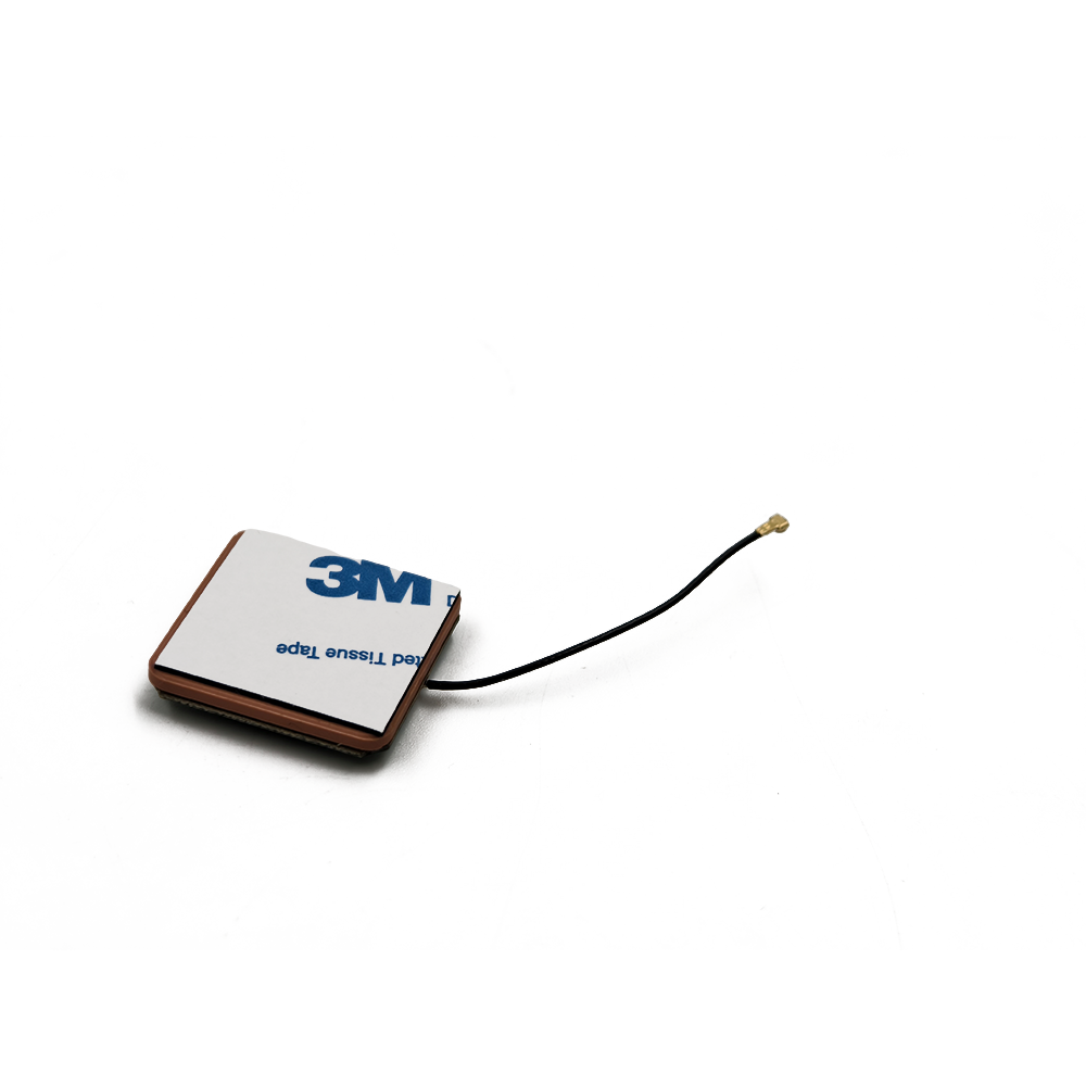
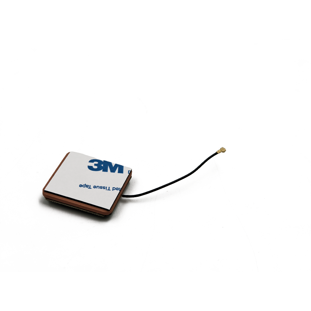
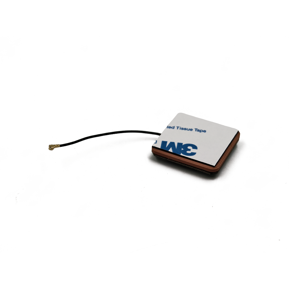
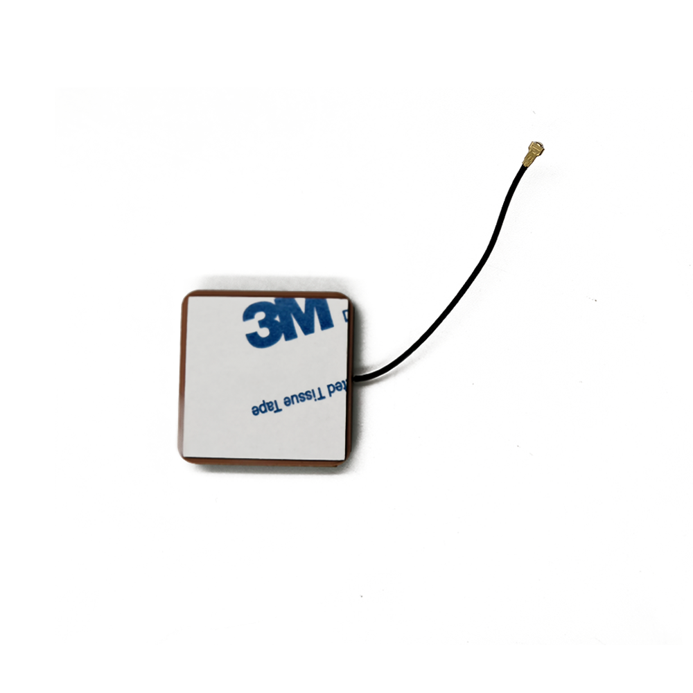
Overview
This device is a marvel of miniaturization and specialized engineering, designed to perform a single task with exceptional reliability: receive incredibly weak signals from satellites orbiting over 20,000 kilometers away and deliver a clean, amplified signal to the vehicle's GPS receiver, regardless of the environmental challenges. The name itself describes its core attributes:
Waterproof: It must operate flawlessly in all weather conditions—from blistering sun and sub-zero temperatures to torrential rain, high-pressure car washes, and road spray. Its sealing protects sensitive electronics from moisture ingress, which would cause corrosion and failure.
Active: Unlike a passive antenna that merely captures radio waves, an active antenna incorporates a Low-Noise Amplifier (LNA) positioned immediately after the radiating element. This amplifier is crucial because it boosts the extremely weak satellite signals before they are attenuated by the transmission line (the coaxial cable) that leads to the receiver. This preserves the Signal-to-Noise Ratio (SNR), which is critical for acquiring and maintaining a stable lock on satellites.
Ceramic: The radiating element is crafted from a specialized ceramic material with a high dielectric constant. This allows the antenna to be physically small while remaining electrically resonant at the GPS L1 frequency (1575.42 MHz). The ceramic patch is precisely engineered to be sensitive to Right-Hand Circularly Polarized (RHCP) signals, which is the polarization used by GPS satellites.
For Car: Its design is optimized for the unique automotive environment. This includes resilience to constant vibration and shock, operation across a vast temperature range (-40°C to +85°C is standard), and mitigation of multipath interference caused by signals reflecting off the car's body, other vehicles, and road surfaces.
The value of this component is immense. A poor-quality or poorly placed antenna can lead to slow time-to-first-fix (TTFF), inaccurate positioning, frequent signal dropouts in urban canyons or under tree cover, and a frustrating user experience. In safety-critical applications like eCall—where a vehicle automatically calls emergency services after a crash and transmits its location—antenna reliability can be a matter of life and death. For emerging autonomous driving functions, high-integrity positioning data is not a convenience but a fundamental sensor input, as critical as a camera or radar.
Therefore, the waterproof active GPS ceramic antenna is far more than a simple accessory. It is the primary gateway through which a vehicle understands its place in the world. It is the unsung hero that enables the convenience, safety, and efficiency features that consumers have come to expect, serving as the unwavering guide for modern mobility on an increasingly connected road network.
Design and Construction
The construction of a high-quality automotive GPS antenna is a meticulous process that balances electromagnetic performance with brutal environmental and mechanical durability. It is a multi-layered system where each component is carefully selected and integrated.
1. The Ceramic Patch Radiator: The Core Element
The heart of the antenna is the radiating element, a square or circular patch of ceramic substrate.
Material: The substrate is typically a ceramic-polymer composite with a high dielectric constant (εr), often between 20 and 40. This high εr reduces the wavelength within the material, allowing the patch to be physically smaller while remaining electrically resonant at 1.575 GHz. A common size is 25mm x 25mm x 4mm.
Design: The patch is metallized on its top surface, and this metal layer is etched into a specific pattern. The precise dimensions and shape of this patch, along with the properties of the ceramic, determine the antenna's resonant frequency, bandwidth, and polarization.
Polarization: The patch is designed to be sensitive to Right-Hand Circular Polarization (RHCP). This is crucial because GPS signals become circularly polarized after interacting with the atmosphere and ionosphere. RHCP reception helps to mitigate the negative effects of signal reflections (multipath), as reflections often reverse the polarization to Left-Hand Circular Polarization (LHCP), which the antenna rejects.
2. The Ground Plane: The Foundation of Performance
Beneath the ceramic patch lies a critical component: the ground plane. This is a continuous layer of conductive material (usually copper on the antenna's printed circuit board) that extends beyond the edges of the patch.
Function: The ground plane serves two primary purposes. First, it acts as an electrical reflector, shaping the antenna's radiation pattern into a directional hemispherical dome. This maximizes gain towards the sky (where the satellites are) and minimizes gain towards the Earth and the horizon. This upward-looking pattern is ideal for GPS applications.
Multipath Mitigation: Second, by reducing gain downwards, the ground plane helps reject signals reflecting off the car's bodywork, the road, and other objects. These delayed, reflected signals (multipath) are a primary source of positioning error.
3. The Low-Noise Amplifier (LNA): The Signal Booster
The "active" component is a semiconductor amplifier circuit located on a small PCB directly beneath or adjacent to the ceramic patch.
Purpose: The LNA's job is to amplify the faint satellite signals (which are buried in thermal noise) by a significant factor, typically 26 to 30 decibels (dB), while adding as little electronic noise of its own. Its quality is measured by its Noise Figure (NF); a lower NF (e.g., <1.5 dB) means a better SNR output.
Placement: Positioning the LNA as close as possible to the radiating element is a critical design rule. Any length of cable between the patch and the amplifier would introduce signal loss, which directly degrades the Noise Figure of the entire system. This integrated "pre-amplification" is what defines an active antenna.
4. The Band-Pass Filter: Keeping Interference Out
The RF path often includes a surface-acoustic wave (SAW) or ceramic band-pass filter.
Function: This filter is tuned to the GPS L1 band (and often other GNSS bands like GLONASS G1 or Galileo E1). It allows the desired satellite signals to pass through to the LNA while rejecting strong out-of-band interference from other services. In a car, potential interferers include cellular signals (4G/5G), VHF/UHF radios, Bluetooth, and Wi-Fi. Without this filtering, these strong signals could overload the LNA, causing desensitization or generating intermodulation products that corrupt the GPS band.
5. Power Supply: Bias Tee
The active antenna requires DC power for the LNA. This is ingeniously supplied through the same coaxial cable that carries the RF signal back to the receiver, a method known as DC bias or bias tee.
Implementation: A voltage (typically 3.3V or 5V) is supplied from the GPS receiver unit. Inside the antenna, an inductor (RF choke) directs this DC power to the LNA while blocking the RF signal from going back down the power line. A capacitor at the output blocks the DC voltage from entering the receiver's sensitive input, allowing only the amplified RF signal to pass.
6. Housing and Sealing: The Waterproof Shield
The entire assembly is encapsulated in a protective housing.
Radome: The top cover is a radome (radar dome) made of RF-transparent plastic, such as polycarbonate or ABS. It must be resistant to UV radiation to prevent yellowing and brittleness from sun exposure.
Waterproofing: To achieve an IP67 or IPX7 rating (immersion in 1 meter of water for 30 minutes), the housing is sealed using ultrasonic welding, gaskets, or potting compound. Potting—filling the entire housing with a waterproof epoxy or silicone gel—is highly effective as it provides a hermetic seal, protects components from moisture and corrosion, and acts as a shock absorber against vibration.
Mounting: Automotive antennas feature strong magnetic bases for temporary mounting or permanent adhesive or bolt-down options. The magnetic base must be strong enough to resist wind forces at high speeds.
This entire construction is a symphony of electrical and mechanical engineering, resulting in a robust, self-contained unit that can withstand the automotive environment while delivering a pristine GNSS signal.
Working Principles
The operation of the active GPS antenna is the first and most critical link in the chain of determining a vehicle's position. Its function is to act as a specialized signal capture and pre-processing unit.
1. Signal Reception: Capturing a Whisper from Space
GPS satellites transmit spread-spectrum signals centered on 1575.42 MHz. These signals are incredibly weak by the time they travel over 20,000 km to the Earth's surface, with a received power level significantly below the thermal noise floor (approximately -130 dBm). The ceramic patch antenna is optimized to efficiently capture these faint RHCP signals. Its radiation pattern ensures it is most sensitive to signals arriving from above (high elevation angles) and less sensitive to signals coming from the horizon or below, which are more likely to be reflections (multipath).
2. Front-End Filtering and Amplification
The captured RF energy is immediately passed to the integrated band-pass filter. This filter acts as a gatekeeper, rejecting powerful interfering signals from other transmitters that share the crowded radio spectrum. This is vital in a car, which is itself a hub of RF activity from key fobs, tire pressure monitors, and infotainment systems.
The filtered signal, now cleansed of much of its out-of-band interference, is fed directly into the Low-Noise Amplifier (LNA). The LNA performs the crucial task of boosting the signal amplitude by a factor of several hundred (e.g., 30 dB gain = 1000x voltage gain). It is designed to do this while contributing a minimal amount of additional electronic noise. The quality of this amplification is paramount; a poor LNA would amplify the noise as much as the signal, rendering the subsequent processing in the receiver difficult or impossible.
3. Transmission to the Receiver
The now-amplified signal is sent down the coaxial cable to the GPS receiver module, which is typically located within the vehicle's head unit or telematics unit. The use of an active antenna solves a major problem: coaxial cable has inherent loss (attenuation), which worsens at higher frequencies. For a several-meter-long cable run at 1.5 GHz, the loss could be 3-6 dB. Without the LNA at the antenna, the signal would arrive at the receiver even weaker than when it was captured, making acquisition very slow or impossible. The active antenna's LNA overcomes this cable loss, ensuring a strong signal is delivered to the receiver.
4. The Role of the GPS Receiver
The antenna's job ends at delivering the amplified RF signal. The receiver then takes over with a complex process:
Downconversion: The RF signal is mixed with a local oscillator signal to convert it to a lower, intermediate frequency (IF) that is easier to process.
Digitization: An Analog-to-Digital Converter (ADC) samples the analog IF signal.
Correlation: This is the core of GPS operation. The receiver generates replicas of the known GPS PRN (Pseudo-Random Noise) codes for each satellite. It then correlates these replicas with the digitized signal. When a match is found, it can lock onto that satellite's signal and precisely measure the signal's time of arrival.
Position Calculation: By measuring the time delay from at least four satellites, the receiver can trilaterate its precise position (latitude, longitude, altitude) and time.
The antenna does not calculate position; it is a sophisticated sensor that ensures the receiver has the highest quality raw material—the signal itself—with which to work. A high-quality active antenna provides a high Signal-to-Noise Ratio (SNR), which allows the receiver to achieve a faster Time-To-First-Fix (TTFF), maintain a stable lock in challenging environments, and produce more accurate and reliable position solutions.
Advantages and Challenges
-
The integration of an active GPS ceramic antenna into a vehicle offers clear benefits but also introduces specific design challenges that automotive engineers must carefully address.
Advantages:
Superior Signal Strength and Quality: The integrated LNA overcomes cable loss and provides a strong, clean signal to the receiver, which is the single biggest factor in overall system performance.
Improved Sensitivity and Acquisition Time: The high gain and low noise figure enable the receiver to detect and acquire satellites faster, especially when first turned on (cold start) or when signal conditions are poor.
Enhanced Performance in Challenging Environments: The robust design allows for reliable operation in low-signal areas such as urban canyons, under dense tree cover, and in adverse weather conditions, reducing dropouts.
Multipath Rejection: The combination of the ceramic patch's RHCP design and a proper ground plane effectively attenuates reflected signals, which are a major source of positioning error.
Design Flexibility: The small form factor and various mounting options (magnetic, adhesive, embedded) allow designers to place the antenna in an optimal location for satellite view (e.g., on the roof) without being constrained by cable loss.
Robustness and Reliability: The waterproof, potted, and ruggedized construction ensures a long service life despite exposure to extreme temperatures, vibration, humidity, and mechanical shock.
Challenges:
Power Dependency: As an active device, it requires a DC power supply from the receiver via the coaxial cable. A fault in this power circuit or in the antenna's LNA will result in a complete failure of the GPS system, whereas a passive antenna would still function (albeit poorly).
Potential for Overload and Interference: While designed to filter interference, extremely strong nearby transmitters (e.g., sitting next to a high-power radio tower) can still overload the LNA, causing desensitization and loss of lock. Careful filtering and shielding are required.
Placement and Integration Challenges: The antenna's performance is highly dependent on its location. Mounting it low on the dashboard, under a metallic tinted windshield, or next to other antennas can severely degrade performance. Finding a location with a clear view of the sky is often a compromise with vehicle aesthetics.
Cost and Complexity: An active antenna is more complex and expensive to manufacture than a passive component due to the added electronics (LNA, filter, components) and the rigorous environmental testing it must undergo.
Supply Chain and Component Sourcing: The global semiconductor shortage highlighted the vulnerability of active designs. A shortage of a specific LNA chip can halt production of millions of antennas, whereas a passive antenna has no such dependencies.
Despite these challenges, the performance advantages of the active antenna design are so significant that it has become the unequivocal standard for automotive-grade GPS applications.
Applications and Future Trends
-
The automotive active GPS antenna is a key enabler for a wide array of current and future vehicle functionalities that extend far beyond simple dashboard navigation.
Current Applications:
In-Vehicle Navigation Systems: Providing the core location data for map display and turn-by-turn routing.
Telematics and eCall: Modern vehicles are mandated in many regions to have eCall systems that automatically dial emergency services in the event of a severe crash and transmit the vehicle's location. The reliability of the GPS antenna is critical here.
Vehicle Tracking and Fleet Management: For commercial fleets, GPS data is used for routing optimization, driver behavior monitoring, asset security, and fuel usage analysis.
Usage-Based Insurance (UBI): Insurance companies use dongles or built-in systems that track driving habits (mileage, speed, braking, time of day) to calculate personalized insurance premiums.
Advanced Driver-Assistance Systems (ADAS): While not a primary sensor for real-time control, GPS data provides valuable contextual information. It can pre-load map data for upcoming curves, identify school zones, or help calibrate other sensors over long distances (e.g., dead reckoning between camera-based lane updates).
Future Trends:
Multi-Band and Multi-Constellation Support: The next generation of antennas will support all civilian signals from all available GNSS constellations (GPS L1/L2/L5, Galileo E1/E5/E6, GLONASS, BeiDou). Using multiple frequencies allows receivers to correct for ionospheric delay, enabling much higher accuracy (decimeter-level) without the need for ground-based corrections.
Integrated Antenna Modules (AIVs): The trend is towards "Antenna in Vehicle" modules where the GPS antenna is integrated into a larger unit that also combines cellular (4G/5G), Wi-Fi, Bluetooth, V2X, and AM/FM/DAB antennas. This simplifies roof design and cabling.
Enhanced Dead Reckoning (GNSS/INS): For tunnels and urban canyons where GPS signals are lost, the GPS will be tightly coupled with an Inertial Measurement Unit (IMU) containing gyroscopes and accelerometers. The antenna module itself may include a built-in IMU to provide more accurate heading and velocity data, creating a more robust and continuous positioning solution.
V2X and Autonomous Driving: For higher levels of automation, vehicles will need to communicate with each other (V2V) and with infrastructure (V2I). Highly accurate and reliable positioning is a foundational requirement for these V2X applications, mandating even more robust antenna systems.
"Smart" Antennas: Future antennas may incorporate basic diagnostic capabilities, able to report their own health status (e.g., LNA gain, connectivity) to the vehicle's network, enabling predictive maintenance.
The humble GPS antenna is evolving from a single-function component into a integrated, multi-frequency, multi-system hub that will play an even more critical role in the connected and autonomous vehicles of the future.
Conclusion
The waterproof active GPS ceramic antenna is a paradigm of focused engineering excellence. It is a component that performs a single, vital task with such reliability that it is often taken for granted. Yet, its role is absolutely indispensable in the ecosystem of the modern connected vehicle.
It is the critical first link in the data chain, the gatekeeper that ensures the vehicle's electronic brain has access to a high-fidelity stream of location information. Without it, a vast array of features—from the convenience of navigation and the efficiency of fleet management to the life-saving potential of eCall and the future promise of autonomous driving—would simply not be possible or would be severely compromised.
Its design is a perfect response to its mission: the ceramic patch and ground plane for optimal signal capture and multipath rejection; the LNA for overcoming signal loss; and the rugged, waterproof housing for surviving the harsh automotive environment. As vehicles become more connected and autonomous, the demands on this component will only grow, driving innovation towards multi-band support, deeper sensor integration, and even greater levels of reliability.
In the grand architecture of the automobile, it is a small, unassuming part. But it is the part that allows the vehicle to know itself, to understand its place on the road, and to safely and efficiently navigate the world. It is, truly, the unseen guide of modern mobility.


 Language
 En
En Cn
Cn Korean

 Home >


 18665803017 (Macro)


