

-
Products -PCBA Manufacturing RF Connectors RF Cable Assemblys Embedded Antennas External Antennas Positioning Chips and Modules
RF Connectors

RF Cable Assemblys
Embedded Antennas
External Antennas
Positioning Chips and Modules


 Language


Language


In the realm of high-precision surveying and geomatics, the Real-Time Kinematic (RTK) technique has become the gold standard for achieving centimeter-level accuracy in real-time. The entire premise of RTK, and other differential GNSS (Global Navigation Satellite System) methods, rests upon a simple yet critical concept: the use of a reference station, or base station, whose position is known with exceptional certainty. The integrity of every single centimeter-accurate measurement taken by a roving unit in the field is intrinsically tied to the quality and stability of this base station's data. At the heart of this trusted reference point lies a highly specialized piece of equipment: the surveying-grade RTK choke ring antenna.
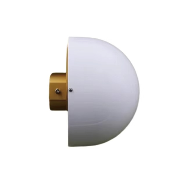
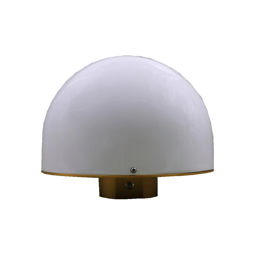
A choke ring antenna is not a mere signal receiver; it is a sophisticated electromagnetic instrument meticulously engineered for one primary purpose: to provide the most stable, reliable, and multipath-free GNSS observations possible. Its distinctive physical appearance—a large, heavy, circular antenna element surrounded by concentric, grooved metal rings—immediately signals its professional-grade status and specialized function. Unlike antennas designed for mobility, the choke ring is the anchor, the fixed point of truth in a world of satellite signal errors.
The "choke ring" itself refers to the series of concentric corrugated metal rings (typically three or four) that form a cavity around the actual antenna element, which is usually a patch antenna. These rings are not decorative; they are a profoundly effective passive filter for mitigating a pervasive and pernicious source of GNSS error known as multipath. Multipath occurs when a satellite's signal does not travel directly to the antenna but instead reflects off nearby surfaces—the ground, buildings, bodies of water, or even the equipment itself—before arriving. This reflected signal takes a longer path, introducing a delay that corrupts the precise timing measurements essential for high-accuracy positioning. For a base station, which is the benchmark for all rover measurements, any multipath error is catastrophic, as it is directly propagated to every rover in the network, systematically biasing all collected data.
The role of the base station antenna is therefore one of absolute purity and stability. While a rover antenna might be designed to be robust and compact for field use, the base station antenna is designed for perfection. It is typically deployed on a permanent or semi-permanent monument: a sturdy tripod, a pillar, or a deeply rooted geodetic marker that provides a stable and precisely known reference point. Its orientation is leveled, and its position is meticulously surveyed in, often using long observation sessions to minimize any residual error.
The applications for these antennas are exclusively professional and demand the highest possible data quality. They are the cornerstone of:
Geodetic Control Networks: Establishing the fundamental framework of precise coordinates for a region or country.
Construction Site Setup: Providing the accurate control points from which all machine control and building elements are positioned.
Precision Agriculture RTK Networks: Serving as the reference station for an entire farm or a community-based correction network.
Scientific Research: Monitoring crustal deformation, tectonic plate movement, and volcanic activity, where millimeter-level stability over years is required.
Photogrammetry and LiDAR Ground Control: Providing the exact ground control points necessary to geo-reference aerial and satellite imagery with extreme accuracy.
In essence, the surveying RTK choke ring antenna is the silent guardian of precision. It is the unassuming, static sentinel that ensures the chaotic and error-prone signals from space are tamed, filtered, and converted into a pristine stream of correction data, thereby enabling an entire ecosystem of mobile precision to function with confidence. It represents the ultimate expression of the principle that for a system to be accurate, its foundation must be unshakable.
The design of a surveying-grade choke ring antenna is a masterclass in electromagnetic engineering, mechanical stability, and material science. Every aspect of its construction is meticulously chosen and optimized to achieve a single goal: the acquisition of the cleanest possible GNSS signal by maximally rejecting multipath interference.
The Choke Ring Assembly:
The most iconic feature is the choke ring structure itself. This consists of several concentric, circular troughs (rings) of precise depth and width machined from a single block of high-conductivity metal, typically aluminum, which is often coated with a protective layer to prevent corrosion. The depth of these grooves is critically important; it is designed to be approximately one-quarter of the wavelength of the target GNSS frequencies (e.g., ~4-5 cm for the GPS L1 band).
This quarter-wave dimension is the key to its operation. For electromagnetic waves, a quarter-wave deep groove acts as a high-impedance surface at its resonant frequency. When a horizontally polarized (the primary polarization of ground-reflected multipath) radio wave attempts to travel across the rings, it encounters this high-impedance surface. This effectively "chokes" the current induced on the metal surface, preventing it from propagating. The rings thus create a electrical null zone, attenuating signals that arrive at low elevation angles—precisely where multipath reflections originate. The direct signals from satellites above, which have a significant vertical polarization component, pass through with minimal attenuation.
The Antenna Element:
At the center of this protective ring structure lies the active antenna element, almost invariably a dielectric-loaded patch antenna. This patch is engineered for superior performance:
Precise Phase Center: The most critical characteristic of a geodetic antenna is the stability of its Phase Center—the electrical point from which the radiation appears to emanate. Any movement or variation of this point with signal direction or frequency introduces measurement error. The patch and its feed network are designed to have a phase center that is as consistent as possible across the entire hemisphere and across all GNSS frequency bands (L1, L2, L5, etc.). This stability is meticulously calibrated by the manufacturer.
Zenith-Optimized Gain Pattern: The radiation pattern is shaped to provide high gain towards the zenith and upper elevations, where the strongest and most direct satellite signals are located, while the choke rings suppress the low-elevation gain.
Multi-Band Support: The patch is a complex structure, often involving stacked elements or carefully engineered slots, to resonate efficiently at multiple GNSS frequencies (e.g., GPS L1/L2/L5, GLONASS G1/G2, Galileo E1/E5a/E5b, BeiDou B1/B2/B3). This allows the base station to track all available signals, providing robustness and enabling advanced error mitigation like ionospheric delay calculation.
Low-Noise Amplifier (LNA) and Filtering:
As with all active GNSS antennas, a crucial component is the internal Low-Noise Amplifier (LNA). Its quality is paramount. It must provide high gain (e.g., 40-50 dB) to overcome cable losses while adding an absolute minimum of internal electronic noise (Noise Figure often < 2 dB). This ensures the incredibly weak satellite signals are amplified without being drowned in thermal noise. Advanced bandpass filters are integrated before the LNA to reject powerful out-of-band interference from cellular, WiFi, and radio transmitters, which are common in many environments.
Physical Construction and Environmental Sealing:
A base station antenna is built for permanence and resilience. The entire assembly—patch, rings, and electronics—is housed under a rugged radome. This radome is made from a material that is virtually transparent to RF signals (low dielectric constant and loss tangent), such as high-grade polycarbonate or ceramic-loaded composites. It is designed to be extremely rigid and is treated to be UV-resistant, preventing yellowing and degradation over decades of sun exposure.
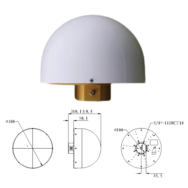
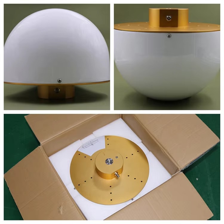
The unit is hermetically sealed using high-quality O-rings and gaskets, achieving at least an IP67 rating to protect the sensitive internal electronics from moisture, dust, and condensation. The base of the antenna is a heavy, solid metal plate that provides both a stable mechanical interface and an integral ground plane for the patch element. This base features a standard mounting thread (typically 5/8"-11 or M10x1.5) for attachment to a survey tripod, pillar, or permanent monument.
The internal electronics are often potted—encapsulated in a thermally stable, rigid, or flexible epoxy resin. This potting compound secures components against vibration, provides a moisture barrier, and aids in heat dissipation from the LNA. The cable entry is another critical point, typically using a robust strain-relief and a sealed connector (e.g., TNC, SMA) or a molded cable assembly to prevent water ingress.
In summary, the construction of a choke ring antenna is an exercise in minimizing every conceivable source of error, from electromagnetic multipath to thermal electronic noise, and from mechanical instability to environmental degradation. It is a precision instrument crafted for a singular, critical purpose.
The working principle of a choke ring antenna is elegantly rooted in fundamental electromagnetic theory, transforming its physical structure into a highly effective spatial filter. Its operation can be understood by contrasting the desired direct signals with the undesired multipath signals and observing how the antenna treats each differently.
The Nature of Multipath and Direct Signals:
A direct signal from a satellite high in the sky arrives at the antenna with a specific polarization and from a high elevation angle. GNSS signals are Right-Hand Circularly Polarized (RHCP). When a perfectly RHCP signal reflects off a surface, its polarization reverses and becomes predominantly Left-Hand Circularly Polarized (LHCP). Furthermore, reflected signals almost always arrive at low elevation angles, close to the horizon.
The Function of the Choke Rings:
The concentric corrugated rings act as a ground plane of non-uniform reactance. Their quarter-wave depth creates a structure that presents a very high surface impedance to incoming radio waves at the design frequency. This high impedance has a profound effect on surface currents:
Suppressing Surface Waves: Multipath signals, arriving at a shallow angle, interact tangentially with the metal surface of the antenna. They induce currents that would normally travel along a smooth ground plane and interfere with the direct signal received by the patch element. The choke rings disrupt this entirely. The high impedance of the rings prevents these horizontal surface currents from flowing. The energy of the multipath signal is effectively reflected away or dissipated, preventing it from reaching the antenna element.
Preserving Direct Signals: Direct signals from high-elevation satellites arrive with a significant vertical component to their propagation. This vertical component does not excite the same horizontal surface currents. Furthermore, the circular polarization of the direct signal is better matched to the antenna element. The choke rings have a negligible blocking effect on these desired signals, allowing them to pass through unimpeded to be received by the patch antenna.
In essence, the choke rings create an "electromagnetic moat" around the antenna. Signals trying to crawl along the ground (multipath) cannot cross the moat, while signals descending from the sky (direct signals) pass over it without issue.
The Role of the Patch Antenna and LNA:
The central patch antenna is itself optimized for this environment. Its radiation pattern is designed to be slightly upward-looking, complementing the choke rings' suppression of low-angle signals. It is meticulously engineered to have a stable phase center. This is critical because the RTK technique relies on measuring the phase of the carrier wave. If the electrical point from which this phase is measured (the phase center) moves depending on the direction of the incoming signal or the frequency, it introduces a systematic error into the carrier-phase measurement. A stable phase center ensures that the measured phase delay is due solely to the satellite-to-antenna geometry, not an artifact of the antenna itself.
Once the patch captures the purified RF energy, the internal Low-Noise Amplifier (LNA) performs its vital task. The signals are incredibly weak, and the LNA must boost their power by orders of magnitude while adding a bare minimum of its own electronic noise. A high-gain, low-noise-figure LNA is what allows the receiver to maintain lock on satellites even in less-than-ideal conditions and to utilize weaker signals from satellites at lower elevations, increasing the overall number of available satellites.
The Output: A Pristine Data Stream:
The final output of the antenna system is a clean, amplified RF signal delivered through the coaxial cable to the GNSS receiver. This signal has been:
Spatially filtered by the choke rings to remove low-angle multipath.
Polarization filtered, as the patch is more sensitive to RHCP, further rejecting the LHCP reflected signals.
Amplified with minimal noise corruption.
Band-pass filtered to remove out-of-band RF interference.
The receiver can then use this pristine signal to generate the raw observation data (carrier-phase, pseudorange) that is virtually free of locally induced multipath error. This forms the basis for generating the high-integrity correction data that is broadcast to the rovers, making the entire RTK system possible. The base station antenna doesn't just receive signals; it curates them.
The choke ring antenna is the undisputed performance champion for base station applications, but its superiority comes with specific trade-offs that must be carefully considered in any system design.
Advantages:
Unrivaled Multipath Mitigation: This is its primary and most significant advantage. No other antenna technology can match the choke ring's ability to suppress low-elevation, ground-reflected multipath. This leads to the most stable carrier-phase observations possible, which is the direct foundation of high-precision RTK positioning.
Exceptional Phase Center Stability: Geodetic-grade choke ring antennas are renowned for their highly stable and well-defined phase center. This minimizes a source of systematic error that is often a limiting factor in achieving the highest levels of accuracy (millimeter-level). The phase center variation (PCV) across different frequencies and elevation angles is meticulously measured and published by manufacturers in ANTEX files, allowing survey processing software to correct for even these tiny residual effects.
Superior Data Quality and Integrity: The combined effect of multipath rejection and phase center stability results in a significantly lower measurement noise and higher data integrity. This provides greater confidence in the base station's coordinates, faster and more reliable integer ambiguity resolution for the rover, and ultimately, more accurate and repeatable survey results.
Robustness in Challenging Environments: The antenna excels in environments prone to severe multipath, such as areas with reflective ground surfaces (pavement, water), near buildings, or on vibrating structures. Its design makes it the only choice for permanent installation sites where the environment cannot be changed.
Multi-Frequency Performance: High-end models are optimized for all modern GNSS signals, making them future-proof and capable of leveraging the full satellite constellation for improved reliability and faster convergence times.
Challenges and Considerations:
Size, Weight, and Bulk: This is the most obvious drawback. Choke ring antennas are large, heavy, and cumbersome. They are not portable in any practical sense for rapid, solo field work. Transporting them requires a dedicated case, and setting them up requires a sturdy, stable tripod or permanent monument.
Cost: They are the most expensive type of GNSS antenna by a significant margin. The precision machining, high-quality materials, and rigorous calibration processes involved in their manufacture command a premium price. This makes them a capital investment.
Deployment Practicality: Their size and weight make them less suitable for rapid, temporary base station setups. For many topographic or construction applications where the base is moved daily, a smaller, lighter geodetic antenna (without full choke rings) may be a more practical compromise.
Wind Loading: The large physical profile acts like a sail in windy conditions. This can introduce vibration and movement into the tripod, potentially affecting the phase measurements. For the highest precision, a well-guyed tripod or a permanent pillar is essential to mitigate this effect.
Calibration Dependency: To achieve their ultimate performance, they require precise calibration data (the ANTEX file) to be applied in the post-processing software. Using the antenna without applying its specific phase center corrections can actually introduce error, negating its benefit if the processing workflow is not configured correctly.
In conclusion, the choke ring antenna offers unparalleled performance for applications where data quality is the non-negotiable top priority. However, its advantages are balanced against significant practical limitations in size, cost, and portability. The choice to use one is a conscious decision to prioritize ultimate accuracy over operational convenience.
The application of surveying RTK choke ring antennas is specialized, reflecting their role as the foundation for the most demanding precision positioning tasks. They are deployed wherever the cost of error is unacceptably high.
Applications:
Geodetic Control Networks: This is their classic and most critical application. National mapping agencies, geological surveys, and academic institutions use them to establish and maintain fundamental geodetic reference frames. These networks require extreme long-term stability and millimeter-level repeatability, which is only possible with the multipath rejection and phase center stability of choke ring antennas.
Scientific Monitoring: They are essential tools in geophysics for monitoring crustal deformation, tectonic plate motion, subsidence, and volcanic inflation. Deployed in permanent arrays, these antennas can detect movements of a few millimeters per year, providing crucial data for earthquake and hazard studies.
Permanent Reference Station Networks (CORS): Continuously Operating Reference Station (CORS) networks are the infrastructure that provides RTK corrections over a wide area via the internet or cellular networks. Every station in a professional CORS network will invariably use a choke ring antenna to ensure the highest quality and reliability of the correction data stream for all users across the network.
High-Stakes Engineering and Construction: For major infrastructure projects—tunnels, bridges, large dams, and particle accelerators—where millimeter-level alignment is critical over long distances, choke ring antennas are used to establish the primary project control points. They provide the unshakable foundation from which all other measurements are derived.
Calibration and Metrology: They are used as the reference standard for calibrating other GNSS equipment and for high-precision metrology applications where the precise relationship between multiple points must be established over time.
Future Trends:
Integration with Multi-Constellation and Multi-Frequency: Future designs will continue to evolve to perfectly handle all signals from all constellations (GPS, GLONASS, Galileo, BeiDou, QZSS, NAVIC) and all frequencies (L1, L2, L5, L6, etc.). The antenna element and choke ring design will be optimized for this wider bandwidth.
Miniaturization and Advanced Materials: While unlikely to become "small," research continues into achieving similar multipath rejection performance with more compact ring structures or using advanced metamaterials that can manipulate electromagnetic waves in novel ways to create more efficient spatial filters.
Tighter Integration with AI and Processing: The antenna itself will remain a passive component, but the systems around it will get smarter. Real-time processing software will use advanced algorithms to further identify and filter any residual multipath that the physical antenna cannot eliminate, and to dynamically model phase center variations.
Enhanced Robustness and Monitoring: Future antennas may include integrated sensors to monitor their own health and environment (e.g., tilt sensors to detect movement, humidity sensors inside the radome). This "self-awareness" would provide quality control metrics for the data they are producing, which is critical for unattended CORS stations.
Focus on Absolute Phase Center Calibration: The demand for millimeter and sub-millimeter accuracy will drive even more rigorous and comprehensive antenna calibration processes, possibly involving field-based calibration techniques and more sophisticated anechoic chamber measurements to model every nuance of the antenna's performance.
Conclusion
The surveying RTK choke ring antenna is a masterpiece of targeted engineering. It is a technology that has remained fundamentally consistent for decades because its underlying principle—using physical geometry to manipulate electromagnetic waves—is so effective and difficult to surpass with alternative methods. It represents a philosophy where performance is paramount, and compromises for the sake of size, cost, or convenience are simply not an option.
In the entire chain of high-precision positioning, from the satellite transmitter to the rover's final calculated point, the base station antenna is the most critical physical component on the ground. It is the first and most important line of defense against the most common and damaging source of error: multipath interference. By providing a stream of exceptionally pure and stable data, it allows the sophisticated algorithms of the RTK engine to perform at their best, resolving integer ambiguities quickly and reliably.
Its role is that of an unwavering guardian. It stands firm, often for years on end, through all weather conditions, providing the trusted reference upon which an entire mobile workforce of surveyors, engineers, and scientists depends. While smaller and more portable antennas have their place for rover applications, the base station's mandate is different. Its mandate is absolute integrity.
The continued evolution of GNSS, with new signals and constellations, will not diminish the need for this integrity; it will only heighten it. As we push the boundaries of accuracy into the sub-centimeter realm for autonomous systems and scientific discovery, the demand for the flawless data that only a well-designed choke ring antenna can provide will only grow. It is, and will remain, the unshakable foundation of geospatial truth, the silent benchmark against which all other measurements are judged.

 86 0755 2819 9597
Lucy Yang | lucy.y@toxutech.com
Nicole Li | nicole@toxutech.com
Dotty Zhao | sales04@toxutech.com
Global Business Director / Sales Team / Global Operations


 En
En Cn
Cn Korean
 Home >


