

-
Products -PCBA Manufacturing RF Connectors RF Cable Assemblys Embedded Antennas External Antennas Positioning Chips and Modules
RF Connectors

RF Cable Assemblys
Embedded Antennas
External Antennas
Positioning Chips and Modules


 Language


Language


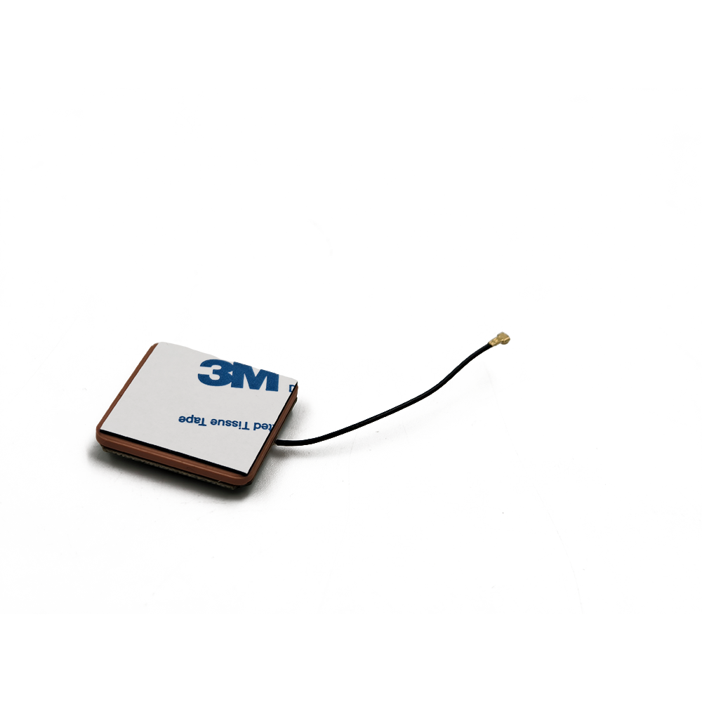
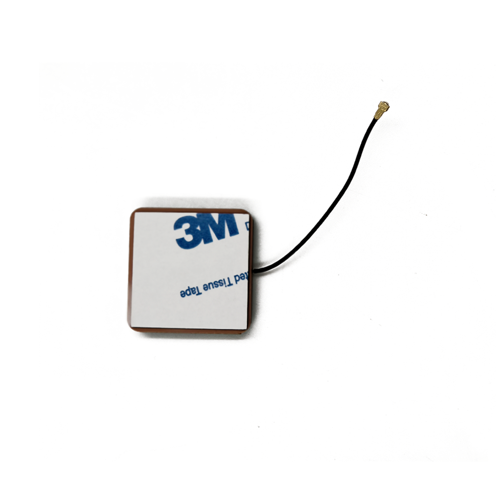

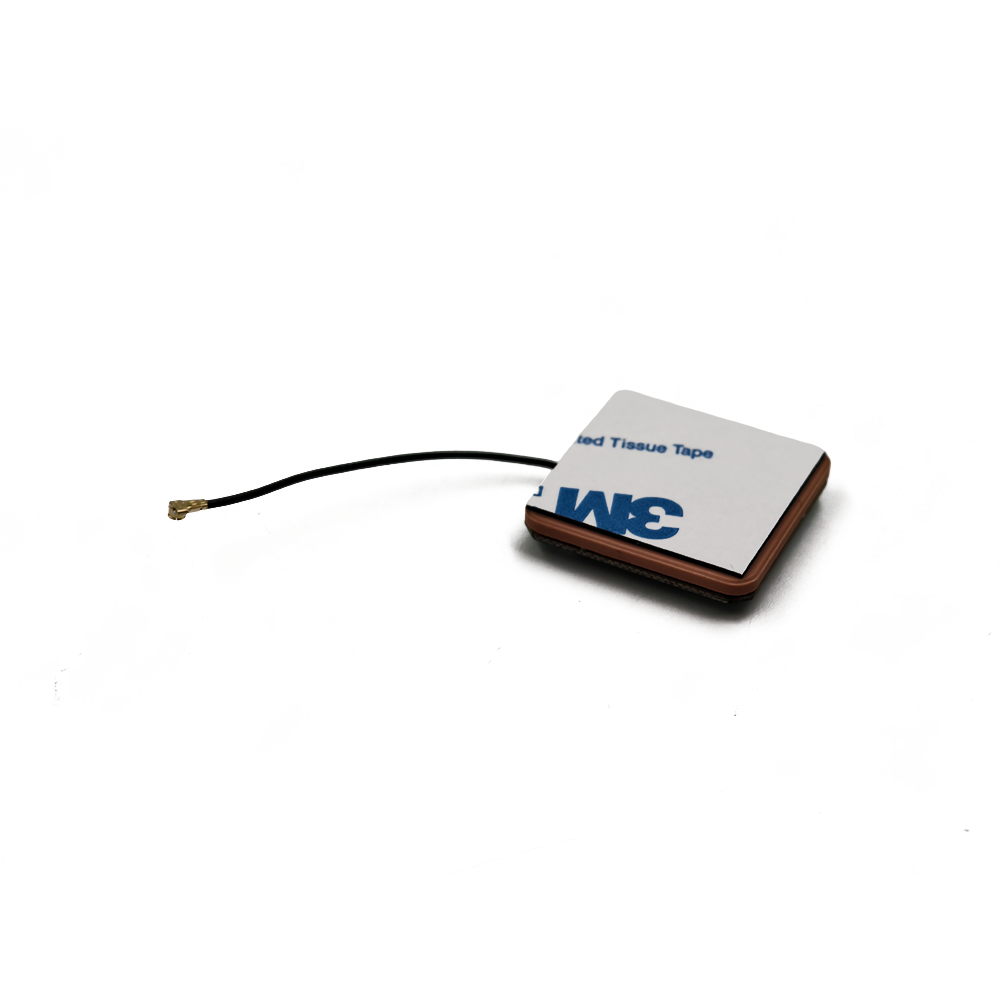

The Global Positioning System (GPS) has evolved from a specialized military technology into an indispensable utility underpinning modern civilization. From navigating city streets to synchronizing financial networks and managing global logistics, GPS provides precise timing and location data. At the heart of this ubiquitous functionality in consumer and industrial electronics is a critical, yet often overlooked component: the GPS antenna. Among the various types, the small-size ceramic patch antenna module has emerged as the dominant form factor, enabling the miniaturization and mass adoption of GPS technology in devices ranging from smartphones and smartwatches to drones and asset trackers.
A GPS antenna module is fundamentally a transducer that converts electromagnetic radio waves—transmitted at microwave frequencies from a constellation of satellites orbiting the Earth—into electrical signals that a GPS receiver can process. The "small-size ceramic patch" descriptor breaks down into its key characteristics: "small-size" refers to its compact physical dimensions, typically ranging from 10mm x 10mm to 25mm x 25mm with a height of just 2mm to 4mm, making it ideal for space-constrained applications. "Ceramic" denotes the high-dielectric material, often alumina (Al2O3) or a barium-strontium-titanate blend, which forms the substrate. This material is crucial as its high permittivity allows the physical size of the antenna to be significantly smaller than the wavelength of the incoming signal. "Patch" describes the radiating element itself—a metallic (often silver or copper) patch etched or printed onto the ceramic substrate, which resonates at the target GPS frequency of 1575.42 MHz (L1 band).
The evolution towards this design is a story of engineering trade-offs aimed at achieving optimal performance within severe physical and economic constraints. Earlier external active antennas, while high-performing, were impractical for portable devices. The ceramic patch antenna offered a solution by providing a robust, low-profile, and manufacturable platform that could be surface-mounted directly onto a printed circuit board (PCB) like any other electronic component. This integration simplifies assembly, reduces costs, and improves reliability.
A modern GPS antenna module is rarely just a passive ceramic patch. It is typically a "Active Antenna Module," integrating several key components into a single package. The core is the ceramic patch radiator. Beneath it, the module contains a ground plane, which is essential for the antenna's directional radiation pattern. Integrated into the module or located immediately adjacent on the PCB is a low-noise amplifier (LNA). The LNA is critical because GPS signals are incredibly weak by the time they traverse over 20,000 kilometers from space to the Earth's surface, arriving at power levels below the thermal noise floor (-130 dBm). The LNA amplifies these faint signals while adding minimal self-generated noise (a key parameter called Noise Figure), preparing them for transmission via a coaxial cable or trace to the GPS receiver chip. The module also often includes a band-pass filter to reject out-of-band interference from cellular, Wi-Fi, and Bluetooth radios that are typically collocated in modern devices.
The proliferation of these modules is directly linked to the demands of the Internet of Things (IoT) and personal mobile devices. Their small size allows engineers to embed precise positioning capabilities into virtually any object. Furthermore, the ceramic material provides environmental stability, protecting the sensitive radiating element from humidity, dust, and mechanical shocks, ensuring consistent performance over the product's lifetime. In summary, the small-size ceramic patch GPS antenna module is a masterpiece of microwave engineering that has successfully balanced the competing demands of performance, size, cost, and manufacturability, thereby acting as a fundamental enabler for the location-aware world we live in today.
The design and construction of a small-size ceramic patch GPS antenna module is a sophisticated process involving advanced materials science, electromagnetic theory, and precision manufacturing. It is a multi-layered structure where each layer and material choice is meticulously optimized to achieve the desired resonant frequency, bandwidth, radiation pattern, and impedance matching.
Core Materials: The Ceramic Substrate
The choice of substrate material is the most critical decision, as it dictates the antenna's size and performance characteristics. Engineers use ceramic materials with a high relative dielectric constant (εr), typically between 20 and 40. Common materials include:
Alumina (Al2O3): A workhorse material with good mechanical strength, thermal stability, and a dielectric constant around 9.9. For smaller sizes, higher εr materials are preferred.
Barium Strontium Titanate (BaSrTiO3) and other proprietary ceramic blends: These are engineered to have very high dielectric constants (εr ~20-40). The high εr effectively slows down the propagation of the electromagnetic wave within the material, reducing the wavelength and thus allowing the resonant patch to be physically much smaller. For instance, the wavelength in free space for the GPS L1 frequency is approximately 19 cm. A high-εr ceramic can reduce the required patch size to just 1-2 cm. The trade-off is that higher εr materials often have higher loss tangents (tan δ), which can reduce antenna efficiency, and they can be more brittle and costly.
Layer-by-Layer Architecture
A typical multilayer ceramic patch antenna is constructed like a sandwich:
Top Layer (Radiating Patch): This is a layer of highly conductive material, usually silver or copper, printed onto the top surface of the ceramic substrate. Its dimensions (length and width) are precisely calculated to determine the resonant frequency. The patch is typically square or rectangular, though slight modifications are sometimes made to optimize performance.
Ceramic Substrate Layer: This is the core dielectric body that provides the mechanical support and the high-permittivity environment that enables miniaturization.
Ground Plane Layer: A continuous layer of metal (again, silver or copper) printed on the bottom surface of the ceramic substrate. This ground plane is essential for the antenna operation. It defines the antenna's directional pattern (broadside) and shields it from noise and interference emanating from the electronics below it on the device's main PCB.
Feeding Mechanism: Getting the signal from the radiating patch to the receiver is a key design challenge. The two most common methods are:
Probe Feeding: A conductive pin (probe) is connected from the ground plane through a hole in the substrate (a via) to the patch. The point of connection controls the input impedance.
Aperture-Coupled Feeding: A more advanced technique where the patch is excited electromagnetically rather than directly. The patch is on one substrate layer, and a separate feedline is on a different layer below it, separated by the ground plane which has a small slot (aperture) etched into it. Energy couples from the feedline through the slot to the patch. This method offers better bandwidth and isolates the feed network from the radiator.
Integrated Components (Active Module): In an active antenna module, the Low-Noise Amplifier (LNA) and often a surface acoustic wave (SAW) filter are integrated into the package. The antenna feed is connected directly to the input of the LNA, which is then powered through a DC bias line. The output of the LNA is the RF output port of the module. This integration must be carefully shielded to prevent the amplifier's output from coupling back into the antenna input and causing oscillation.
Design Considerations and Simulation
The design process is heavily reliant on 3D electromagnetic simulation software like ANSYS HFSS or CST Studio Suite. Engineers model the entire structure—patch dimensions, substrate thickness and εr, feed location, and nearby objects—to simulate performance parameters before physical prototyping.
Key performance parameters optimized during design include:
Return Loss (S11): Measures how much power is reflected back from the antenna. A value below -10 dB (often targeted at -15 to -20 dB at 1575.42 MHz) indicates good impedance matching, meaning most power is accepted by the antenna.
Bandwidth: The range of frequencies over which the return loss remains below -10 dB. GPS requires only a few MHz of bandwidth, but designs often aim for wider bandwidth to account for manufacturing tolerances and to cover other GNSS constellations (like GLONASS, Galileo, BeiDou) which operate at slightly offset frequencies.
Gain and Radiation Pattern: The desired pattern is a hemispherical (or "bulge") pattern directed towards the sky. The gain is typically between 2-5 dBiC (decibels relative to an isotropic circularly polarized antenna). The pattern should have a wide beamwidth to receive signals from satellites across the sky.
Axial Ratio: A measure of the purity of the antenna's circular polarization. GPS signals are right-hand circularly polarized (RHCP). A low axial ratio (ideally < 3 dB) is critical for rejecting reflected (left-hand polarized) signals and multipath interference.
Manufacturing
The manufacturing process resembles that of multilayer ceramic chip capacitors. It involves tape-casting ceramic slurry into thin sheets, screen-printing metallic electrodes and patterns onto these sheets, laminating the layers together, and then firing them in a high-temperature kiln to form a monolithic, sintered ceramic block. The components are then singulated from the larger panel, tested, and packaged. This process allows for high-volume, low-cost, and highly consistent production.
The operation of a ceramic patch GPS antenna module is a elegant application of electromagnetic resonance and wave polarization, designed to efficiently capture extremely weak signals from space.
Fundamental Resonance: The Half-Wavelength Patch
At its core, the patch antenna operates as a resonant cavity. The metal patch and the larger ground plane beneath it form two parallel conducting surfaces, with the ceramic substrate acting as the dielectric between them. This structure forms a leaky resonant cavity. The fundamental mode of operation is when the length of the patch (L) is approximately half of the wavelength within the dielectric material (λ_d). The wavelength in the dielectric is given by λ_d = λ_0 / √ε_r, where λ_0 is the free-space wavelength and ε_r is the relative dielectric constant of the ceramic. This equation shows why high-ε_r ceramics are used: they drastically reduce λ_d, and consequently the required physical length L.
When operating at this resonant frequency, a standing wave of current is established on the patch. The electric field is oriented perpendicular to the patch surface, fringing at the edges. These fringing fields are the primary source of radiation. The radiation pattern is directional, broadside to the patch (perpendicular to its plane), which is ideal for pointing towards the sky in most applications.
Circular Polarization
GPS satellites transmit signals that are Right-Hand Circularly Polarized (RHCP). This means the electric field vector of the electromagnetic wave rotates clockwise as it propagates towards the receiver. RHCP is used because it is less affected by certain atmospheric conditions and, crucially, it helps mitigate multipath interference. Multipath occurs when a signal reflects off a surface (like a building or the ground) before reaching the antenna. Upon reflection, the polarization of the wave often reverses, becoming predominantly Left-Hand Circularly Polarized (LHCP).
A receiving antenna that is also RHCP will be naturally "deaf" to these reflected LHCP signals, providing inherent rejection of a significant source of positioning error. Achieving circular polarization in a patch antenna is accomplished by slightly perturbing the resonant structure to excite two orthogonal modes with a 90-degree phase difference between them. The two most common techniques are:
Single-Feed with Truncated Corners: The simplest method. Two opposite corners of the square patch are truncated (cut off). This distortion creates two degenerate orthogonal modes that are fed simultaneously by a single probe feed. The asymmetry introduces a phase shift, resulting in circular polarization.
Dual-Feed with 90° Hybrid Coupler: A more complex but higher-performance method. The patch is fed at two orthogonal points. A external 90-degree hybrid coupler circuit is used to split the signal from the LNA and feed the two points with a precise 90-degree phase shift, which directly generates the required circular polarization. This method allows for better control of the axial ratio.
The Role of the Active Components (LNA and Filter)
The passive ceramic patch alone is insufficient for modern applications due to the extreme weakness of GPS signals. The active components are therefore integral to its working principle.
Low-Noise Amplifier (LNA): The signal from the satellite arrives at the Earth's surface with a power level of approximately -125 to -130 dBm, which is below the thermal noise floor. The primary job of the LNA is to amplify this faint signal (typically by 15 to 28 dB) while adding the absolute minimum amount of its own noise, quantified by its Noise Figure (NF). A typical GPS LNA has a NF of 0.8 to 1.2 dB. This "gain boost" is essential to raise the signal above the noise floor of the subsequent GPS receiver chip, overcoming the losses in the coaxial cable or transmission line that connects the antenna module to the receiver.
Band-Pass Filter: Often a Surface Acoustic Wave (SAW) filter is integrated before or after the LNA. Its function is to reject strong out-of-band interference. In a smartphone, powerful transmitters for GSM, LTE, 5G, Wi-Fi, and Bluetooth are located mere centimeters away. Without a filter, these strong signals could overload the sensitive GPS receiver, causing desensitization and making it impossible to acquire the weak satellite signals. The filter allows only the ~1550-1610 MHz GNSS band to pass through.
In operation, the electromagnetic wave from the satellite induces a tiny current on the RHCP ceramic patch. This current is carried to the input of the LNA, where it is amplified. The filter ensures only the desired frequencies are amplified. The boosted, clean signal is then sent via the output port to the GPS receiver for digitization and correlation processing to calculate position, velocity, and time (PVT).
The widespread adoption of small-size ceramic patch GPS antenna modules is a testament to their significant advantages. However, like any technology, they come with inherent challenges that engineers must constantly work to overcome.
Advantages:
Compact Size and Low Profile: This is their defining advantage. The use of high-dielectric ceramic substrates allows for a radical reduction in footprint and height compared to traditional antennas like helices or dipoles. This enables integration into sleek, portable consumer devices where internal real estate is fiercely contested.
Robustness and Durability: The monolithic ceramic structure is inherently rigid and resistant to environmental factors. It is not susceptible to deformation like some flexible printed antennas, and the materials are often resistant to moisture, corrosion, and temperature variations, ensuring long-term reliability.
Ease of Integration and Manufacturing: Designed as surface-mount technology (SMT) components, they can be automatically picked and placed onto a PCB using standard assembly lines, significantly reducing manufacturing complexity and cost compared to assembling and housing external antennas.
Directional Radiation Pattern: The pattern is ideally suited for most navigation applications. The broadside, upward-looking hemisphere pattern maximizes gain towards the sky (where the satellites are) and provides inherent shielding from noise generated by the device's own electronics located below the ground plane.
Excellent Circular Polarization: They can be designed to achieve very low axial ratios, providing high polarization purity for effective multipath rejection, which is critical for accuracy in urban environments.
Cost-Effectiveness at Scale: While the ceramic materials and design process can be expensive initially, the manufacturing process is highly scalable. Once in mass production, the unit cost becomes very low, making it economically viable for high-volume consumer products.
Challenges and Limitations:
Inherently Narrow Bandwidth: The high-Q resonant nature of the patch antenna results in a relatively narrow bandwidth. While sufficient for single-band GPS L1, this becomes a challenge for modern multi-GNSS receivers that need to support GPS L1/L2/L5, Galileo E1/E5, BeiDou B1/B2, etc., which span a much wider frequency spectrum. Designers must use techniques like thicker substrates or aperture coupling to broaden the bandwidth, often at the expense of size.
Size-Performance Trade-off: The very principle that enables miniaturization is also a limitation. Higher dielectric constants allow for smaller sizes but also increase losses (due to higher loss tangent) and reduce bandwidth. There is a constant and fundamental trade-off between the physical size, efficiency, and operational bandwidth of the antenna.
Ground Plane Dependence: The performance of a patch antenna is highly dependent on the size and quality of the ground plane it is mounted on. In a device, the antenna's ground plane is not the tiny one inside the module but the device's PCB itself. The size and shape of the host PCB can detune the antenna, alter its radiation pattern, and affect its impedance matching. This means an antenna module must be re-characterized and often re-tuned for each new product design, adding to development time.
Susceptibility to Nearby Objects (De-tuning): The antenna's performance is sensitive to the surrounding environment. The presence of metal components, batteries, plastic housings, and even the user's hand can detune the resonant frequency and distort the radiation pattern. This is a major challenge in smartphone design, requiring extensive simulation and testing in the final product enclosure.
Limited Performance at Low Elevation Angles: While the hemispherical pattern is good for overhead satellites, the gain drops off significantly at low elevation angles (closer to the horizon). This can make it difficult to acquire and track satellites in deep urban canyons or under heavy foliage, where the direct line-of-sight path may be blocked and only signals bouncing from low angles are available.
Fragility: While robust against environmental factors, ceramic substrates are brittle and can be susceptible to mechanical shock, such as drops onto a hard surface, which could cause cracking and failure.
The unique blend of size, performance, and cost has cemented the small ceramic patch GPS antenna's role across a vast and growing spectrum of applications. Concurrently, research and development are pushing the boundaries of its capabilities to meet future demands.
Current Applications:
Consumer Electronics: This is the highest-volume application. Every smartphone, tablet, smartwatch, fitness tracker, and digital camera with location services relies on a miniature ceramic patch antenna.
Automotive: Used extensively in telematics control units (TCUs), stolen vehicle tracking systems, emergency call (eCall) systems, and in-dash navigation units. They are also critical for emerging Advanced Driver-Assistance Systems (ADAS) and autonomous vehicle testing, which require highly reliable positioning.
Internet of Things (IoT) and Asset Tracking: This is a massive growth area. The modules are embedded in logistics trackers, wildlife collars, agricultural sensors, smart meters, and wearable health monitors, providing real-time location data for managing assets and operations.
Drones and Unmanned Aerial Vehicles (UAVs): Essential for flight stabilization, autonomous navigation, return-to-home functions, and geofencing. Their small size and weight are perfect for UAV platforms.
Wearables and Personal Devices: Beyond smartwatches, they are used in dedicated personal navigation devices (PNDs), handheld GPS units for hiking, and safety devices for children and the elderly.
Marine and Aviation: While high-end systems use more sophisticated antennas, ceramic patches are found in many recreational marine GPS units and personal aviation trackers.
Future Trends:
Multi-Band/Multi-Constellation Support: The future of GNSS is multi-frequency (e.g., GPS L1+L5) and multi-constellation (GPS, Galileo, GLONASS, BeiDou). This significantly improves accuracy and reliability. Future antenna modules will need to be wideband or dual-band to cover frequencies from 1176 MHz (L5) to 1602 MHz. This is driving research into more complex multilayer ceramic designs, stacked patches (one patch on top of another, each tuned to a different band), and innovative feeding techniques.
Improved Multipath Mitigation: As applications demand centimeter-level accuracy (e.g., for autonomous vehicles), antennas will need even better circular polarization purity (lower axial ratio across the entire hemisphere) and sharper roll-off at low elevation angles to further suppress multipath.
Integration with Other Technologies (AiP): The "Antenna-in-Package" (AiP) concept is gaining traction. Instead of a separate antenna module, the radiating element is integrated into the package of the GPS RFIC or a larger system-on-chip (SoC) that includes the receiver. This saves even more space and reduces parasitic losses, though it presents severe thermal and isolation challenges.
Hybridization and Sensor Fusion: GPS antennas will increasingly be co-packaged with other sensors to provide more robust navigation. For example, modules that include inertial measurement units (IMUs) for dead reckoning when satellite signals are lost in tunnels or urban canyons.
Enhanced Resilience to Interference: The radio frequency spectrum is becoming increasingly crowded. Future designs will incorporate more advanced filtering techniques and may even include adaptive filtering to null out specific sources of interference in real-time.
Materials Innovation: Research into new ceramic and composite materials with even higher dielectric constants and lower loss tangents will continue, enabling further miniaturization without the traditional performance penalties.
Conclusion
The small-size ceramic patch GPS antenna module is a quintessential example of how a component-level innovation can catalyze a technological revolution. By solving the critical problem of miniaturizing a high-frequency antenna without completely sacrificing performance, it has become the unsung hero of the location-aware era. Its journey from a specialized component to a ubiquitous commodity highlights a successful reconciliation of the often-conflicting engineering goals of size, cost, reliability, and functionality.
While based on well-understood principles of microwave engineering, the design and implementation of these modules remain a complex challenge, requiring deep expertise in electromagnetics, materials science, and integration. The constant trade-offs between bandwidth, efficiency, and size demand ingenious solutions. Despite challenges like ground plane dependence and narrow bandwidth, its advantages—compactness, ruggedness, manufacturability, and excellent directional RHCP performance—have made it the default choice for countless applications that define modern life, from the smartphone in your pocket to the global logistics networks that deliver your goods.
Looking forward, the evolution of this humble component is far from over. The relentless drive towards higher precision for autonomous systems and the need to connect billions of IoT devices will continue to push the boundaries of its design. Trends like multi-band operation, AiP integration, and enhanced interference rejection are not mere incremental improvements but necessary steps to meet the demands of the next generation of location-based services. The small ceramic patch GPS antenna, a masterpiece of engineering in a tiny package, will undoubtedly remain a fundamental pillar of our interconnected world for years to come.

 86 0755 2819 9597
Lucy Yang | lucy.y@toxutech.com
Nicole Li | nicole@toxutech.com
Dotty Zhao | sales04@toxutech.com
Global Business Director / Sales Team / Global Operations


 En
En Cn
Cn Korean
 Home >


