

-
Products -PCBA Manufacturing RF Connectors RF Cable Assemblys Embedded Antennas External Antennas Positioning Chips and Modules
RF Connectors

RF Cable Assemblys
Embedded Antennas
External Antennas
Positioning Chips and Modules


 Language


Language


The quest for precision in positioning has been a driving force in the evolution of Global Navigation Satellite Systems (GNSS). From the meter-level accuracy of early consumer GPS to the sub-centimeter precision required for modern applications like autonomous vehicles and precision agriculture, the technology has undergone a radical transformation. At the heart of this high-precision revolution lies a critical and often underappreciated component: the multi-frequency dual-band Real-Time Kinematic (RTK) GPS antenna. This device is not merely a passive receiver of signals but a sophisticated, active electronic system designed to capture, amplify, and condition the most nuanced data from multiple satellite constellations across multiple frequency bands, enabling unparalleled accuracy.
To understand its significance, one must first grasp the fundamental limitations of standard, single-frequency GPS. Traditional consumer-grade receivers typically use the L1 C/A (Coarse/Acquisition) code signal from the GPS constellation. This signal is susceptible to various errors, including ionospheric delay (where the Earth's upper atmosphere slows down and bends the radio signals), multipath interference (where signals reflect off buildings, ground, and other surfaces before reaching the antenna), and orbital and clock errors. While differential correction techniques can mitigate some of these errors, they often fall short of the centimeter-level requirements for critical applications.
The advent of multi-constellation (GPS (USA), GLONASS (Russia), Galileo (EU), BeiDou (China)) and multi-frequency signals provided a paradigm shift. Modern GNSS satellites broadcast several sophisticated signals on different frequency bands, notably:
L1 Band (1575.42 MHz): Carries the legacy C/A code for coarse acquisition and the modernized L1C signal.
L2 Band (1227.60 MHz): Originally for military use, now carries civil signals like L2C, which provides improved accuracy and reliability.
L5 Band (1176.45 MHz): A high-power, advanced civil signal designed for safety-of-life applications, with a wider bandwidth for better resistance to interference and multipath.
A multi-frequency receiver, paired with a compatible antenna, can leverage these signals simultaneously. The key innovation is the ability to measure the phase of the carrier wave itself, not just the timing of the code. Carrier-phase tracking is orders of magnitude more precise than code-phase tracking. However, the carrier phase measurement is ambiguous; it contains an unknown integer number of whole wavelengths (the "integer ambiguity"). This is where Real-Time Kinematic (RTK) technology comes in.
RTK is a differential GNSS technique that uses a single, precisely located base station to send correction data to one or more roving receivers. By comparing the phase measurements of the base and the rover in real-time, the system can resolve the integer ambiguity, locking onto the exact number of wavelengths and thus achieving centimeter-level positioning. The antenna is the first and most critical link in this chain. A standard antenna cannot effectively utilize these advanced signals; it requires a specialized design.
A multi-frequency dual-band RTK antenna is engineered specifically to receive signals on two or more of these primary bands (e.g., L1/L2, L1/L5, or more commonly, L1/L2/L5 for triple-frequency operation) from all available satellite constellations. Its design priorities include:
Precise Phase Center: The electrical point from which measurements are referenced must be stable and consistent across all frequencies to avoid introducing measurement biases.
Wide Bandwidth: To cleanly receive signals that are separated by hundreds of MHz without distortion.
Low Noise Amplification: To boost weak signals from distant satellites without adding significant electronic noise.
Multipath Rejection: To minimize the reception of reflected, erroneous signals through specialized ground planes and element design.
Robust Construction: To withstand harsh environmental conditions in field applications.
In essence, the multi-frequency dual-band RTK antenna is the high-precision sensor that makes modern centimeter-level GNSS possible. It is the gateway through which the complex, rich data from multiple satellites and frequencies is harvested, setting the stage for the sophisticated algorithms inside the RTK receiver to perform their magic. Without this advanced antenna, the promises of autonomy, automation, and extreme precision in positioning would remain unfulfilled.
The design and construction of a multi-frequency dual-band RTK antenna is a sophisticated exercise in electromagnetic engineering, materials science, and precision manufacturing. It is far more than a simple piece of metal; it is a complex system where every detail, from the shape of the radiating element to the quality of the amplifier, contributes to its ultimate performance in achieving centimeter-level accuracy.
The Radiating Element: The Heart of the Antenna
The core of the antenna is its radiating element, responsible for converting electromagnetic waves from satellites into electrical currents. For multi-frequency operation, a single element is insufficient. The most common and effective design is a stacked-patch or multi-layer patch configuration.
Structure: This typically involves two or more concentric patches of conductive material (often copper), printed on dielectric substrates and stacked vertically above a ground plane. The larger, lower patch is typically tuned to the lower frequency band (e.g., L2 at 1227 MHz), while the smaller, upper patch is tuned to the higher frequency band (e.g., L1 at 1575 MHz). A triple-frequency design would incorporate a third patch or use more complex feeding techniques to excite multiple resonant modes from a single patch.
Feeding Mechanism: The patches are energized by a feed probe or, more advancedly, through electromagnetic coupling via an aperture in the ground plane. This aperture-coupled feed technique enhances bandwidth and isolates the feed network from the radiating elements, improving performance and stability.
The Ground Plane: Mitigating Multipath
A critical component often overlooked is the ground plane. Its primary function is to direct the antenna's energy upward towards the sky and to prevent the reception of signals arriving from below the horizon (i.e., reflected multipath signals).
Physical vs. Artificial Ground Plane: A simple, flat metal disc acts as a physical ground plane. However, high-performance RTK antennas often use a Choke Ring ground plane. This consists of concentric, corrugated rings of specific depths. These rings act as a high-impedance surface, effectively "choking" or preventing surface currents induced by low-angle multipath signals from interfering with the direct signals from satellites overhead. This design significantly suppresses multipath error.
Size and Stability: The size and quality of the ground plane directly impact the antenna's gain pattern and phase center stability. A larger, more robust ground plane provides better multipath rejection and a more stable phase center.
The Phase Center: The Reference Point of Truth
Perhaps the most critical characteristic of an RTK antenna is its Phase Center. This is the theoretical point in space that serves as the electrical reference for all carrier-phase measurements. Any movement or variation of this point with signal direction (azimuth and elevation) or frequency introduces a bias error into the measurements, directly impacting accuracy.
Phase Center Offset (PCO) and Variation (PCV): No antenna has a perfectly stable point. The PCO is the vector offset between the antenna's physical reference point (usually its base) and its average electrical phase center. The PCV describes how this point moves as a satellite moves across the sky. High-quality antennas have very low PCV.
Calibration: Premium RTK antennas are individually calibrated in an anechoic chamber. This process maps the precise PCO and PCV across all frequencies and for all angles of arrival. This calibration data can then be uploaded to the RTK receiver to mathematically correct the measurements, eliminating this source of error. This is a non-negotiable requirement for geodetic-grade applications.
The Low Noise Amplifier (LNA): Boosting the Faintest Whispers
GNSS signals are incredibly weak by the time they travel over 20,000 km to reach the Earth's surface, often compared to the light from a dim lightbulb viewed from thousands of miles away. The LNA is thus essential.
Function: Located immediately after the radiating element, the LNA's job is to amplify the received signals (across all target bands) while adding the absolute minimum amount of self-generated electronic noise. Its performance is measured by its Gain (amplification factor, typically 25-40 dB) and its Noise Figure (a measure of degradation of the signal-to-noise ratio, with lower values being better, often <2 dB for high-end antennas).
Filtering: The LNA board also incorporates bandpass filters to reject out-of-band interference from cellular networks, radio, and other RF sources that could saturate the amplifier or the downstream receiver.
Materials and Housing: Ruggedness for the Real World
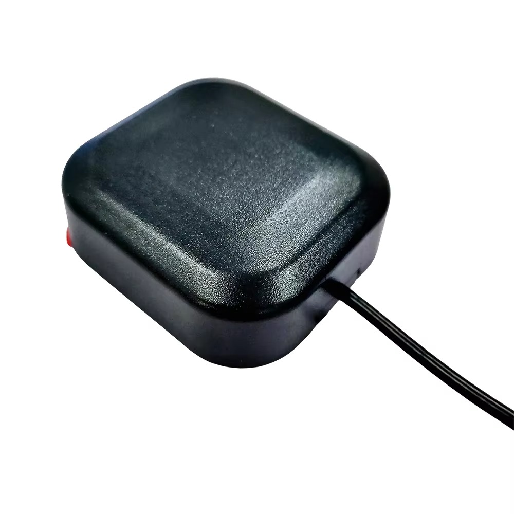
The internal components are housed in a radome—a protective cover that must be radio-transparent at the target frequencies.
Radome: Typically made from high-grade plastics like polycarbonate or ABS, the radome is designed to have minimal effect on the RF signals. Its shape is often aerodynamic for use on vehicles and includes features for mounting.
Durability: The entire assembly is potted with a dielectric compound to protect the delicate electronics from moisture, dust, shock, and vibration. The housing is rated to IP67 or higher, making it waterproof and dustproof for harsh outdoor and agricultural environments.
In summary, the construction of an RTK antenna is a careful balancing act. Engineers must optimize for wide bandwidth, stable phase characteristics, high gain, low noise, superior multipath rejection, and physical robustness. Every material and geometric choice has a direct consequence on the fidelity of the data passed to the receiver, making it the foundational sensor upon which all high-precision GNSS is built.
The operation of a multi-frequency dual-band RTK antenna is the first step in a complex chain of signal processing that culminates in a position fix of astonishing accuracy. Its working principle can be broken down into a sequence of key functions: reception, amplification, filtering, and delivery, all while maintaining the integrity of the signal's most precious attribute—its phase.
1. Signal Reception and Conversion:
The process begins when electromagnetic waves from GNSS satellites, traveling at the speed of light, impinge upon the antenna's radiating patch elements. These waves induce tiny, oscillating electrical currents on the patches. The geometry of the stacked patches ensures that this conversion happens efficiently for each target frequency band (L1, L2, L5) simultaneously. The antenna's right-hand circular polarization (RHCP) is crucial here, as it is matched to the polarization of the signals transmitted by the satellites, providing inherent rejection of many reflected signals (which often become left-hand polarized) and other interference.
2. Low-Noise Amplification:
The induced currents represent extremely weak signals, often buried in the thermal noise floor of electronics. They are immediately fed into the Low Noise Amplifier (LNA). The LNA's primary role is to boost the amplitude of these signals by a factor of 300 to 1000 times (25-40 dB) without distorting them. The "Low-Noise" aspect is critical; a poor-quality amplifier would add significant noise, obscuring the weak GNSS signals and making them unusable for precise carrier-phase tracking. This amplified signal is now strong enough to be sent down a cable to the receiver without being degraded by cable loss and external noise.
3. Bandpass Filtering and Delivery:
Following amplification, the signal passes through bandpass filters. These filters are tuned to the specific GNSS frequency bands (e.g., a passband from 1550-1610 MHz to cover L1 and Galileo E1, and another from 1160-1300 MHz to cover L2, L5, and others). Their job is to reject powerful out-of-band signals from sources like FM radio, VHF, UHF, and cellular networks (e.g., 4G/5G), which could otherwise overload the receiver's front-end.
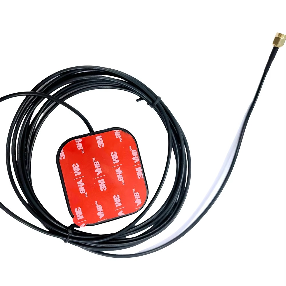
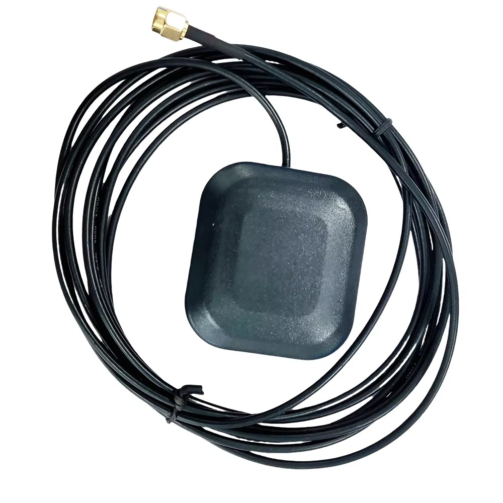
The conditioned, amplified, and filtered signals are then delivered via a coaxial cable (e.g., LMR®-400) to the RTK receiver. The antenna is often powered through this same cable using a DC voltage supplied by the receiver (phantom power), simplifying the system setup.
The Critical Role in Carrier-Phase Tracking:
While the antenna handles the analog domain, its performance is the sole determinant of the quality of data the receiver has to work with in the digital domain. The receiver's primary task for RTK is to track the phase of the carrier wave itself. The wavelength of the L1 carrier is approximately 19 cm. By measuring the phase to within 1% of a cycle, theoretical accuracy in the millimeter range is possible.
However, this phase measurement is incredibly delicate. Any distortion, phase shift, or instability introduced by the antenna corrupts this measurement. This is why the antenna's Phase Center Stability is paramount. If the electrical point from which the phase is measured moves—even by a millimeter—due to the angle of the incoming signal, the receiver will attribute this movement to a change in the satellite-to-antenna range, introducing a positioning error. The sophisticated design of the patch elements and ground plane is entirely focused on minimizing this variation.
The Multi-Frequency Advantage Enabled by the Antenna:
The antenna's ability to provide clean signals from multiple frequencies is what unlocks the most powerful error-correction techniques inside the receiver:
Ionospheric Delay Calculation: The ionosphere delays GNSS signals, an error that varies with time and location. Crucially, this delay is dispersive—it affects different frequencies by different amounts. By simultaneously measuring the precise phase on both the L1 and L2 frequencies, the receiver can calculate the exact amount of ionospheric delay affecting the signals and remove it almost entirely. This is the single largest contributor to error elimination in dual-frequency RTK.
Integer Ambiguity Resolution (IAR): The "integer ambiguity" is the unknown whole number of wavelengths between the satellite and receiver. Resolving this integer quickly and reliably is the key to RTK. Using multiple frequencies provides longer combined wavelengths (called wide-lane and narrow-lane combinations) that make the resolution process faster and more robust, especially in challenging environments with satellite obstructions. A triple-frequency antenna (L1/L2/L5) makes this process even faster and more reliable.
In essence, the antenna acts as a high-fidelity translator. It captures the faint, analog whispers from multiple satellites across multiple frequency bands, amplifies them without adding noise, strips away unwanted interference, and delivers a clean, stable set of signals to the receiver. The receiver then performs the digital wizardry of correlation, filtering, and computation, but it is entirely dependent on the quality of the raw material provided by the antenna. Without the antenna's stable phase reference and multi-band capability, the receiver's algorithms would be solving an unsolvable equation with noisy and biased data.
The adoption of multi-frequency dual-band RTK antennas brings a transformative set of advantages that enable applications previously thought impossible. However, this advanced capability does not come without its own set of significant challenges and trade-offs, both in terms of technology and implementation.
Advantages:
Unprecedented Accuracy and Precision: The primary advantage is the ability to achieve consistent centimeter-level (2-3 cm) horizontal and vertical accuracy in real-time. This is a quantum leap from the meter-level accuracy of single-frequency systems and is the enabling factor for automation and high-precision measurement.
Rapid Convergence and Reliability: Dual and triple-frequency signals drastically reduce the time required to resolve the integer ambiguity—the process known as initialization. Systems can achieve a fixed RTK solution in seconds rather than minutes. Furthermore, once fixed, they are far more robust and can maintain a "fix" even in moderately challenging environments like areas with light tree cover or near buildings, where single-frequency systems would frequently drop back to a less accurate "float" solution.
Effective Ionospheric Error Mitigation: As detailed previously, this is the killer feature. By measuring the differential delay between two frequencies, the system can mathematically eliminate the single largest source of signal error. This is especially critical over long baselines (the distance between the base and rover station) where the ionospheric conditions at each receiver might differ. Dual-frequency systems can operate effectively over baselines of tens of kilometers, whereas single-frequency RTK is typically limited to under 10-15 km.
Enhanced Multipath Rejection: The physical design of high-end RTK antennas, particularly those with choke rings, provides superior rejection of signals reflected from the ground, buildings, and other objects. Multipath error is notoriously difficult to correct in software, so mitigating it at the hardware level at the point of reception is immensely valuable. Furthermore, advanced receivers can use multi-frequency data to help identify and filter out residual multipath.
Future-Proofing and Constellation Flexibility: A multi-frequency antenna is inherently multi-constellation. It can receive signals from all modern GNSS systems (GPS, GLONASS, Galileo, BeiDou). This significantly increases the number of satellites available, improving accuracy, reliability, and availability in urban canyons or other obstructed areas. It also ensures the hardware remains viable as new signals from these constellations are activated and utilized.
Challenges and Considerations:
Cost and Complexity: This is the most significant barrier. The engineering, materials, and calibration required for a high-performance RTK antenna make it exponentially more expensive than a consumer-grade antenna. The entire system cost—including the antenna, dual-frequency RTK receiver, and software—is substantial, often placing it in the professional and industrial market segment.
Power Consumption: The active antenna requires power for its internal LNA. While typically not a huge drain (often 3-5V DC at 20-50mA), it is a consideration for battery-operated rover systems designed for long-duration fieldwork. The receiver must provide this clean, stable power over the coaxial cable.
Calibration and Measurement Bias: The problem of Phase Center Offset and Variation (PCO/PCV) turns the antenna from a simple sensor into a complex source of measurement bias. For applications demanding the highest geodetic accuracy, using an antenna without individually calibrated correction values can introduce systematic errors of several centimeters. This necessitates the additional step of obtaining and applying antenna model-specific calibration data (e.g., from the IGS or manufacturer), adding complexity to the data processing workflow.
Size and Weight: The requirement for a large ground plane and choke ring structure to achieve optimal multipath rejection results in antennas that are significantly larger, heavier, and less aerodynamic than their consumer counterparts. This can be a practical challenge for mounting on drones, small vehicles, or handheld equipment.
Interference and Jamming Vulnerability: While the antenna's filters reject out-of-band interference, the system remains vulnerable to in-band jamming and interference, whether accidental or intentional. The high gain of the LNA can actually make the system more susceptible to being overloaded by strong nearby RF sources. Sophisticated mitigation techniques are required at the receiver level to handle this.
System Integration: The antenna cannot work in isolation. Its performance is only realized when paired with a capable multi-frequency RTK receiver and sophisticated software. The entire data link for receiving correction data from the base station must also be robust and low-latency. This makes the entire system more complex to set up and manage compared to a standalone GPS receiver.
In conclusion, the advantages of multi-frequency dual-band RTK antennas are profound, directly enabling the precision required by modern technology. However, these advantages are traded for increased cost, complexity, and system-level considerations. The decision to use such a system is a calculated one, where the requirement for centimeter-level accuracy in real-time justifies the investment and expertise needed to overcome these challenges.
The unique capabilities of multi-frequency dual-band RTK technology have catapulted it from a niche geodetic tool into a cornerstone of modern automation and data-driven industries. Its applications are vast and growing, continually finding new use cases where extreme precision is not just beneficial but essential.
Current Applications:
Precision Agriculture: This is one of the largest and most mature markets. RTK guidance enables tractors and implements to follow sub-inch repeatable paths across fields. This allows for:
Autosteer: Reducing driver fatigue and enabling operation in low-visibility conditions (e.g., dust, fog, night).
Yield Mapping: Precisely correlating GPS location with yield data from monitors.
Variable Rate Application (VRA): Applying seed, fertilizer, and chemicals only where needed, at variable rates, dramatically reducing input costs and environmental impact.
Field Mapping: Accurately mapping field boundaries, problem areas, and drainage patterns.
Surveying, Mapping, and Geodesy: The traditional domain of RTK. Surveyors use it for high-accuracy mapping, construction layout, topographic surveys, and establishing control points. Its speed and accuracy have revolutionized the field, replacing slower, less accurate methods.
Construction and Machine Control: RTK antennas are mounted on bulldozers, graders, excavators, and pile drivers. The system guides the machine's blade or bucket to the exact design grade (e.g., a digital terrain model), eliminating the need for surveyor stakes and constantly checking grade. This increases speed, reduces rework, and saves significant material costs.
Unmanned Aerial Vehicles (Drones) and Aerial Mapping: Drones equipped with RTK (and its sibling, PPK – Post-Processed Kinematic) no longer rely solely on inferior GPS and image processing for geotagging. The RTK antenna provides centimeter-level accurate position for each captured image, enabling the creation of highly accurate orthomosaics, 3D models, and digital surface models without the need for numerous ground control points. This is crucial for volume calculations, stockpile monitoring, and infrastructure inspection.
Autonomous Vehicles and Robotics: While still evolving, RTK is a critical sensor in the sensor fusion suite for autonomous vehicles (cars, trucks, rovers) and mobile robots (in warehouses, farms, and mines). It provides an absolute, drift-free global position that complements other sensors like LiDAR, radar, and cameras. It is essential for lane-level navigation and precise docking.
Scientific Research and Monitoring: Used for monitoring tectonic plate movements, glacial flow, volcanic deformation, and landslide stability. The extreme precision allows scientists to measure movements of a few millimeters per year.
Future Trends:
Miniaturization and Integration: The relentless push is towards making these antennas smaller, lighter, lower power, and cheaper without sacrificing performance. This involves advanced materials, innovative designs like embedded antenna elements, and System-on-Chip (SoC) solutions that integrate the LNA and filtering more efficiently. This will open up new applications in wearables and consumer electronics.
Tightly-Coupled INS Integration: The future lies in deeply integrating RTK with Inertial Navigation Systems (INS). INS provides extremely smooth, high-frequency position, velocity, and attitude data but drifts over time. RTK provides a long-term accurate position that corrects the INS drift. When tightly coupled, the systems work together to provide continuous, robust, and accurate navigation even during complete GNSS outages (e.g., in tunnels, under heavy canopy, or in urban canyons). The antenna is a critical part of this integrated system.
Advanced Multi-Constellation, Multi-Frequency Support: As Galileo and BeiDou reach full operational capability and modernize their signals, future antennas will be designed to receive even more signals (e.g., L6, new civil signals on L2). This will further increase robustness, speed of initialization, and accuracy.
Network RTK and PPP-RTK: The reliance on a single base station is giving way to corrections delivered from a network of permanent reference stations (CORS networks) via the internet or satellite link. A related advanced technique is Precise Point Positioning with RTK (PPP-RTK), which promises global centimeter-level accuracy without a local base station. Antennas will need to be optimized to work seamlessly with these correction services.
Enhanced Resilience to Interference and Spoofing: As society becomes more dependent on GNSS, protecting it becomes paramount. Future antenna designs will incorporate advanced techniques like controlled reception pattern antennas (CRPAs) or array processing to actively nullify jamming and spoofing signals, making autonomous systems far more secure and reliable.
AI and Machine Learning for Performance Optimization: AI algorithms will be used to better model and predict antenna behaviors (like PCV) and to intelligently filter multipath and interference in real-time based on the antenna's environment, further pushing the boundaries of achievable accuracy.
The multi-frequency dual-band RTK antenna, therefore, is not a static technology. It is a rapidly evolving platform that is central to the ongoing navigation revolution, enabling machines to see their position in the world with ever-greater clarity and reliability.
Conclusion
The journey from the simple reception of satellite signals to the achievement of real-time, centimeter-level positioning is a remarkable feat of engineering. At the very beginning of this intricate data chain stands the multi-frequency dual-band RTK GPS antenna, a component whose sophistication and performance are the fundamental enablers of this precision. It is far more than a passive piece of hardware; it is a highly engineered system that acts as the critical gateway between the analog world of RF signals from space and the digital world of high-stakes positioning algorithms.
This series has detailed the antenna's multifaceted role: its Overview as the pinnacle of navigation technology; its complex Design and Construction focused on phase stability and signal fidelity; its Working Principles that transform faint waves into actionable data; the clear Advantages in accuracy and reliability weighed against the Challenges of cost and complexity; and its transformative Applications across industries, driven by ongoing Future Trends.
The overarching conclusion is that the performance ceiling of any RTK system is determined by its antenna. A receiver, no matter how powerful its processor or advanced its algorithms, can only compute positions based on the quality of the raw phase measurements it receives. Any noise, instability, bias, or distortion introduced at the antenna stage propagates through the entire system, corrupting the final result. The antenna's stable phase center, its ability to reject multipath, its low-noise amplification, and its capacity to cleanly receive multiple frequencies are not mere features—they are the foundational prerequisites for resolving the integer ambiguity and achieving centimeter-level truth.
As we look to a future increasingly defined by autonomy—self-driving cars, precision robots, automated industrial sites, and smart cities—the demand for reliable, absolute positioning will only intensify. These systems cannot rely on relative sensors alone; they require a globally referenced, drift-free, and incredibly accurate understanding of their location. The multi-frequency dual-band RTK antenna, especially when fused with other technologies like INS, provides this essential truth data.
The evolution of this technology towards miniaturization, deeper integration, and enhanced resilience promises to further broaden its impact, moving it from large industrial equipment into smaller, more pervasive devices. The ongoing expansion of global satellite constellations will provide more data for these antennas to consume, driving even greater performance.
In essence, the multi-frequency dual-band RTK antenna is a testament to the fact that in the realm of high technology, first impressions matter. The first point of contact—the gateway—must be designed with utmost care. It is this unassuming, often dome-shaped device that quietly and reliably unlocks the full potential of global navigation satellite systems, transforming them from a general-purpose guidance tool into a precise instrument for measurement, automation, and innovation. It is, without exaggeration, the indispensable eye of the autonomous world.

 86 0755 2819 9597
Lucy Yang | lucy.y@toxutech.com
Nicole Li | nicole@toxutech.com
Dotty Zhao | sales04@toxutech.com
Global Business Director / Sales Team / Global Operations


 En
En Cn
Cn Korean
 Home >


