

-
Products -PCBA Manufacturing RF Connectors RF Cable Assemblys Embedded Antennas External Antennas Positioning Chips and Modules
RF Connectors

RF Cable Assemblys
Embedded Antennas
External Antennas
Positioning Chips and Modules


 Language


Language


The multi-frequency RTK choke ring GPS antenna represents a pinnacle of precision in satellite navigation technology, specifically engineered to support high-accuracy real-time kinematic (RTK) positioning systems. As the demand for centimeter-level and even millimeter-level geospatial accuracy grows across surveying, geodesy, structural monitoring, and scientific research, the role of advanced GNSS antennas has become increasingly critical. Unlike standard patch or helical antennas used in consumer-grade devices, the multi-frequency RTK choke ring antenna is designed to minimize multipath interference—a major source of error in precise positioning—while simultaneously supporting signals from multiple frequency bands and global navigation satellite systems (GNSS), including GPS, GLONASS, Galileo, BeiDou, and others.
A "choke ring" refers to a specialized ground plane structure surrounding the radiating element of the antenna. This structure consists of concentric conductive rings separated by gaps and connected to a central hub, forming a series of resonant cavities that suppress surface currents induced by reflected signals. By attenuating these unwanted reflections—especially those arriving at low elevation angles—the choke ring significantly reduces multipath errors, which can otherwise introduce decimeter-level inaccuracies in carrier-phase measurements essential for RTK applications. The term "multi-frequency" indicates the antenna’s capability to receive and process signals across multiple GNSS bands such as GPS L1 (1575.42 MHz), L2 (1227.60 MHz), L5 (1176.45 MHz), Galileo E1, E5a, E5b, and BeiDou B1, B2, B3. This broad spectral coverage enables ionospheric delay correction, faster ambiguity resolution, and improved signal redundancy, all of which are vital for achieving robust and reliable high-precision positioning.
These antennas are typically deployed in static or semi-static configurations as part of base stations, Continuously Operating Reference Stations (CORS), monitoring networks, and calibration sites where long-term stability and measurement integrity are paramount. They serve as the primary interface between space-based satellite signals and ground-based receivers, ensuring that the incoming electromagnetic waves are captured with minimal distortion, phase center variation, and polarization mismatch. The phase center—the effective point from which the antenna measures distance to satellites—must be stable and well-characterized to avoid introducing systematic biases into positioning solutions. Multi-frequency choke ring antennas are designed with precisely controlled radiation patterns and symmetric phase center behavior across azimuth and elevation, making them ideal for scientific and metrological applications.
In addition to their use in traditional land surveying and geodetic networks, these antennas are increasingly employed in emerging fields such as crustal deformation monitoring, volcano and earthquake studies, dam and bridge health assessment, and satellite orbit determination. Their ability to maintain consistent performance under varying environmental conditions—including temperature fluctuations, humidity, and nearby metallic structures—ensures data continuity over extended periods. Moreover, with the proliferation of regional augmentation systems and network RTK services, choke ring antennas form the backbone of national and international reference frames, contributing to global standards like the International Terrestrial Reference Frame (ITRF).
Modern multi-frequency RTK choke ring antennas also incorporate features such as integrated radio frequency interference (RFI) filtering, lightning protection, and ruggedized enclosures to withstand outdoor deployment in harsh climates. Many models include built-in temperature sensors and self-calibration capabilities to monitor performance drift and support post-processing corrections. The mechanical design emphasizes symmetry and electromagnetic isolation, often featuring non-conductive radomes and corrosion-resistant materials to preserve signal integrity over years of continuous operation.
As GNSS constellations expand and signal architectures evolve—such as the introduction of modernized civil signals on L5 and E6—the need for future-proof antenna systems capable of handling higher data rates, wider bandwidths, and enhanced modulation schemes becomes more pressing. Next-generation choke ring antennas are being developed with ultra-wideband elements and adaptive filtering to accommodate these changes while maintaining their core function: delivering clean, stable, and highly accurate signal reception for the most demanding positioning applications.
In summary, the multi-frequency RTK choke ring GPS antenna is not merely a passive component but an active enabler of high-fidelity geospatial data acquisition. Its sophisticated electromagnetic design, combined with rigorous calibration and environmental resilience, makes it indispensable for any application where precision, reliability, and long-term consistency are non-negotiable. As the foundation of high-accuracy GNSS infrastructure, this antenna type continues to play a foundational role in advancing our understanding of Earth's dynamics and enabling next-generation spatial technologies.
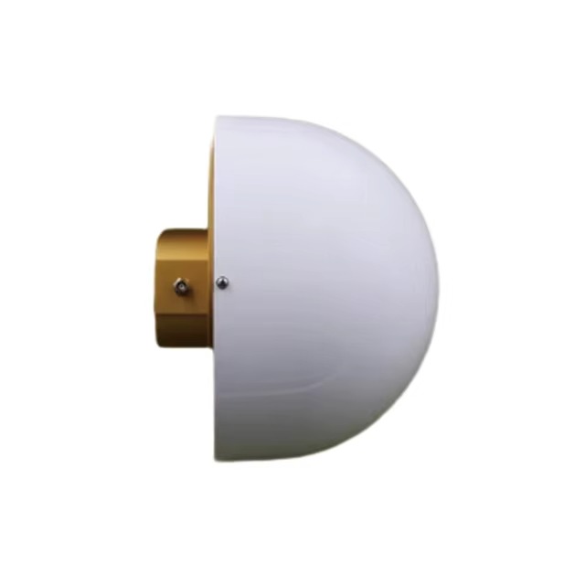
The design and construction of a multi-frequency RTK choke ring GPS antenna involve a meticulous integration of electromagnetic theory, microwave engineering, mechanical precision, and materials science to achieve optimal signal fidelity and multipath rejection. At its core, the antenna consists of three main components: the radiating element, the choke ring ground plane, and the housing/radome, each engineered to perform specific functions that collectively ensure high-performance GNSS signal reception.
The radiating element is typically a stacked patch antenna or a cavity-backed spiral design, chosen for its ability to operate efficiently across multiple frequency bands. A stacked configuration uses two or more dielectric layers with separate radiating patches tuned to different frequencies (e.g., one layer for L1/E1/B1 and another for L2/L5/E5/B2). This allows simultaneous reception of signals from GPS, Galileo, GLONASS, and BeiDou without significant cross-coupling or degradation in gain. The patch elements are usually made from copper or gold-plated metal etched onto low-loss, high-dielectric-constant substrates such as Rogers RO4003 or Teflon-based composites, which provide excellent RF performance and thermal stability.
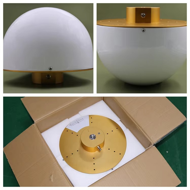
Surrounding the radiating element is the defining feature of the antenna: the choke ring structure. This consists of multiple concentric circular grooves machined into a conductive base (often aluminum or brass), forming a series of quarter-wavelength resonant cavities. Each groove acts as a parallel LC circuit that presents a very high impedance to surface waves propagating along the ground plane, effectively suppressing currents induced by reflected signals arriving at low elevation angles (< 10°–15°). The depth and width of the grooves are precisely calculated based on the lowest operating frequency (typically L2 or L5) to ensure resonance at the desired band. Advanced designs may use tapered or stepped-depth rings to broaden the suppression bandwidth and enhance performance across all GNSS frequencies.
To further improve multipath rejection, some high-end models incorporate absorptive materials within the choke walls or use hybrid choke-absorber configurations. These materials dissipate rather than reflect stray electromagnetic energy, reducing secondary scattering. Additionally, the top surface of the choke ring is often coated with a thin resistive layer or loaded with ferrite tiles to dampen residual surface waves.
The entire assembly sits atop a low-noise preamplifier (LNA) housed in a shielded compartment beneath the ground plane. The LNA boosts weak satellite signals immediately after reception to overcome cable losses and maintain a high signal-to-noise ratio (SNR). It is carefully matched to the antenna impedance (typically 50 Ω) and includes filtering stages to reject out-of-band interference from cellular networks, Wi-Fi, radar, and other RF sources. Modern LNAs are powered via bias voltage supplied through the coaxial cable (phantom power), eliminating the need for separate power lines.
Electromagnetic symmetry is paramount in the design. The antenna must exhibit uniform gain and phase response across all azimuth directions and stable phase center variation (PCV) with elevation angle. To achieve this, the choke ring is manufactured with tight tolerances using CNC machining or precision molding techniques. Any asymmetry—such as uneven groove depths or misaligned feed points—can distort the radiation pattern and introduce directional biases into carrier-phase measurements, compromising RTK accuracy.
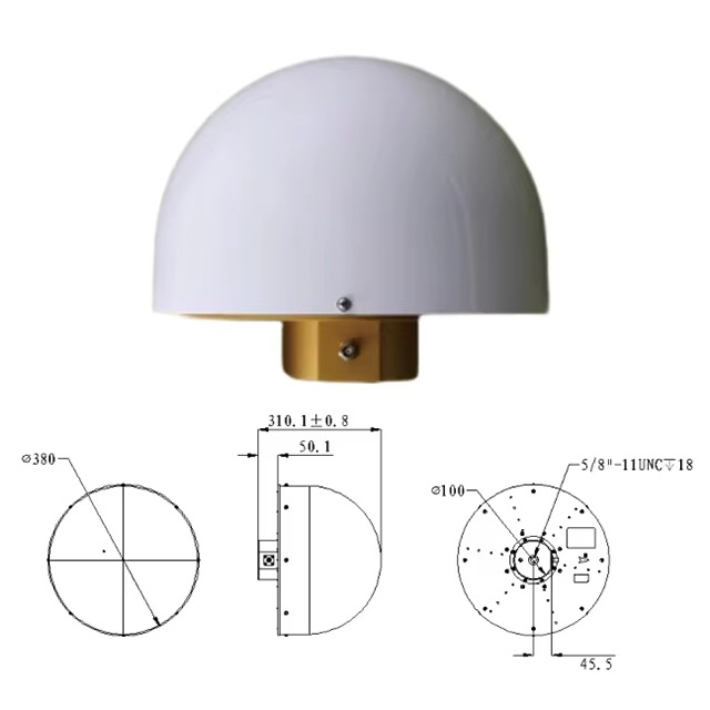
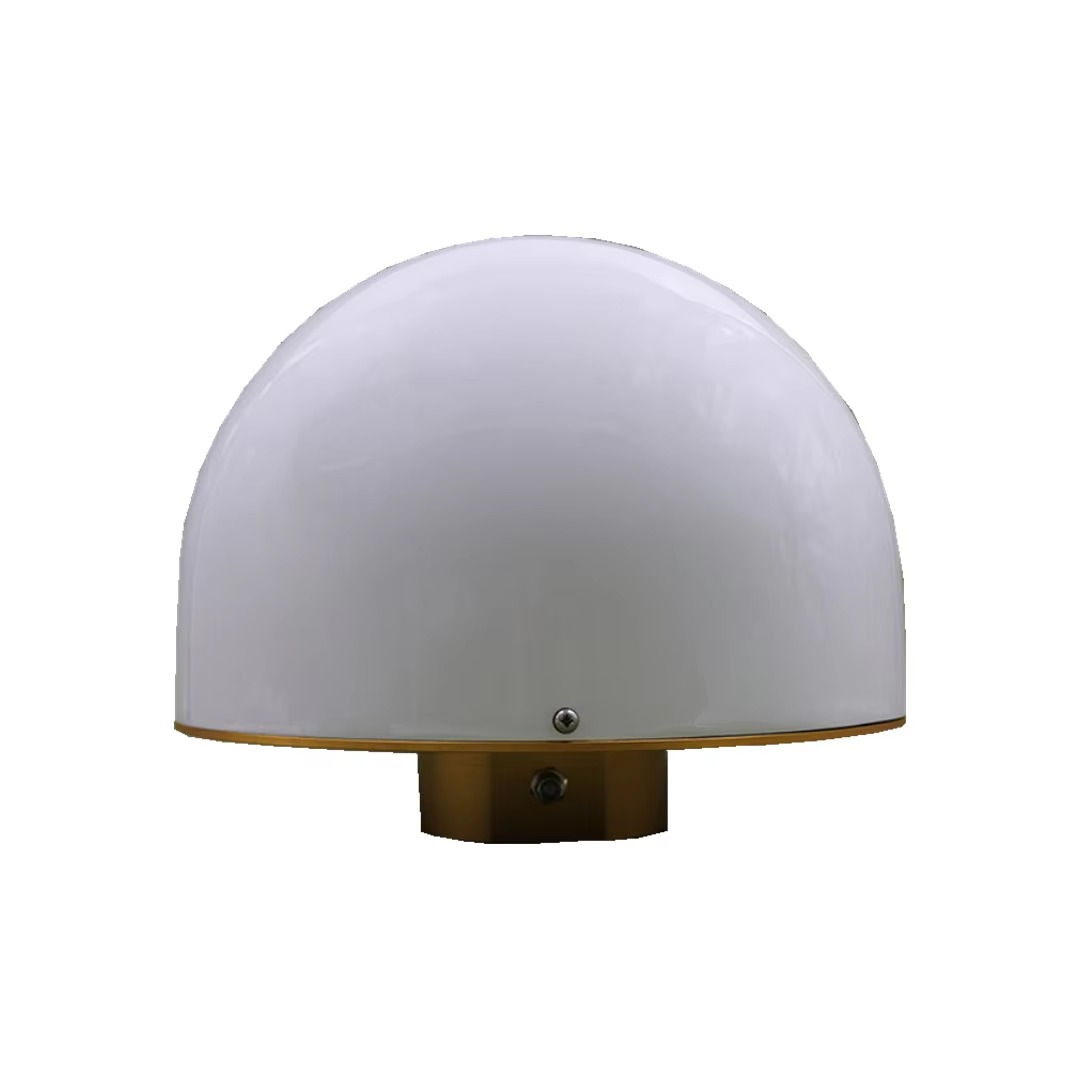
Mechanically, the antenna is enclosed in a weatherproof radome made from UV-stable polycarbonate or fiberglass-reinforced polymer. The radome protects internal components from moisture, dust, ice, and solar loading while remaining transparent to GNSS signals. Ventilation ports with hydrophobic membranes prevent condensation buildup without allowing water ingress. The base includes mounting provisions such as a tribrach adapter or threaded stud compatible with survey tripods and permanent monuments.
Thermal management is another critical aspect. Temperature gradients across the antenna can cause differential expansion of materials, leading to phase center drift. High-quality choke ring antennas use materials with matched coefficients of thermal expansion (CTE) and incorporate thermal shielding or insulating layers to minimize thermal gradients. Some models include embedded temperature sensors for real-time monitoring and correction in post-processing software.
Connectivity is provided via a low-loss coaxial cable (e.g., LMR-400 or equivalent) terminated with a weather-sealed connector such as TNC or N-type. Lightning and electrostatic discharge (ESD) protection circuits are integrated at the feed point to safeguard downstream equipment. Grounding kits are often included to ensure proper earthing, especially in lightning-prone areas.
Calibration is a final but essential step in construction. Each antenna undergoes rigorous anechoic chamber testing to characterize its phase center offset (PCO) and phase center variation (PCV) for each frequency and direction. These values are documented in antenna calibration files (e.g., ANTEX format) used by GNSS processing software to correct measurement biases, ensuring compatibility with international standards like IGS (International GNSS Service).
In summary, the design and construction of a multi-frequency RTK choke ring GPS antenna represent a convergence of precision engineering and electromagnetic optimization. Every component—from the multi-layer patch radiator to the resonant choke structure—is meticulously crafted to deliver exceptional signal purity, multipath immunity, and long-term stability, making it the gold standard for high-accuracy GNSS applications.
The working principles of a multi-frequency RTK choke ring GPS antenna revolve around the precise capture and conditioning of satellite signals to enable high-accuracy real-time kinematic (RTK) positioning. At its core, this antenna functions as a highly selective electromagnetic interface between space-based GNSS transmitters and ground-based receivers, ensuring that the received signals are clean, stable, and minimally distorted—critical prerequisites for carrier-phase-based measurements.
The fundamental operation begins with signal reception. GNSS satellites transmit right-hand circularly polarized (RHCP) signals across multiple frequency bands. The radiating element—typically a stacked patch or spiral design—captures these signals through electromagnetic induction. Each layer of the stacked patch is tuned to resonate at specific frequencies (e.g., L1, L2, L5), allowing simultaneous reception of signals from GPS, Galileo, GLONASS, and BeiDou constellations. The circular polarization of the incoming waves matches the antenna's polarization response, maximizing signal capture while rejecting left-hand polarized reflections, which are common in multipath environments.
Once captured, the weak microwave signals (on the order of -130 dBm to -160 dBm) are immediately amplified by a low-noise amplifier (LNA) located directly beneath the radiating element. This proximity is crucial to prevent degradation of the signal-to-noise ratio (SNR) due to cable losses. The LNA boosts the signal strength while adding minimal internal noise, preserving the integrity of the carrier phase—a key observable in RTK processing. After amplification, the signal passes through bandpass filters that reject out-of-band interference from sources such as 4G/5G cellular networks, radio transmitters, and radar systems, which could otherwise desensitize the receiver or introduce measurement errors.
A defining feature of the choke ring antenna is its ability to suppress multipath interference, which occurs when satellite signals reflect off nearby surfaces (e.g., buildings, vehicles, water, or the ground) before reaching the antenna. These reflected signals travel a longer path than the direct line-of-sight signal, causing phase delays that corrupt carrier-phase measurements and degrade positioning accuracy. The choke ring structure mitigates this by creating a high-impedance barrier to surface waves propagating along the ground plane. The concentric grooves act as resonant cavities tuned to a quarter-wavelength of the lowest operating frequency, effectively reflecting incoming surface currents back toward their source and canceling them out. This results in a sharp null in the antenna’s radiation pattern at low elevation angles (< 10°), where most ground reflections originate.
Additionally, the symmetrical design of the choke ring ensures uniform gain and phase response across all azimuth directions, minimizing directional biases. The phase center—the effective electrical point from which distance to satellites is measured—is engineered to be as stable as possible across elevation and frequency. However, slight variations do occur due to manufacturing tolerances and environmental factors. To account for this, each antenna undergoes rigorous calibration in anechoic chambers to determine its Phase Center Offset (PCO) and Phase Center Variation (PCV), which are then applied during post-processing using standardized correction models (e.g., IGS ANTEX files).
In multi-frequency operation, the antenna supports concurrent reception on L1, L2, L5, E1, E5a/b, B1, B2, etc. This enables advanced signal processing techniques such as ionospheric delay correction. The ionosphere, a layer of charged particles in the upper atmosphere, slows down GNSS signals in a frequency-dependent manner. By comparing the phase difference between two frequencies (e.g., L1 and L2), the total electron content (TEC) along the signal path can be estimated and removed, significantly improving positioning accuracy. Multi-frequency capability also enhances ambiguity resolution in RTK, allowing faster convergence and more reliable integer fixing of carrier-phase cycles.
When integrated into an RTK system, the antenna feeds corrected signals to a dual-frequency GNSS receiver, which computes position using both code (pseudorange) and carrier-phase measurements. The base station equipped with the choke ring antenna broadcasts differential corrections to a rover unit via radio or cellular link. Because the base antenna provides exceptionally clean and stable measurements, the resulting corrections are highly accurate, enabling the rover to achieve centimeter-level precision in real time.
Moreover, the antenna’s wide bandwidth and low phase distortion characteristics support modernized GNSS signals with complex modulations (e.g., BOC, MBOC), ensuring compatibility with current and future satellite transmissions. Its performance remains consistent under varying thermal conditions due to materials selected for matched thermal expansion coefficients, minimizing phase center drift over temperature cycles.
In essence, the working principle of the multi-frequency RTK choke ring GPS antenna is not merely about receiving signals, but about doing so with unparalleled fidelity. By combining multipath suppression, multi-band reception, phase stability, and electromagnetic symmetry, it creates the ideal input environment for high-precision GNSS processing, forming the foundation upon which RTK and PPP (Precise Point Positioning) solutions are built.
The multi-frequency RTK choke ring GPS antenna offers numerous advantages that make it the preferred choice for high-precision geospatial applications, yet it also presents certain challenges related to cost, deployment, and environmental sensitivity.
One of the primary advantages is exceptional multipath rejection. The choke ring structure effectively eliminates low-elevation reflected signals, reducing one of the largest sources of error in carrier-phase measurements. This leads to improved measurement consistency, faster ambiguity resolution, and higher positioning accuracy—often within 1–2 cm horizontally and 2–3 cm vertically under optimal conditions. In scientific and surveying applications where data integrity is paramount, this level of reliability is indispensable.
Another major benefit is multi-frequency and multi-constellation support. By receiving signals across L1, L2, L5, and other bands from GPS, Galileo, GLONASS, and BeiDou, the antenna enables robust ionospheric correction, increased satellite availability, and redundancy in obstructed environments. This improves solution availability, especially in urban canyons or forested areas, and allows for faster initialization times in RTK mode.
The stable and well-characterized phase center is another critical advantage. Unlike simple patch antennas whose phase centers shift significantly with elevation and azimuth, choke ring antennas exhibit minimal phase center variation (PCV). Combined with factory calibration data (ANTEX files), this allows precise modeling of measurement biases, ensuring compatibility with international reference frames like ITRF and WGS84. This makes them ideal for CORS networks, crustal deformation monitoring, and satellite orbit determination.
Additionally, these antennas offer long-term stability and durability. Constructed from corrosion-resistant materials and housed in rugged radomes, they are designed for continuous outdoor operation in extreme climates—from arctic cold to tropical humidity. Their mechanical and electrical properties remain consistent over years, making them suitable for permanent installations in geodetic monitoring networks.
However, several challenges must be considered. First is cost. Due to their complex design, precision manufacturing, and calibration requirements, multi-frequency choke ring antennas are significantly more expensive than standard GNSS antennas—often costing thousands of dollars per unit. This limits their use to high-end applications where return on investment justifies the expense.
Second, size and weight can be prohibitive for mobile or UAV-based deployments. The large diameter (typically 20–40 cm) and heavy construction make them unsuitable for integration into compact or lightweight platforms. They are primarily used in static base stations rather than rovers or drones.
Third, installation sensitivity is a concern. Proper leveling, grounding, and siting are essential to maintain performance. Nearby metallic objects, fences, or buildings can disrupt the choke ring’s electromagnetic symmetry and degrade multipath suppression. Ideal placement requires a clear sky view and isolation from reflective surfaces, which may not always be feasible in urban environments.
Furthermore, while the antenna itself is highly accurate, its performance depends on the quality of the connected receiver, cabling, and environmental conditions. Poor-quality coaxial cables or inadequate lightning protection can introduce noise or damage the system. Temperature gradients across the antenna body can still cause minor phase center drift, requiring thermal compensation in ultra-high-precision applications.
Lastly, emerging threats from RF interference pose a growing challenge. With increasing congestion in the L-band spectrum from terrestrial transmitters and potential jamming/spoofing attacks, even the best choke ring antennas require additional filtering and monitoring to maintain signal integrity.
Despite these challenges, the advantages far outweigh the limitations in professional and scientific contexts. Ongoing advancements in miniaturization, adaptive filtering, and hybrid choke-absorber designs are helping to mitigate some drawbacks, ensuring that these antennas remain at the forefront of high-precision GNSS technology.
The multi-frequency RTK choke ring GPS antenna is a cornerstone technology in numerous high-precision applications where centimeter- to millimeter-level positioning accuracy, long-term stability, and measurement integrity are non-negotiable. Its primary use lies in geodetic surveying and national mapping, where it serves as the reference point for cadastral surveys, boundary determinations, and topographic mapping. By forming part of Continuously Operating Reference Stations (CORS), these antennas provide real-time correction data to roving GNSS units, enabling rapid and accurate field measurements across large geographic areas.
In crustal deformation monitoring, choke ring antennas are deployed in dense networks to detect subtle movements of tectonic plates, fault lines, and volcanic regions. For example, in earthquake-prone zones like California or Japan, arrays of these antennas continuously record ground displacement with sub-centimeter precision, offering early warning indicators and improving seismic hazard models. Similarly, in volcano monitoring, such as at Mount Etna or Kīlauea, sustained deformation patterns captured by choke ring-equipped stations help predict eruptions by revealing magma migration beneath the surface.
Another critical application is infrastructure health monitoring. Bridges, dams, tall buildings, and tunnels are instrumented with high-precision GNSS receivers connected to choke ring antennas to track structural displacements over time. For instance, the Millau Viaduct in France and the Three Gorges Dam in China utilize such systems to monitor settlement, thermal expansion, and wind-induced sway. The ability to detect slow creep or sudden shifts enables proactive maintenance and enhances public safety.
In scientific research, these antennas contribute to studies in glaciology, subsidence, and sea-level rise. In polar regions, they are installed on ice sheets to measure glacial flow rates and grounding line retreat. In coastal zones, they support vertical land motion (VLM) measurements, which are essential for distinguishing between actual sea-level rise and local subsidence—key inputs for climate modeling and coastal planning.
The aerospace and satellite navigation sectors also rely on choke ring antennas for satellite orbit determination and clock synchronization. Ground tracking stations equipped with these antennas form part of global networks like the International GNSS Service (IGS), providing precise ranging data used to compute satellite ephemerides and clock corrections. These data feed into real-time augmentation services (e.g., SBAS, PPP-RTK) that enhance positioning accuracy worldwide.
Moreover, choke ring antennas play a role in calibration and metrology. National geodetic agencies use them as reference standards to calibrate other GNSS equipment, validate new signal processing algorithms, and maintain national coordinate systems. Their stable phase centers and well-documented error characteristics make them ideal for traceable, repeatable measurements.
Looking ahead, several future trends are shaping the evolution of multi-frequency RTK choke ring antennas. One major direction is miniaturization without performance loss. Advances in metamaterials and electromagnetic bandgap (EBG) structures may allow smaller choke-like effects in compact form factors, making them suitable for UAVs, mobile mapping systems, and urban sensor nodes.
Another trend is integration with multi-sensor fusion systems. Future antennas may embed inertial measurement units (IMUs), barometers, and environmental sensors to provide hybrid positioning solutions resilient to signal outages. This is particularly valuable in challenging environments where GNSS signals are intermittently blocked.
Adaptive filtering and cognitive radio techniques are being explored to combat increasing radio frequency interference (RFI). Smart antennas could dynamically adjust their reception patterns or notch out jamming signals in real time, preserving signal integrity in congested spectral environments.
With the rollout of new GNSS signals—such as GPS L1C, Galileo E6, and BeiDou B2b—the demand for ultra-wideband choke ring designs will grow. Antennas capable of covering 1100–1600 MHz seamlessly will ensure backward compatibility while supporting higher data rates, improved modulation schemes (e.g., AltBOC), and enhanced security features.
Furthermore, AI-driven diagnostics and self-calibration are emerging. Machine learning models could analyze received signal quality, temperature profiles, and multipath signatures to autonomously detect degradation, predict maintenance needs, or correct phase center drift in real time.
Finally, the rise of PPP-RTK (Precise Point Positioning with RTK corrections) and autonomous systems is driving demand for globally consistent, high-fidelity reference data. Choke ring antennas will remain central to this infrastructure, ensuring that next-generation autonomous vehicles, drones, and smart cities have access to reliable, high-accuracy positioning.
As GNSS becomes increasingly embedded in critical infrastructure and scientific discovery, the role of the multi-frequency RTK choke ring antenna will only expand—evolving from a passive receiver to an intelligent, adaptive node in a global network of precision sensing.
Conclusion
The multi-frequency RTK choke ring GPS antenna stands as a pinnacle of engineering achievement in the realm of high-precision satellite navigation. Its sophisticated design, rooted in electromagnetic theory and precision manufacturing, enables unparalleled signal fidelity, multipath rejection, and phase stability—qualities that are indispensable for applications demanding centimeter- or even millimeter-level accuracy. By integrating choke ring technology with multi-frequency and multi-constellation capabilities, this antenna effectively mitigates key sources of GNSS error, including ionospheric delay, low-elevation reflections, and phase center variation, thereby serving as the foundation for reliable real-time kinematic (RTK) and precise point positioning (PPP) solutions.
From its robust construction using resonant cavities and low-noise amplifiers to its symmetrical radiation pattern and calibrated phase center, every aspect of the antenna is optimized for metrological-grade performance. It plays a vital role in geodetic networks, crustal deformation monitoring, infrastructure health assessment, and scientific research, where long-term data consistency and environmental resilience are paramount. Its deployment in CORS stations and global tracking networks ensures that high-accuracy positioning is not just a local capability but a globally accessible service.
While challenges such as cost, size, and installation sensitivity limit its use in consumer or mobile platforms, ongoing advancements in materials science, miniaturization, and adaptive signal processing are paving the way for next-generation variants that retain performance while expanding applicability. The integration of AI, multi-sensor fusion, and cognitive radio functions promises to make these antennas smarter and more resilient in increasingly complex RF environments.
As society moves toward autonomous systems, smart infrastructure, and climate-resilient planning, the need for trustworthy spatial data has never been greater. The multi-frequency RTK choke ring GPS antenna, though often operating silently in the background, remains a critical enabler of this future—ensuring that the world's most demanding positioning tasks are performed with the highest degree of accuracy, reliability, and confidence. In essence, it is not merely an antenna, but a cornerstone of modern geospatial intelligence.

 86 0755 2819 9597
Lucy Yang | lucy.y@toxutech.com
Nicole Li | nicole@toxutech.com
Dotty Zhao | sales04@toxutech.com
Global Business Director / Sales Team / Global Operations


 En
En Cn
Cn Korean
 Home >


