

-
Products -PCBA Manufacturing RF Connectors RF Cable Assemblys Embedded Antennas External Antennas Positioning Chips and Modules
RF Connectors

RF Cable Assemblys
Embedded Antennas
External Antennas
Positioning Chips and Modules


 Language


Language


The Global Navigation Satellite System (GNSS) has evolved from a novel technology into a critical utility underpinning modern civilization. From enabling turn-by-turn navigation in vehicles to synchronizing global financial networks and guiding autonomous agricultural equipment, the demand for precise positioning, navigation, and timing (PNT) is insatiable. This escalating demand has driven a fundamental shift in satellite technology: the move from single-band (primarily GPS L1) to multi-band GNSS reception. A multi-band embedded GNSS antenna is the specialized front-end component designed to harness this new era of satellite signals, becoming the cornerstone of high-precision applications.
The Global Navigation Satellite System (GNSS) has evolved from a novel technology into a critical utility underpinning modern civilization. From enabling turn-by-turn navigation in vehicles to synchronizing global financial networks and guiding autonomous agricultural equipment, the demand for precise positioning, navigation, and timing (PNT) is insatiable. This escalating demand has driven a fundamental shift in satellite technology: the move from single-band (primarily GPS L1) to multi-band GNSS reception. A multi-band embedded GNSS antenna is the specialized front-end component designed to harness this new era of satellite signals, becoming the cornerstone of high-precision applications.
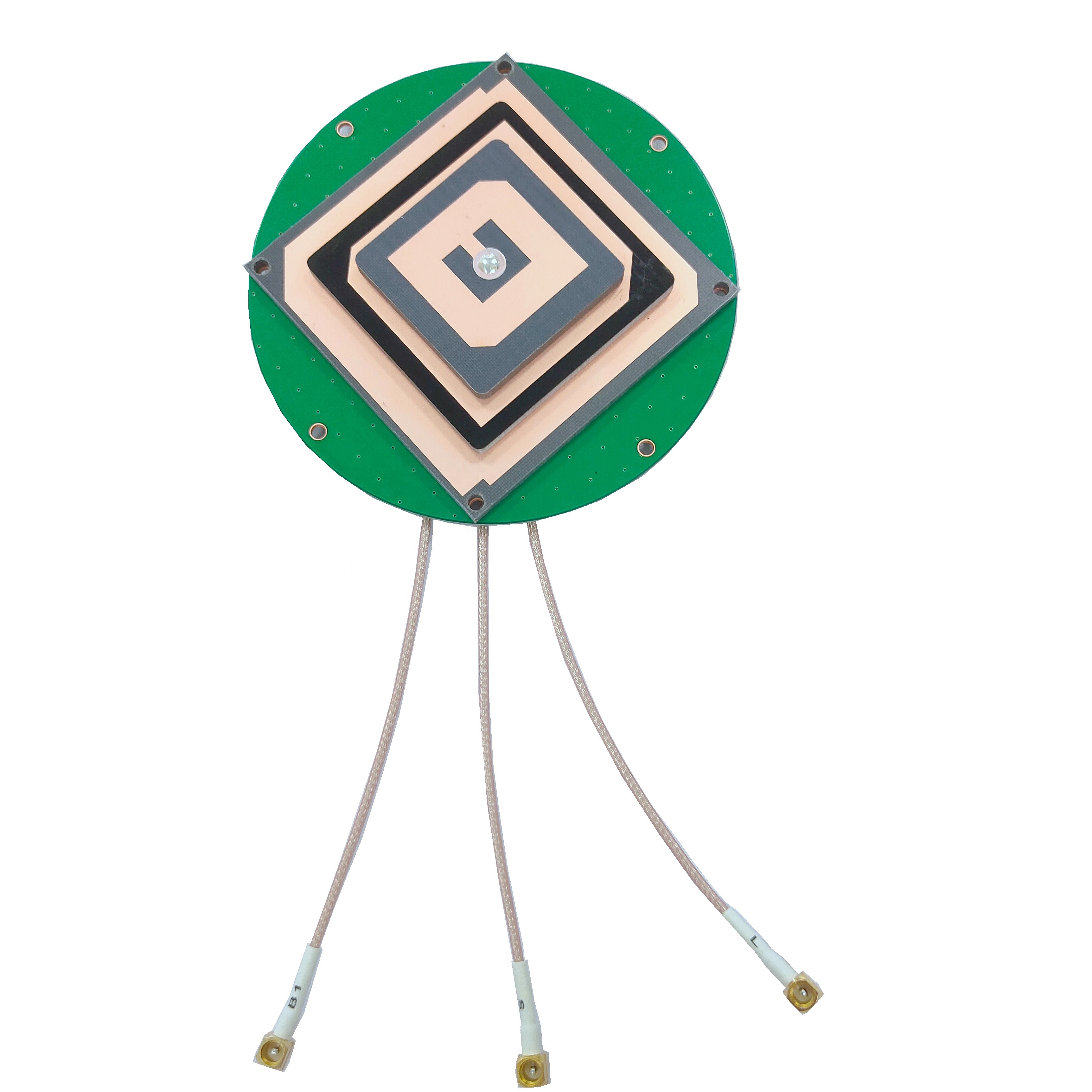
At its core, a multi-band GNSS antenna is designed to receive signals across multiple frequency bands transmitted by various satellite constellations. These include the American GPS (L1 C/A, L2C, L5), Russian GLONASS (L1, L2, L3), European Galileo (E1, E5a, E5b, E6), and Chinese BeiDou (B1, B2, B3). Unlike its single-band predecessor, which only accesses the coarse/acquisition (C/A) code on the L1 frequency (~1575.42 MHz), a multi-band antenna can simultaneously receive signals on two or more frequencies, such as L1 and L5.
This capability is not merely incremental; it is transformative. The primary advantage lies in mitigating the largest source of error in GNSS: signal delay caused by the Earth's ionosphere. The ionosphere is a layer of charged particles that slows down and bends RF signals. This delay is frequency-dependent. By measuring the difference in arrival time between two signals (e.g., L1 and L5) broadcast from the same satellite, a GNSS receiver can precisely calculate and eliminate almost all of the ionospheric error. This technique, known as ionospheric correction, is the key to moving from meter-level accuracy to decimeter or even centimeter-level accuracy.
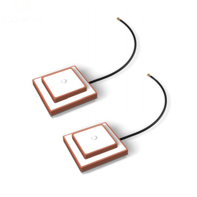
An embedded antenna is defined by its form factor and integration methodology. Unlike an external antenna with a standalone radome and connector, an embedded antenna is designed to be integrated directly onto the printed circuit board (PCB) of the host device or within its housing. This approach is essential for the miniaturization and aesthetic design of modern consumer and industrial electronics, including smartphones, drones, wearable devices, asset trackers, and advanced automotive telematics units.
The design of these antennas presents a profound engineering challenge. They must be:
Electrically Complex: Capable of operating efficiently across multiple, widely separated frequency bands (e.g., 1176 MHz for L5 and 1575 MHz for L1) with consistent performance.
Physically Compact: Often occupying a footprint of less than 25mm x 25mm and a height of just a few millimeters to fit within slim devices.
Environmentally Resilient: Performance must be stable despite proximity to other components, the device's own housing, and the user's hand (in the case of a phone).
Cost-Effective: Designed for high-volume manufacturing to meet the demands of consumer markets.
The shift to multi-band GNSS represents a new chapter in positioning technology. It enables Real-Time Kinematic (RTK) correction for surveying and agriculture, Precise Point Positioning (PPP) for autonomous vehicles, and faster, more robust location fixes in challenging urban environments. The multi-band embedded antenna is the critical gateway that makes this possible, acting as the sensitive ear that listens to a chorus of satellites across the spectrum, transforming their faint whispers into a precise and reliable geographical truth.
The creation of a high-performance multi-band embedded GNSS antenna is an exercise in overcoming conflicting requirements: wide bandwidth versus small size, efficiency versus isolation, and performance versus cost. Its construction is a sophisticated blend of materials science, electromagnetic theory, and precision manufacturing.
1. Antenna Element Technology:
The radiating element is the heart of the antenna. For multi-band embedded solutions, several technologies dominate:
Planar Inverted-F Antenna (PIFA): A very common choice for mobile devices. The PIFA is a resonant antenna where the element is grounded at one end and fed at another point along its length. Its primary advantage is its low profile, making it ideal for space-constrained applications. Designing a PIFA for multiple bands involves creating multiple resonant paths within a single element or carefully shaping the element to excite harmonics. Tuning is achieved by adjusting the length, width, and position of the feed and ground points.
Patch Antenna: A classic design consisting of a metal patch on a dielectric substrate over a ground plane. While traditionally thicker, modern ceramic patch antennas are a popular embedded solution. They use a high-dielectric-constant ceramic material (e.g., alumina) to shrink the wavelength within the substrate, allowing for a very compact form factor while maintaining good efficiency. Multi-band operation is achieved by incorporating multiple feed points or by etching sophisticated slot patterns into the patch to excite separate resonances.
Fractal Antennas: An advanced design where the radiating element is based on a fractal geometric pattern that repeats at different scales. This self-similar property is naturally suited to operating at multiple frequencies. Fractal antennas can be highly compact and exhibit good multi-band performance without the need for separate discrete elements.
2. The Critical Role of the Ground Plane:
In embedded antenna design, the PCB itself is not a passive host; it is an active part of the antenna system. For most embedded antennas, the PCB's copper layer acts as the essential ground plane. The antenna's performance, including its resonant frequency, bandwidth, and radiation pattern, is intensely coupled to the size, shape, and quality of this ground plane.
A larger ground plane typically supports better efficiency and a more stable pattern.
The antenna must be placed on a "keep-out" area of the PCB, meaning no other components or copper pours should be placed beneath or immediately around it, as they would detune it.
This dependency makes antenna design a system-level endeavor, requiring collaboration between the antenna specialist and the PCB layout engineer from the very beginning.
3. Advanced Materials:
Dielectric Substrates: The antenna element is often printed or placed on a specialized substrate. Materials like FR-4, Rogers RO4003C, or ceramic composites are chosen for their stable dielectric constant and low loss tangent, which are crucial for maintaining efficiency, especially at higher frequencies.
Magnetic Materials: Some designs incorporate materials with high magnetic permeability. These materials can help slow down the wave, effectively making the antenna electrically larger than its physical size, which is a key technique for miniaturization.
4. Feeding and Matching Networks:
Achieving a low Voltage Standing Wave Ratio (VSWR) across multiple bands is challenging. A simple antenna element will rarely have a perfect 50-ohm match at all desired frequencies. Therefore, an external matching network is almost always required.
This network, placed on the PCB between the antenna feed point and the GNSS receiver module, consists of tiny inductors (Ls) and capacitors (Cs).
This LC network acts as an impedance transformer, smoothing out the antenna's native impedance curve to present a consistent 50-ohm load to the receiver across all target bands. This maximizes power transfer and minimizes reflected energy.
5. Integration and Shielding:
3D Plastic Housing: The antenna's performance is dramatically affected by its proximity to the device's plastic housing. The dielectric properties of the plastic can shift the resonant frequencies. Modern design uses 3D electromagnetic simulation software to model the entire assembly—antenna, PCB, and housing—as a single system to predict and correct for these effects before a physical prototype is ever built.
Shielding: GNSS signals are extremely weak. To prevent de-sensing (interference) from nearby digital noise sources like processors, memory, and display drivers, the antenna and the GNSS receiver path are often shielded with metal cans or shielded flex circuits.
The construction of a multi-band embedded GNSS antenna is thus a holistic process. It is not the design of a standalone component but the co-design of an entire electromagnetic ecosystem within the device, where every adjacent material and structure becomes a variable in the complex equation of performance.
The operational principle of a multi-band embedded GNSS antenna transcends basic radiation and reception. It is about enabling advanced signal processing techniques that fundamentally redefine accuracy.
1. The Core Function: Resonant Reception:
At its most fundamental level, the antenna works on the principle of resonance. The physical dimensions of the antenna elements are carefully calculated to be a specific fraction of the wavelength of the target GNSS frequencies. For instance, a quarter-wavelength at L1 (1575 MHz) is approximately 47.6mm in free air, but this is reduced when printed on a dielectric substrate. When the RF electromagnetic wave from a satellite impinges on the antenna, it induces the strongest current and voltage standing wave at its resonant frequencies. A multi-band antenna is engineered to have multiple such resonances, allowing it to efficiently convert the L1, L2, and L5 signals into electrical currents that travel down the transmission line to the receiver.
2. The Radiation Pattern: A View of the Sky:
The ideal radiation pattern for a GNSS antenna is a wide, hemispherical dome. This "skyward" pattern ensures the antenna can receive signals from satellites at all elevations, from those directly overhead to those near the horizon. The embedded antenna's pattern is shaped by its design and its environment—specifically the device's ground plane and housing. A key metric is axial ratio, which measures the antenna's circular polarization purity. GNSS signals use Right-Hand Circular Polarization (RHCP) to mitigate signal degradation caused by reflections. A good antenna must maintain a low axial ratio (ideally < 3 dB) across its field of view to efficiently capture these signals and reject reflected, left-hand polarized multipath signals.
3. Enabling Ionospheric Correction: The Dual-Frequency Advantage:
This is the pivotal function. The ionosphere delays the code modulation (the digital PRN code) and advances the carrier phase of the signal. The magnitude of this delay is inversely proportional to the square of the frequency.
A single-band receiver must use a complex model to estimate this delay, which is the largest source of error, resulting in meter-level inaccuracy.
A dual-band receiver measures the difference in arrival time between the two signals (e.g., the P-code on L1 and the civil signal on L2, or the C/A code on L1 and the new L5 signal).
Because the ionospheric effect on each frequency is different and mathematically predictable, the receiver can solve for the exact delay and subtract it from the calculation. This eliminates ~90% of the ionospheric error, enabling decimeter-level accuracy with techniques like PPP and centimeter-level with RTK.
4. Multipath Rejection:
Multi-band signals, particularly the modern L5 and E5 signals, have wider bandwidths and more advanced codes. This inherent structure makes them more robust against multipath interference—signals that have bounced off buildings or the ground before reaching the antenna. The antenna itself aids in this by maintaining a good pattern that minimizes reception at low angles where multipath is most prevalent.
5. System Integration:
The antenna does not work in isolation. Its performance is part of a chain that includes:
Low-Noise Amplifier (LNA): An LNA is absolutely critical. It is placed as close to the antenna feed point as possible to amplify the extremely weak satellite signals (often below -130 dBm) before they are attenuated by the transmission line and contaminated by the noise figure of the receiver itself. Many embedded antenna solutions come with an integrated LNA.
Receiver Correlation: The receiver contains sophisticated algorithms and hardware correlators that acquire, track, and process the signals from each band, using the precise timing information provided by the antenna's captured waveforms to compute the final position.
In essence, the multi-band antenna provides the raw, high-fidelity data from multiple frequency domains that the receiver's algorithms need to perform their error-correcting magic. It is the foundation upon which all high-precision GNSS is built.
The adoption of multi-band embedded GNSS antennas offers transformative benefits but introduces significant design complexities that must be meticulously managed.
Advantages:
Unparalleled Accuracy: The principal advantage. Multi-band reception enables real-time ionospheric correction, elevating positioning accuracy from meter-level to decimeter or centimeter-level. This opens up entirely new application domains.
Enhanced Robustness and Reliability: Access to multiple constellations (GPS, Galileo, etc.) and multiple frequencies provides significant redundancy. If signals on one frequency are jammed, obscured, or degraded, the receiver can fall back on another. This leads to faster Time-To-First-Fix (TTFF) and more consistent performance in challenging urban canyons and under dense foliage.
Superior Multipath Mitigation: Modern satellite signals on L5/E5 are more resistant to multipath, and the receiver can use multi-band data to better identify and filter out these erroneous signals.
Miniaturization and Aesthetics: The embedded form factor allows for sleek, compact, and robust product designs without external protrusions, which is critical for consumer electronics like smartphones and wearables.
Future-Proofing: As new satellite signals become operational (e.g., Galileo's full operational capability), a multi-band antenna is already equipped to leverage them, protecting the investment in the device design.
Challenges:
Size vs. Performance Trade-off: This is the fundamental challenge. Physics dictates that antenna efficiency and bandwidth are proportional to size. Designing a single element that is both small and efficient across multiple, low-frequency bands (like L5 at 1176 MHz) is extremely difficult. Designers often must accept lower efficiency at the lower bands.
Complex Integration and Co-Design: The antenna's performance is inextricably linked to the device's PCB and mechanical design. A last-minute change to the housing plastic or the PCB layout can completely detune the antenna, requiring costly and time-consuming re-spins. This demands early and continuous collaboration between mechanical, PCB, and RF engineers.
Increased Bill of Materials (BOM) Cost: A multi-band antenna is more complex to design and manufacture than a single-band antenna. Furthermore, the system requires a multi-band GNSS receiver chipset, which is more expensive, and often an external LNA and a more complex matching network.
Power Consumption: While the antenna itself is passive, the system-level power draw may be higher due to the LNA and the increased processing power required to handle the additional data from multiple frequency bands.
Susceptibility to Environmental De-tuning: The proximity of the human body (the "hand effect" on a phone), metal components, and batteries can absorb RF energy and shift the antenna's resonant frequencies, potentially degrading performance during use. This must be extensively tested and mitigated in the design phase.
The capabilities of multi-band GNSS are enabling a revolution across numerous industries, moving positioning from a convenience to a critical safety-of-life and operational technology.
Applications:
Automotive and Autonomous Driving: Essential for lane-level navigation, advanced driver-assistance systems (ADAS), and the eventual realization of fully autonomous vehicles (AVs). Centimeter-level accuracy is non-negotiable for path planning and vehicle control.
Precision Agriculture: Allows for tractor guidance, automated steering, and variable-rate application (VRA) of seeds, water, and fertilizer. This maximizes yield and minimizes environmental impact.
Surveying, Mapping, and Construction: The standard for high-precision mapping, machine control on bulldozers and graders, and as-built verification. Replaces traditional optical surveying in many scenarios.
Unmanned Aerial Vehicles (Drones): Critical for precise navigation for automated flight paths, aerial mapping, photogrammetry, and delivery services.
Consumer Devices: High-end smartphones, tablets, and wearables now incorporate multi-band GNSS for more accurate location services, improved AR experiences, and better fitness tracking.
Maritime and Aviation: Provides more reliable and precise navigation for safety-critical applications.
Future Trends:
Tighter Integration with Other Technologies: Future antennas will be "fusion modules" combining multi-band GNSS with cellular (5G), Wi-Fi, Bluetooth, and Ultra-Wideband (UWB) antennas into a single, co-optimized package, managed by intelligent switching systems.
AI-Driven Adaptive Antennas: Research is ongoing into "smart" antennas that can electronically steer their pattern or adapt their parameters in real-time to nullify jammers, mitigate multipath, or optimize for specific satellite constellations.
Advanced Materials: Development of new meta-materials and dielectric composites will continue to push the boundaries of miniaturization and bandwidth for embedded applications.
Focus on Resilience: As society becomes more dependent on PNT, antenna design will increasingly focus on anti-jamming (AJ) and anti-spoofing capabilities, potentially incorporating array-based techniques for direction-of-arrival sensing.
L-band Satellite-Based Augmentation Systems (SBAS): antennas will be designed to better leverage L-band correction services from systems like EGNOS and WAAS, complementing multi-band ionospheric correction.
Conclusion
The multi-band embedded GNSS antenna is far more than a simple component; it is a sophisticated gateway that unlocks the full potential of global satellite navigation. It represents the critical convergence of RF engineering, materials science, and advanced digital signal processing. By mastering the reception of multiple frequencies from multiple constellations, this technology has effectively solved the greatest source of GNSS error and ushered in an era of unprecedented precision.
Its embedded nature makes this high-precision capability accessible, integrable, and scalable, fueling innovation across industries from agriculture to automotive to consumer technology. It is a key enabler of the autonomous future, providing the foundational truth of location upon which intelligent systems can safely operate.
As our world becomes increasingly mapped, measured, and managed by spatially aware machines, the multi-band embedded GNSS antenna will remain an indispensable and evolving technology, quietly and precisely anchoring our digital world to the physical one. Its continued development will be paramount in navigating the challenges and opportunities of tomorrow.

 86 0755 2819 9597
Lucy Yang | lucy.y@toxutech.com
Nicole Li | nicole@toxutech.com
Dotty Zhao | sales04@toxutech.com
Global Business Director / Sales Team / Global Operations


 En
En Cn
Cn Korean
 Home >


