

-
Products -PCBA Manufacturing RF Connectors RF Cable Assemblys Embedded Antennas External Antennas Positioning Chips and Modules
RF Connectors

RF Cable Assemblys
Embedded Antennas
External Antennas
Positioning Chips and Modules


 Language


Language


The evolution of automotive technology, particularly the relentless march toward autonomous and connected vehicles, has created an insatiable demand for positioning data that is not just accurate, but relentlessly precise and reliable. Standard consumer-grade GPS, while sufficient for turn-by-turn directions that guide a human driver, falls woefully short for machines. An autonomous vehicle cannot afford a meter-level error; it needs to know its position within centimeters to safely navigate lanes, avoid obstacles, and execute complex maneuvers. This imperative for ultra-precise positioning is the domain of Real-Time Kinematic (RTK) technology, and at the heart of any vehicular RTK system lies a critical, yet often overlooked component: the multi-band RTK antenna, now increasingly standardized with the FAKRA connector.
A multi-band RTK antenna is a highly specialized receiver designed to capture signals from multiple satellite constellations (GPS (USA), GLONASS (Russia), Galileo (EU), and BeiDou (China)) on multiple frequency bands (e.g., L1, L2, L5, E1, E5a, B1, B2). Unlike a standard GPS antenna that might only receive the L1 C/A code, a multi-band antenna can simultaneously receive the primary (L1) and secondary (L2, L5) signals broadcast by modern satellites. This multi-frequency capability is the key to RTK's magic, as it allows the receiver to calculate and eliminate the largest source of error in satellite positioning: signal delay caused by the Earth's ionosphere.
The integration of the FAKRA connector (FAbkreis-KAnal – a German acronym for "Committee for Standardization of RF Connections in Motor Vehicles") is what specifically tailors this advanced antenna for the automotive environment. FAKRA is not just a simple plug; it is a comprehensive standardization system developed in the early 2000s to bring order to the growing complexity of in-vehicle RF systems (GPS, cellular, satellite radio, TV, etc.). A FAKRA connector provides a color-coded, keyed, and locked connection that ensures:
Correct Matching: The specific keying prevents a GPS antenna from being accidentally plugged into a cellular modem's port, and vice versa.
Signal Integrity: The impedance is standardized at 50 Ω, and the design minimizes signal loss and reflections at high frequencies, which is critical for preserving the weak signals from satellites over 20,000 km away.
Robustness and Security: The locking mechanism ensures the connection remains secure despite the constant vibration, temperature swings, and mechanical shocks inherent in a car's lifetime.
Manufacturing Efficiency: It allows different suppliers to provide interoperable components, streamlining the automotive supply chain.
Therefore, the "multi-band RTK car antenna with FAKRA connector" represents the perfect fusion of high-precision surveying-grade technology with the rigorous standardization, durability, and mass-production requirements of the global automotive industry. It is the essential sensor that transforms faint, error-ridden satellite signals into a firehose of pristine, centimeter-accurate data, forming the foundational layer upon which advanced driver-assistance systems (ADAS), autonomous driving (AD), and vehicle-to-everything (V2X) communication are built. It is the unsung hero enabling the car to know its exact place in the world with unprecedented certainty.
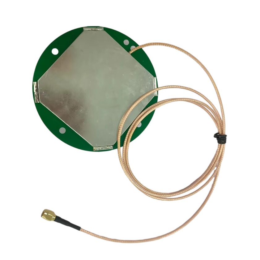
The design and construction of a multi-band RTK antenna with a FAKRA connector is a sophisticated exercise in electromagnetic engineering, materials science, and environmental robustness. It is far more than a simple piece of metal; it is a system of carefully tuned components working in harmony to perform a remarkably difficult task.
1. The Radiating Element: The Heart of the Antenna
The core of the antenna is the patch element, typically a metallic (often copper) patch printed on a dielectric substrate. For multi-band operation, a single patch is insufficient. Designers use several techniques:
Stacked Patches: A common method involves physically stacking multiple patch elements, each tuned to a different frequency band (e.g., a larger patch for L1 underneath a smaller patch for L2/L5). This allows for a compact form factor.
Slotted or Notched Patches: Precise slots or notches are cut into a single patch to perturb the current paths, exciting multiple resonant modes that correspond to the desired frequencies.
Feed Network: A sophisticated network of microstrip lines is designed beneath the patches to efficiently deliver the captured RF energy from each band to the output with minimal loss and proper phase alignment. This network is crucial for maintaining the antenna's phase center stability.
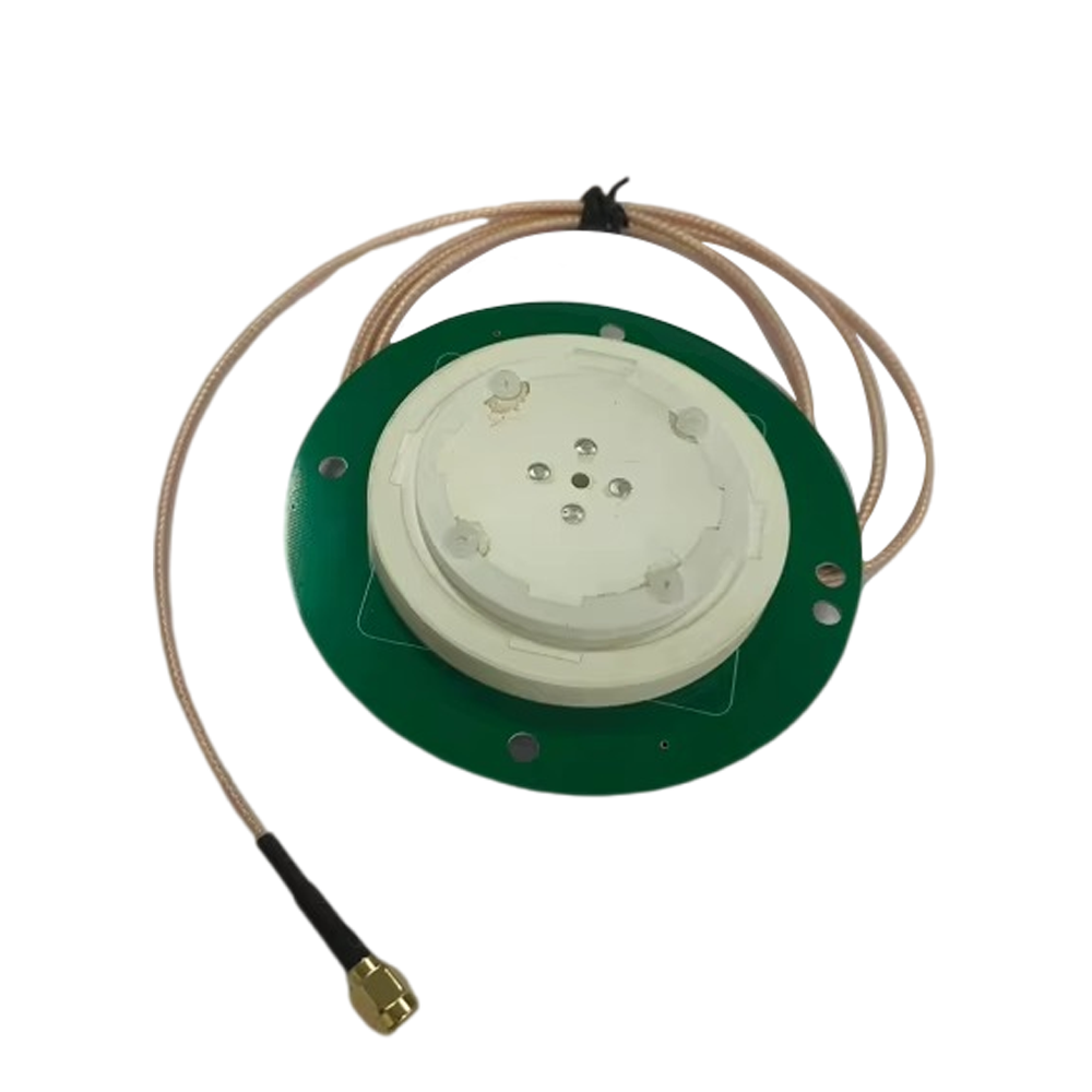
2. The Ground Plane: The Silent Guardian
Beneath the radiating element lies a critical component: the ground plane. This is a continuous sheet of metal that serves multiple purposes:
Directionality: It shapes the antenna's radiation pattern, making it directional—specifically, hemispherical. It maximizes gain toward the sky (where the satellites are) and minimizes gain toward the ground and the horizon, which are primary sources of multipath error (signals reflecting off the ground or the car's body).
Shielding: It acts as an electromagnetic shield, blocking noise and interference from the vehicle's own electronics (e.g., the infotainment system, motor controllers).
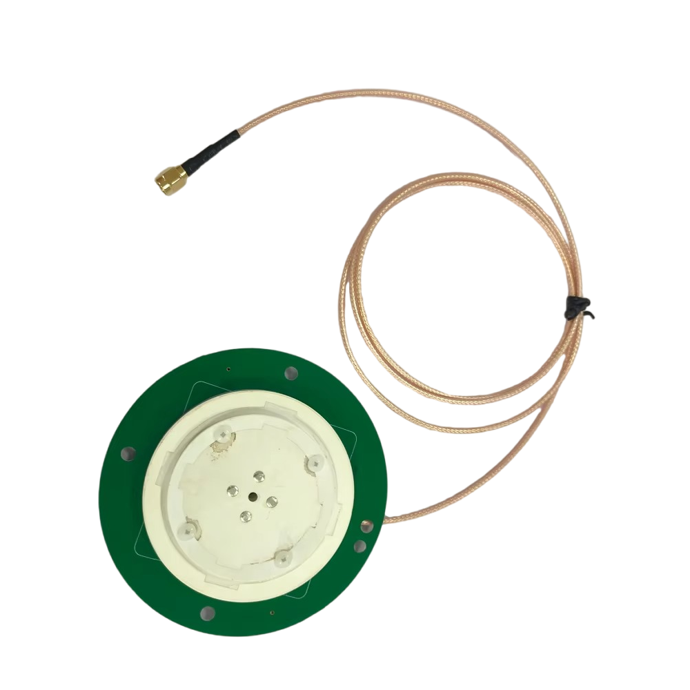
3. The Antenna Package: Ruggedization and Protection
The delicate internal electronics are encased in a radome, a protective shell that is transparent to RF signals. The material (often ceramic or high-grade plastic like Polyetherimide (PEI)) is chosen for its low dielectric constant and loss tangent to avoid attenuating the signals. The entire assembly is potted with a waterproof, shock-absorbing compound to protect against moisture ingress (humidity, rain, car washes), thermal expansion/contraction, and vibration, ensuring longevity over the vehicle's lifespan.
4. The Low-Noise Amplifier (LNA): The First Signal Boost
Embedded within the antenna housing, and often integrated directly onto the antenna's PCB, is a Low-Noise Amplifier (LNA). This is a critical active component. The signals from GNSS satellites are incredibly weak by the time they travel over 20,000 km to Earth. The LNA's job is to amplify these faint signals significantly (e.g., 25-40 dB gain) before they travel down the coaxial cable, where they would otherwise be degraded by cable loss. Crucially, the LNA must do this while adding the absolute minimum amount of its own electronic noise (measured as a Noise Figure), as any noise added at this first stage is amplified by all subsequent stages.
5. The FAKRA Connector System: The Automotive Interface
The amplified signal is fed through a short, high-quality cable to the FAKA connector. The FAKRA system's design is integral to the antenna's performance:
Color Coding (Blue for GPS): The standard blue connector (FAKRA Z) is universally designated for GNSS/GPS systems, preventing misconnection.
Keying: The internal plastic key ensures the connector can only be inserted in one orientation, guaranteeing proper pin alignment.
Locking Mechanism: A sliding collar or latch provides an audible "click" when securely mated, preventing accidental disconnection from vibration.
Shielding: The entire connector is metal-shielded to prevent RF leakage and external electromagnetic interference (EMI) from corrupting the sensitive GNSS signal on its final journey to the receiver.
The entire construction is a balance of competing demands: achieving wide bandwidth and perfect phase performance for multiple bands, while being physically small, aerodynamically neutral, aesthetically acceptable, and able to survive temperatures from -40°C to +85°C, all at a cost viable for mass-market automotive production.
The operation of a multi-band RTK antenna is the first and most critical step in a complex chain of events that culminates in centimeter-accurate positioning. Its working principle can be understood by separating its two primary functions: that of a sophisticated multi-band antenna and that of the starting point for RTK correction.
1. The Multi-Band GNSS Receiver Function:
A GNSS satellite transmits navigation signals on several carrier frequencies. The most common are:
L1 Band (~1575 MHz): Carries the Coarse/Acquisition (C/A) code for standard positioning and, on newer satellites, the encrypted precise (P/Y) code and civilian L1C signal.
L2 Band (~1227 MHz): Primarily carries the P/Y code, but also newer civilian codes like L2C.
L5 Band (~1176 MHz): A modern "safety-of-life" signal with higher power, greater bandwidth, and advanced coding for improved accuracy and robustness.
A standard antenna might only receive L1. A multi-band antenna receives L1, L2, and L5 (and their Galileo, GLONASS, and BeiDou equivalents) simultaneously. The key advantage is that the ionospheric delay—a major error source—is frequency-dependent. The delay is inversely proportional to the square of the frequency. By measuring the difference in the arrival time of the same signal on two different frequencies (e.g., L1 and L2), the receiver can precisely calculate the ionospheric delay error and eliminate it from the calculation. This dual-frequency operation is the primary enabler of high precision.
2. The Role in the RTK Engine:
RTK requires two antennas: a rover (on the car) and a stationary base station (at a known, fixed location).
Base Station: The base station antenna, knowing its exact position, receives the GNSS signals and calculates the error in the measured pseudoranges (the apparent distances to the satellites). It generates a stream of correction data that represents the real-time error for each satellite in view.
Rover (Car Antenna): The multi-band antenna on the car receives the same GNSS signals. However, its primary job is to capture the raw, unprocessed carrier phase measurements with extreme fidelity. The carrier phase is the precise measurement of the fractional wavelength of the signal, allowing for millimeter-level measurement—but it is ambiguous by an integer number of wavelengths (the "integer ambiguity").
Data Link: The base station's correction data is transmitted to the rover via a cellular, radio, or satellite link.
RTK Processing: The rover's receiver combines its own raw carrier phase measurements with the corrections from the base station. By resolving the integer ambiguity (a complex mathematical process), it can determine the precise vector between the base station and the rover, resulting in a centimeter-accurate position for the rover antenna.
The multi-band antenna's critical role in this process is threefold:
Capture All Signals: It must provide a strong, clean signal for all available satellites on all bands to maximize the number of measurements, which improves solution reliability and allows the integer ambiguity to be resolved faster (a concept known as Time-To-First-Fix - TTFF).
Preserve Phase Coherence: The antenna must have a stable and well-defined phase center. This is the imaginary point from which the signal appears to emanate. If this point moves with signal angle, frequency, or time, it introduces errors that the RTK engine cannot distinguish from real positioning errors. Multi-band antennas are meticulously designed to have a phase center that is consistent across all bands and all angles of arrival.
Minimize Multipath: The antenna's radiation pattern and ground plane are engineered to reject signals arriving from low elevations (below 5-10°), which are likely to be reflections (multipath) from the ground or the car's hood, rather than direct line-of-sight signals from satellites.
In essence, the antenna acts as the "ears" of the RTK system. It must listen keenly to the faint whispers of satellites across the entire spectrum while ignoring the noisy chatter of reflections and electronic interference, delivering a perfect, unadulterated signal to the brain (the receiver) for processing.
The adoption of multi-band RTK antennas with FAKRA connectors brings immense advantages to automotive positioning but is not without its significant technical and economic challenges.
Advantages:
Unparalleled Accuracy: The primary advantage is centimeter-level positioning accuracy in real-time. This is the non-negotiable requirement for lane-level navigation, autonomous vehicle control, and precise V2X coordination.
Rapid Convergence and Reliability: Multi-band signals drastically reduce the time required to resolve the integer ambiguity (TTFF). Even in challenging environments like urban canyons, having signals from multiple constellations and bands increases the probability of maintaining a "fixed" RTK solution, preventing dangerous fallbacks to less accurate modes.
Ionospheric Error Elimination: As described, this is the single biggest error source neutralized by multi-band technology, making the system globally consistent without relying on imperfect atmospheric models.
Robustness to Multipath: The advanced design of these antennas, with their controlled radiation patterns and high rejection of low-angle signals, makes them inherently more resistant to multipath errors than simple patch antennas.
Automotive Integration Standardization: The FAKRA connector solves a critical integration problem. It ensures a reliable, weatherproof, and mistake-proof RF connection that can be installed on the assembly line quickly and correctly, every time. It future-proofs the vehicle for adding other RF systems.
Challenges:
Cost: This is the most significant barrier to mass adoption. Multi-band antennas are inherently more complex to design and manufacture than single-band antennas. They require more expensive materials (high-quality dielectric substrates), more sophisticated LNAs that work across multiple bands, and rigorous testing and calibration. The FAKRA connector itself adds cost compared to a simple solder connection.
Complexity and Size: Accommodating multiple resonant elements and a complex feed network can lead to a larger physical footprint than a single-band antenna. Automotive designers are constantly battling for space on the roof or dash, making antenna size a critical factor.
Power Consumption: The integrated LNA requires a DC bias voltage supplied from the receiver through the coaxial cable (a system called "bias-tee"). While minimal, it is nonzero and must be considered in the vehicle's overall power budget, especially for always-on systems.
Calibration and Phase Center Variation (PCV): For the highest levels of accuracy, the precise phase center offset and variation of each antenna model must be characterized across all frequencies and elevation angles. This data must be provided to the RTK engine to apply corrections. This calibration process is time-consuming and adds to the cost.
Dependence on Correction Data Link: The antenna itself is only half the system. The RTK correction data must be delivered reliably and with low latency. This requires a robust, continuous, and widespread cellular data connection (or other link), which can be a challenge in remote areas or regions with poor coverage, introducing a system-level vulnerability.
The applications for this technology are vast and growing, extending far beyond simple navigation.
Current and Near-Future Applications:
Autonomous Driving (AD) and ADAS: The core application. Centimeter accuracy is essential for lane keeping, automated lane changes, highway autopilot, and any SAE Level 3+ functionality. It allows the vehicle to create and maintain a precise localization layer within its High-Definition (HD) map.
Precision Agriculture and Machinery: While not strictly a "car," autonomous tractors and harvesters use this exact technology for precision planting, fertilizing, and harvesting, optimizing yield and reducing waste.
V2X Communication: For Vehicle-to-Vehicle (V2V) collision avoidance or Vehicle-to-Infrastructure (V2I) coordination (e.g., priority at traffic lights), all vehicles must share a common, hyper-accurate understanding of their location. A standard GPS position is too vague for this purpose.
Advanced Logistics and Fleet Management: Tracking the exact location of high-value assets, monitoring yard vehicle movements for efficiency, and enabling automated truck platooning.
Robotics and Drones: Automotive-grade antennas are being adopted in autonomous mobile robots (AMRs) for warehouses and last-mile delivery drones, where cost, size, and reliability are paramount.
Future Trends:
Tighter Integration (AIO - Antenna-in-One): The trend is towards integrating the GNSS antenna with other automotive antennas (e.g., 5G/V2X, Wi-Fi, Bluetooth) into a single, streamlined "shark-fin" or blade module. This reduces drag, saves space, and simplifies assembly. This requires advanced filtering to prevent the powerful cellular transmitter from desensitizing the ultra-sensitive GNSS receiver.
Dead Reckoning Fusion: GNSS signals are prone to occlusion. Future systems will tightly couple the RTK position with on-board sensors like Inertial Measurement Units (IMUs), wheel odometry, and camera data in a sophisticated sensor fusion algorithm. This provides continuous, high-accuracy positioning even during short GNSS dropouts in tunnels or under bridges.
Cloud-Enhanced RTK and PPP-RTK: The future lies in moving beyond single base stations. Networks of base stations (CORS networks) can provide correction data over a wide area via the cloud. PPP-RTK (Precise Point Positioning with RTK) is an emerging technique that delivers precise satellite orbit and clock corrections along with atmospheric models, potentially allowing for centimeter accuracy without a nearby physical base station, reducing infrastructure dependency.
Resilience and Security: As positioning becomes safety-critical, antennas and receivers must be designed for resilience against intentional jamming (blocking signals) and spoofing (mimicking signals to provide false位置). This involves incorporating advanced signal processing techniques to detect and mitigate these attacks.
Cost Reduction through Mass Production: As demand from the automotive industry skyrockets, economies of scale will inevitably drive down the cost of multi-band antennas and receivers, making this technology standard on even mid-range vehicles.
Conclusion
In conclusion, the multi-band RTK antenna with a FAKRA connector is a masterpiece of modern engineering that represents a critical convergence point. It merges the unparalleled precision of satellite surveying technology with the harsh, cost-conscious, and standardized world of automotive manufacturing. It is far more than a simple accessory; it is the fundamental data-gathering gateway that transforms the abstract concept of "location" into a precise, reliable, and actionable metric.
By leveraging multiple satellite constellations and frequency bands, it provides the raw data necessary to eliminate dominant error sources, enabling the centimeter-level accuracy that is the bedrock of autonomous driving and advanced connected vehicle systems. The FAKRA connector, while seemingly a simple interface, is the linchpin that ensures this sophisticated technology can be reliably and efficiently integrated into millions of vehicles on a production line.
The challenges of cost, complexity, and system dependency remain, but they are being actively addressed by relentless innovation and the powerful driving force of market demand. As we move toward a future dominated by automated vehicles and intelligent transportation systems, this unassuming component, perched on the roof of a car, will play an outsized role in making that future safe, efficient, and reality. It is a definitive example of how a deeply specialized component can become a key enabler for a technological revolution.

 86 0755 2819 9597
Lucy Yang | lucy.y@toxutech.com
Nicole Li | nicole@toxutech.com
Dotty Zhao | sales04@toxutech.com
Global Business Director / Sales Team / Global Operations


 En
En Cn
Cn Korean
 Home >


