

-
Products -PCBA Manufacturing RF Connectors RF Cable Assemblys Embedded Antennas External Antennas Positioning Chips and Modules
RF Connectors

RF Cable Assemblys
Embedded Antennas
External Antennas
Positioning Chips and Modules


 Language


Language


In the relentless pursuit of smaller, smarter, and more connected devices, the demand for compact yet high-performance wireless solutions has never been greater. From advanced automotive telematics and in-car infotainment systems to portable trackers, drones, and industrial IoT sensors, there is a pervasive need for devices that can determine their location and communicate that data reliably. This functionality rests on the seamless integration of two critical wireless technologies: Global Navigation Satellite Systems (GNSS), including GPS (USA) and Glonass (Russia) for positioning, and 4G LTE (Long-Term Evolution) for high-speed cellular data communication. The multi-band GPS Glonass 4G ceramic chip antenna is a specialized component engineered to meet this exact need in a single, miniaturized, and surface-mount package.
Unlike traditional bulky antennas, ceramic chip antennas leverage high-dielectric-constant (high-εr) materials to miniaturize their physical footprint while maintaining high efficiency. For instance, the Taoglas GSA.884 series integrates GPS L1/L2 and GLONASS L1/L2 bands with 4G LTE Bands 1/3/7/20 in a 5.0 x 3.2 x 1.2 mm package, making it suitable for space-constrained designs. Similarly, the Pulse Electronics W3010 supports GPS/GLONASS/BeiDou and 4G LTE in a 4.0 x 2.0 x 0.8 mm form factor, demonstrating the industry’s push toward ultra-compact solutions.
The global market for high-precision GNSS antennas is projected to grow at a CAGR of 12.3% through 2030, driven by demand from autonomous systems, precision agriculture, and smart infrastructure. This overview explores the technological foundations, design innovations, and emerging applications of GPS/GLONASS 4G ceramic chip antennas, highlighting their role in enabling next-generation connected devices.
This antenna is not a single-purpose component but a highly integrated solution. The "multi-band" designation is crucial:
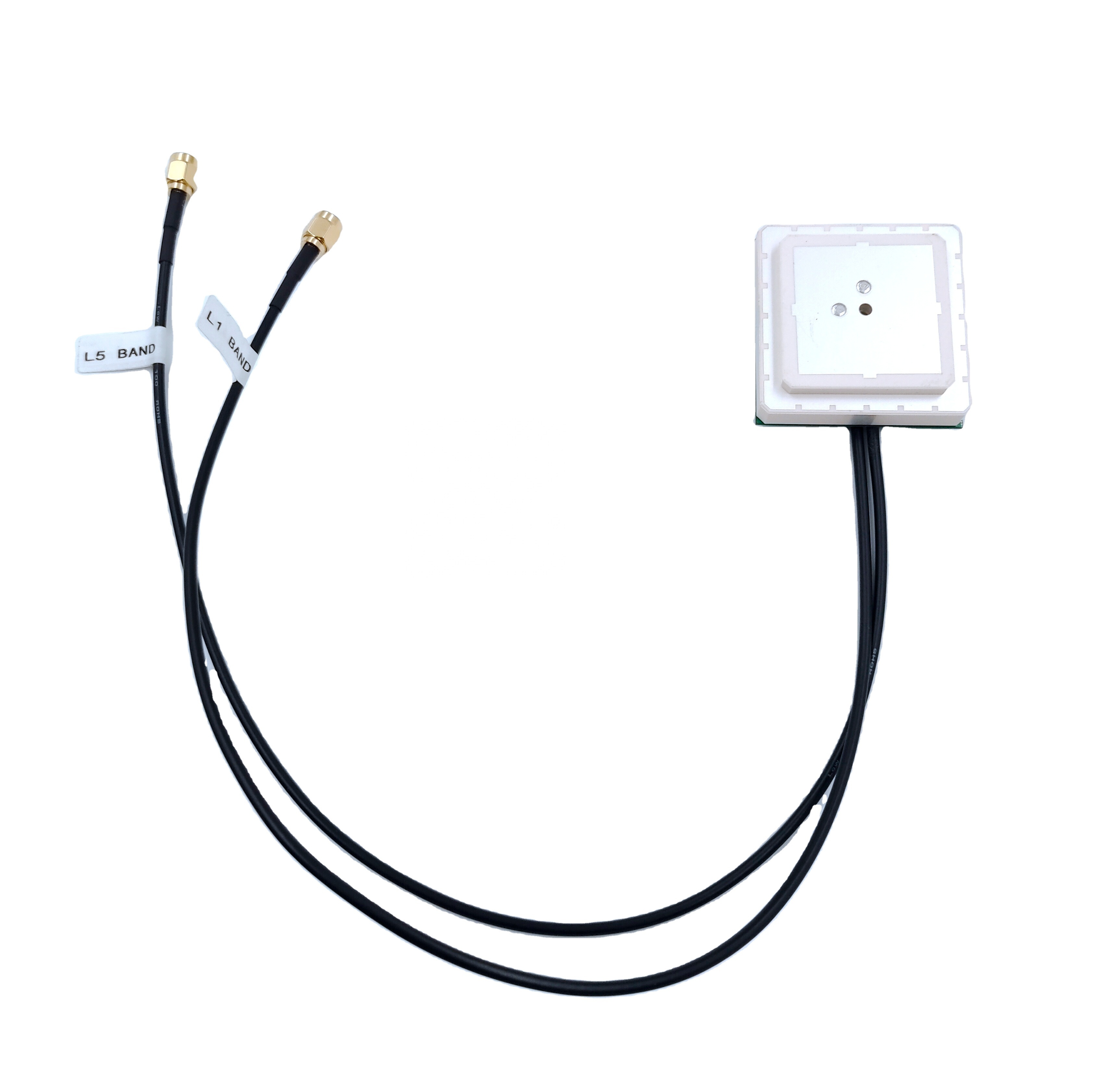
GNSS Bands (Receive-Only): It is designed to efficiently receive signals in the L1 band (1575.42 MHz for GPS, 1602 MHz for Glonass) and often extends to other GNSS frequencies like L2 (1227.60 MHz) or L5 (1176.45 MHz) for higher accuracy applications. Supporting multiple constellations (GPS + Glonass) significantly improves performance by increasing the number of visible satellites, leading to faster time-to-first-fix (TTFF), better accuracy, and enhanced reliability, especially in challenging urban canyon environments where the view of the sky is obstructed.
4G LTE Bands (Transmit and Receive): Simultaneously, the antenna must operate across a wide range of cellular frequencies used by 4G networks globally. This includes low-band (e.g., 700 MHz, 800 MHz) for long-range and building penetration, mid-band (e.g., 1800 MHz, 2100 MHz, 2600 MHz) for a balance of coverage and capacity, and high-band (e.g., 2300 MHz) for high data throughput. The antenna must handle both downlink (receive) and uplink (transmit) frequencies, which is a more demanding task than receive-only operation.
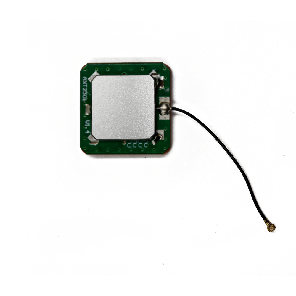
The "ceramic chip" form factor is what makes this antenna so revolutionary for product design. Unlike traditional external whip or patch antennas, this antenna is a passive, surface-mount device (SMD) made from a high-grade ceramic substrate. It is incredibly small, often measuring just 10mm x 10mm x 4mm, allowing it to be mounted directly onto a printed circuit board (PCB) like any other component. This eliminates the need for external cables and connectors, reduces assembly time and cost, improves reliability by removing moving parts, and enables sleek, compact, and sealed product designs. This overview positions the multi-band GPS Glonass 4G ceramic chip antenna as the enabling technology for a new generation of small, hidden, and always-connected intelligent devices.
The design and construction of a multi-band GPS Glonass 4G ceramic chip antenna is a sophisticated feat of electromagnetic engineering and materials science. It represents a complex compromise between achieving wide bandwidth, high efficiency, small size, and robust performance across vastly different frequency bands.
1. The Ceramic Core:
The foundation of the antenna is its ceramic dielectric material, typically a blend of titanium dioxide or other metal oxides. This is the key to its miniaturization. The high dielectric constant (εr) of the ceramic, often ranging from 10 to 40, slows down the propagation of electromagnetic waves within the material. This allows the physical length of the antenna's resonant elements to be significantly reduced compared to an antenna operating in free space (where εr = 1). A higher dielectric constant allows for a smaller antenna but typically at the cost of bandwidth and efficiency. Therefore, selecting the precise ceramic composition is a critical first step in the design process, balancing size constraints with performance requirements.
2. The Radiating Element:
The antenna's radiating structure is created by firing a silver-based conductive ink onto the surface of the ceramic block in a precise pattern. This pattern is not a simple patch; it is a complex, often multi-layered, and carefully meandered trace designed to create multiple resonant paths. For a dual-function antenna, the design is exceptionally challenging:
GNSS Element: The trace must be tuned to resonate at the precise, narrow GNSS frequencies (~1575 MHz, ~1602 MHz). This element must be highly efficient as it is receiving extremely weak signals from satellites.
4G LTE Element: The trace must be designed to excite multiple resonant modes to cover the wide spectrum of 4G bands, from ~700 MHz to ~2700 MHz. This often involves creating a multi-branched or coupled structure. Techniques like slit-loading and meandering are used to pack these long electrical paths into a small physical area.
3. The Ground Plane Dependency:
Unlike a standalone antenna with its own ground, a chip antenna is heavily dependent on the PCB it is mounted on. The PCB's ground plane acts as a critical part of the antenna system. Its size, shape, and layout directly influence the antenna's performance, radiation pattern, bandwidth, and efficiency. The antenna's datasheet provides strict guidelines on the required PCB ground plane dimensions and the keep-out area (a zone free of other components and metal) around the antenna. Deviating from these guidelines can detune the antenna, drastically reducing its performance. This symbiotic relationship with the host PCB is a fundamental aspect of its construction and application.
4. Internal Architecture:
More advanced ceramic chip antennas may incorporate internal matching networks or even multiple feed points to better isolate the different frequency bands and improve overall efficiency. The goal is to present a 50-ohm impedance to the RF front-end circuitry across all operating bands, minimizing signal reflection and maximizing power transfer.
5. Protective Coating:
The final assembly is typically coated with a protective layer of epoxy or other non-conductive material. This coating shields the delicate silver radiating element from moisture, dust, mechanical abrasion, and oxidation, ensuring long-term reliability in harsh operating environments.
The working principle of a multi-band ceramic chip antenna revolves around the fundamental physics of resonance and efficient energy conversion, all within a dramatically miniaturized form factor.
1. The Principle of Resonance:
An antenna operates most efficiently when its physical dimensions are a specific fraction (e.g., 1/4 wavelength) of the wavelength of the RF signal it is intended to transmit or receive. The wavelength (λ) is calculated as the speed of light (c) divided by the frequency (f). For example, the GPS L1 frequency of 1575 MHz has a wavelength of approximately 19 cm. A traditional 1/4 wavelength antenna would be about 4.75 cm long. The ceramic chip antenna achieves electrical resonance at this frequency without the physical length. The high dielectric constant effectively "traps" the electric field within the ceramic body, slowing the wave and allowing the internal conductive trace to interact with a much longer electrical wavelength than its physical size would suggest. It acts as a resonator, storing and releasing electromagnetic energy at its designed frequencies.
2. Reception (GNSS Operation):
The process begins with electromagnetic waves from GNSS satellites, which have traveled over 20,000 km and are incredibly weak. These waves impinge upon the ceramic chip antenna. The precisely shaped radiating element for GNSS captures this energy, causing electrons to oscillate at the specific L1 and L2/L5 frequencies. This oscillation creates a tiny, alternating electrical current at the antenna's feed point. This minuscule current, representing the satellite signal, is then passed through a matching network and delivered via a transmission line on the PCB to the GNSS receiver module. The receiver then amplifies, filters, and processes this signal to calculate precise timing and location data.
3. Transmission and Reception (4G LTE Operation):
For 4G LTE, the antenna operates in full duplex (can send and receive simultaneously on closely spaced frequencies).
Transmit (Uplink): The 4G modem generates an RF signal carrying data. This signal is amplified by a power amplifier (PA) and delivered to the antenna's 4G feed point. The antenna's 4G radiating element converts this electrical energy into electromagnetic waves, which are radiated outwards towards the nearest cellular base station.
Receive (Downlink): The reverse process occurs simultaneously. electromagnetic waves from the base station are captured by the antenna's 4G element, converted into an electrical current, and sent to a low-noise amplifier (LNA) in the modem to be processed.
4. Isolation and Coexistence:
A critical challenge is preventing the powerful transmitted 4G signal from overloading and desensitizing the highly sensitive GNSS receiver. While some isolation is achieved by the physical separation of the internal trace elements, the primary mitigation occurs on the PCB itself. This includes:
Band-Pass Filters: Placing filters on the feed lines for both the GNSS and 4G paths. A filter on the GNSS line will block strong 4G signals from entering the GNSS receiver, while a filter on the 4G transmit path will ensure a clean output signal.
Careful PCB Layout: Separating the RF transmission lines for GNSS and 4G and ensuring proper grounding to minimize coupling between them.
Advantages:
Extreme Miniaturization: The primary advantage is its incredibly small size, enabling product designs that would be impossible with external antennas.
Low Profile and Aesthetics: As a surface-mount component, it is hidden within the device's housing, resulting in sleek, consumer-friendly products with no protruding parts.
High Reliability: With no moving parts, cables, or connectors—common points of failure in traditional antennas—the ceramic chip antenna is highly resistant to shock, vibration, and wear, making it ideal for automotive and industrial applications.
Simplified Assembly and Reduced Cost: It can be picked and placed by automated assembly robots simultaneously with other PCB components, drastically reducing manufacturing labor costs compared to installing and wiring a separate antenna.
Design Flexibility: Engineers have more freedom to design the product's form factor without being constrained by the placement of an external antenna.
Challenges:
Performance Trade-offs: The small size and high dielectric constant inherently limit bandwidth and efficiency. These antennas are generally less efficient than larger external antennas, which can impact range and data rates, particularly in areas with weak signal strength.
Ground Plane Dependency: Performance is not intrinsic to the antenna alone. It is highly susceptible to the PCB layout, the size of the ground plane, and the proximity of other components. This requires extensive and careful RF design and testing for each new product, negating some of the "drop-in" simplicity.
Narrow Bandwidth: While designs have improved, covering the vast range of global 4G LTE bands with high efficiency in such a small package remains a immense challenge. Designers often have to accept performance dips in某些 bands.
Susceptibility to Detuning: The antenna's performance can be easily detuned by the surrounding environment. A user's hand gripping the device, the device's placement near a metal surface, or even the device's own housing can shift the resonant frequency and degrade performance, making consistent real-world performance difficult to guarantee.
Thermal Considerations: During prolonged 4G transmission at high power, the ceramic body can heat up due to dielectric losses, which can slightly alter its properties and affect performance.
Applications:
Automotive Telematics: Used in black boxes, insurance dongles (UBI), and fleet management trackers for location tracking and data transmission, often hidden from view.
Portable Personal Trackers: Compact devices for tracking assets, pets, or people.
Drones and UAVs: Where size, weight, and aerodynamics are critical, these antennas provide essential comms and GPS for navigation.
Industrial IoT (IIoT) Sensors: Deployed in smart agriculture, manufacturing, and logistics for remote monitoring and control.
Consumer Electronics: In wearable devices, portable POS systems, and ruggedized tablets.
Smart Meters: For remote reading and management by utility companies.
Future Trends:
5G Integration: The next evolution is the multi-band GNSS + 5G ceramic chip antenna. This is a monumental challenge due to 5G's new frequency bands (including sub-6 GHz and mmWave) and its requirement for Multiple-Input Multiple-Output (MIMO) antenna arrays. We will see modules with multiple integrated chip antennas to form 4x4 or 8x8 MIMO systems.
Active Integrated Antennas (AIA): Future iterations will integrate active components like LNAs and PAs directly into the antenna package or onto the immediate substrate, creating a more self-contained and optimized "antenna solution" rather than just a passive component.
Enhanced Materials: Research into new ceramic and substrate materials with more favorable loss tangents and tunable dielectric constants will continue to push the performance boundaries of small antennas.
Intelligent Impedance Matching: Incorporation of tunable matching networks (using varactors or RF switches) that can dynamically adjust the antenna's impedance in real-time to compensate for detuning caused by the environment (e.g., a hand grip), ensuring consistent performance.
Standardization of "Antenna-on-Chip": Further integration with RF semiconductor processes, potentially leading to antennas being deposited directly onto the chip package itself, although this technology faces significant efficiency hurdles.
Conclusion
The multi-band GPS Glonass 4G ceramic chip antenna is a testament to the incredible innovation in RF component design. It successfully condenses the complex functionality of multiple antennas into a single, tiny, and robust surface-mount package, solving a critical spatial challenge for modern electronic devices. By enabling precise location awareness and reliable cellular communication in a form factor that can be hidden away, it has become a pervasive enabler of the Internet of Things, connected automotive solutions, and portable consumer technology.
While it presents significant engineering challenges related to performance, bandwidth, and environmental sensitivity, its advantages in miniaturization, cost-effective manufacturing, and design flexibility are overwhelming for a vast array of applications. As wireless technology advances toward 5G and beyond, the ceramic chip antenna will continue to evolve, integrating more functions, becoming more efficient, and incorporating smarter active tuning techniques. It will remain an indispensable component in the ongoing mission to make devices smaller, smarter, and more seamlessly connected to the world around them. It is the unsung hero, quietly and efficiently linking our smallest devices to the global infrastructure of satellites and networks.

 86 0755 2819 9597
Lucy Yang | lucy.y@toxutech.com
Nicole Li | nicole@toxutech.com
Dotty Zhao | sales04@toxutech.com
Global Business Director / Sales Team / Global Operations


 En
En Cn
Cn Korean
 Home >


