

-
Products -PCBA Manufacturing RF Connectors RF Cable Assemblys Embedded Antennas External Antennas Positioning Chips and Modules
RF Connectors

RF Cable Assemblys
Embedded Antennas
External Antennas
Positioning Chips and Modules


 Language


Language


In the age of compact electronics and IoT (Internet of Things) proliferation, the demand for small, high-performance positioning components has skyrocketed—and the mini active GPS ceramic antenna solution stands out as a critical enabler of this trend. Unlike traditional GPS antennas (which are often large, passive, and limited to specific use cases), mini active GPS ceramic antennas combine ultra-compact size, integrated amplification, and reliable signal reception, making them ideal for devices where space, power efficiency, and positioning accuracy are non-negotiable. To fully grasp their significance, it is essential to break down their core definition, the market drivers behind their growth, and the unique value they bring to modern electronic systems.
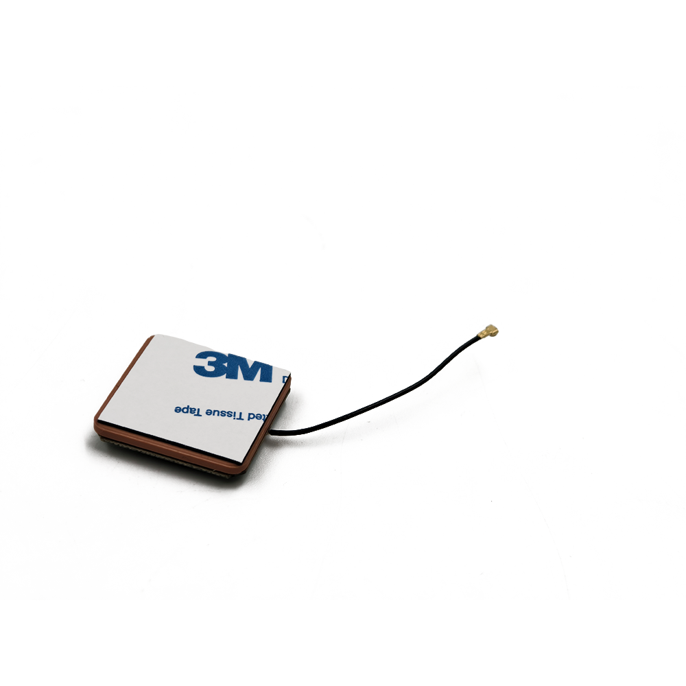
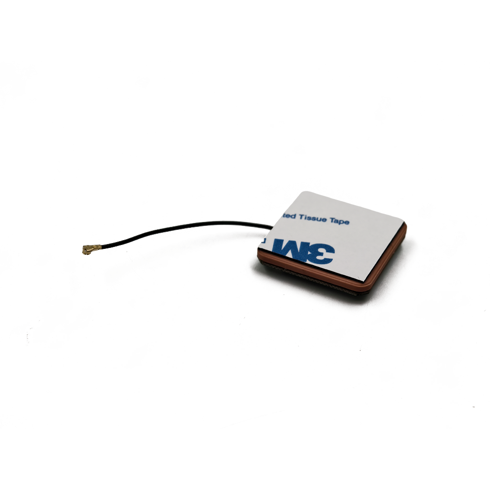
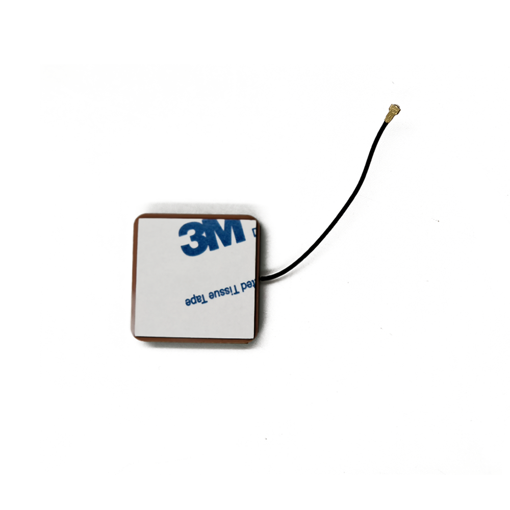
At its core, a mini active GPS ceramic antenna is a compact positioning device that combines two key elements: a ceramic antenna element (the component that captures GPS signals) and an integrated low-noise amplifier (LNA) (the component that boosts weak signals while minimizing interference). The "mini" descriptor refers to its size—typically ranging from 4mm × 4mm to 12mm × 12mm, with thicknesses as low as 1mm—making it small enough to fit in devices like smartwatches, asset trackers, and medical wearables. The "active" label distinguishes it from passive GPS antennas, which lack an integrated amplifier and rely on external signal boosting (a limitation that reduces their performance in weak-signal environments).
The growth of mini active GPS ceramic antenna solutions is driven by three major market trends: the expansion of IoT, the rise of wearable technology, and the demand for precise asset tracking. According to a 2024 report by Grand View Research, the global GPS antenna market is expected to reach $12.3 billion by 2030, with mini active ceramic variants accounting for over 35% of this growth—largely due to their suitability for IoT devices. IoT networks, which connect billions of small, battery-powered sensors (e.g., smart meters, environmental monitors, and logistics trackers), require positioning components that are tiny, energy-efficient, and capable of working in remote or urban environments where GPS signals may be weak. Wearable devices, such as fitness trackers and smartwatches, also rely on these antennas to provide location-based features (e.g., GPS navigation for runners, emergency location sharing) without adding bulk or draining batteries quickly.
Another key driver is the need for precision asset tracking across industries like logistics, healthcare, and automotive. In logistics, for example, mini active GPS ceramic antennas are embedded in shipping containers or packages to track their real-time location during transit—even in dense urban areas or inside warehouses (where signals are often blocked by walls or metal structures). In healthcare, they are used in medical wearables for patients with chronic conditions, allowing caregivers to monitor a patient’s location and ensure they stay within safe zones. In the automotive sector, they are integrated into compact telematics devices that track vehicle location, driver behavior, and maintenance needs.
It is important to distinguish mini active GPS ceramic antennas from other compact positioning solutions, such as patch antennas or helical antennas. While patch antennas are also used in small devices, they often lack the integrated LNA of active ceramic antennas, making them less effective in weak-signal environments. Helical antennas, on the other hand, offer higher gain but are larger and more power-hungry—making them unsuitable for ultra-compact devices. Mini active GPS ceramic antennas strike a balance: their ceramic element provides good signal reception (especially for GPS L1 band signals, which operate at 1575.42 MHz), while the integrated LNA ensures that even weak signals are amplified to a level that can be processed by a GPS receiver.
Regulatory standards also play a role in shaping these solutions. Most mini active GPS ceramic antennas must comply with global standards for electromagnetic compatibility (EMC) and radio frequency (RF) performance, such as the FCC (Federal Communications Commission) standards in the U.S. and CE (Conformité Européenne) standards in the EU. These standards ensure that the antennas do not interfere with other electronic devices and can operate reliably in different regions. Additionally, standards for power efficiency (e.g., IEEE 802.11ax for IoT devices) drive the design of low-power LNAs, which are critical for extending the battery life of wearable and IoT devices.
In summary, the mini active GPS ceramic antenna solution is a linchpin of modern compact electronics. Its combination of small size, integrated amplification, and reliable performance addresses the key needs of IoT, wearable, and asset-tracking markets. As these markets continue to grow, the demand for even smaller, more efficient, and more accurate variants will only increase—making this technology a focus of innovation for manufacturers and a critical component for developers of next-generation electronic devices.
The design and construction of a mini active GPS ceramic antenna solution are a masterclass in balancing size, performance, and power efficiency. Every component—from the ceramic substrate to the integrated LNA and the protective encapsulation—is engineered to meet the strict constraints of compact devices, while ensuring that the antenna can capture and amplify GPS signals reliably. This section breaks down the key design elements, materials, and manufacturing processes that define these solutions, as well as the trade-offs that engineers must navigate to optimize performance.
2.1 Core Components and Their Design
A mini active GPS ceramic antenna solution consists of three primary components: the ceramic antenna element, the integrated low-noise amplifier (LNA), and the matching network. Each component is designed to address specific challenges of compact positioning, and their integration is critical to the antenna’s overall performance.
2.1.1 Ceramic Antenna Element
The ceramic antenna element is the heart of the solution—it is responsible for capturing GPS L1 band signals (1575.42 MHz) and converting them into electrical signals that can be amplified by the LNA. The key to its design is the ceramic substrate, which is made from a high-dielectric-constant (high-εr) material—typically barium titanate (BaTiO3) or a composite of barium titanate and other ceramics. High-εr materials are used because they allow the antenna to be much smaller than traditional antennas: the dielectric constant of the substrate determines the wavelength of the signal within the material, and a higher εr means a shorter wavelength, which translates to a smaller antenna size. For example, a ceramic substrate with an εr of 20 can reduce the antenna’s size by a factor of √20 (approximately 4.5) compared to an antenna using air as the dielectric.
The ceramic element is designed as a patch antenna—a flat, rectangular structure that is printed or etched onto the ceramic substrate. The patch is made from a conductive material (usually silver or copper), and its dimensions (length, width, and thickness) are carefully calculated to resonate at the GPS L1 frequency. The length of the patch is typically λ/2 (half the wavelength of the GPS signal in the ceramic material), while the width is slightly larger to optimize impedance matching (a critical factor for maximizing signal transfer from the antenna to the LNA).
Another key design consideration is the ground plane—a conductive layer (often made of copper) that is placed on the opposite side of the ceramic substrate from the patch. The ground plane serves two purposes: it reflects the GPS signal back to the patch, enhancing signal reception, and it isolates the antenna from other electronic components in the device (which could cause interference). The size of the ground plane is typically larger than the patch (by 5-10% on each side) to ensure optimal performance.
2.1.2 Integrated Low-Noise Amplifier (LNA)
The LNA is the "active" component of the solution—it amplifies the weak electrical signals from the ceramic element (which are typically on the order of microvolts) while adding minimal noise. In mini active GPS ceramic antennas, the LNA is integrated directly onto the same substrate as the ceramic element (often using a hybrid integration approach, where the LNA is a surface-mount device (SMD) soldered to the substrate), which reduces size and eliminates the need for long signal traces (which can introduce noise or signal loss).
The design of the LNA is focused on two key parameters: noise figure (NF) and power consumption. The noise figure is a measure of how much noise the amplifier adds to the signal—lower NF values mean better performance in weak-signal environments. For mini active GPS ceramic antennas, the LNA typically has an NF of 0.8-1.5 dB, which is low enough to amplify weak GPS signals (e.g., signals from satellites low on the horizon) without obscuring them with noise. Power consumption is equally critical, as these antennas are often used in battery-powered devices (e.g., wearables, IoT sensors). The LNA is designed to operate on low voltages (typically 1.8-3.3 V) and draw minimal current (5-15 mA), ensuring that it does not drain the device’s battery quickly.
2.1.3 Matching Network
The matching network is a set of passive components (resistors, capacitors, and inductors) that connects the ceramic element to the LNA. Its role is to match the impedance of the antenna (which is typically 50 ohms for GPS applications) to the input impedance of the LNA (which may be different, depending on the LNA’s design). Impedance matching is critical because any mismatch between the antenna and the LNA will cause signal reflection, reducing the amount of signal that is amplified and processed.
The matching network is designed using simulation tools (e.g., ADS, HFSS) to optimize performance at the GPS L1 frequency. For mini active GPS ceramic antennas, the matching network is often implemented as a π-network (a configuration with two capacitors and one inductor) or an L-network (a configuration with one capacitor and one inductor), as these designs are compact and easy to integrate onto the small substrate. The components of the matching network are surface-mount devices (SMDs) with extremely small footprints (e.g., 0201 or 01005 size), which allows them to fit on the same substrate as the ceramic element and LNA.
2.2 Encapsulation and Packaging
Given their use in compact, often portable devices, mini active GPS ceramic antennas require robust encapsulation to protect the internal components from physical damage, moisture, and environmental interference. The encapsulation material and design are carefully chosen to balance protection with performance—since the material must not block or attenuate GPS signals.
The most common encapsulation material is epoxy resin (often a high-temperature, RF-transparent epoxy), which is applied over the ceramic element, LNA, and matching network. Epoxy resin is ideal because it is lightweight, durable, and has low RF loss (meaning it does not absorb or reflect GPS signals significantly). The epoxy is cured at high temperatures (typically 120-150°C) to form a hard, protective layer that can withstand physical impacts (e.g., drops or scratches) and exposure to moisture (with many designs meeting IP67 or IP68 waterproofing ratings for short-term submersion).
In some cases, especially for antennas used in harsh environments (e.g., industrial IoT sensors or automotive devices), the encapsulation may include an additional metal shield (made of aluminum or copper) around the LNA. The metal shield prevents electromagnetic interference (EMI) from other components in the device (e.g., microprocessors, batteries) from disrupting the LNA’s performance. The shield is designed with small openings or notches to allow GPS signals to pass through to the ceramic element, ensuring that signal reception is not compromised.
The packaging of the antenna is also optimized for easy integration into devices. Most mini active GPS ceramic antennas are designed as surface-mount technology (SMT) components, which means they can be soldered directly onto the device’s printed circuit board (PCB) using standard pick-and-place manufacturing processes. The SMT package has a small footprint (e.g., 6mm × 6mm × 1.5mm) and standardized pinouts (typically 2-4 pins for power, ground, signal input, and signal output), making it easy for device manufacturers to integrate the antenna into their designs without extensive customization.
2.3 Manufacturing Processes
The manufacturing of mini active GPS ceramic antenna solutions involves several precision steps, each requiring strict quality control to ensure consistency and performance.
2.3.1 Ceramic Substrate Fabrication
The process begins with the fabrication of the ceramic substrate. The high-εr ceramic material (e.g., barium titanate) is mixed with a binder (e.g., polyvinyl alcohol) to form a slurry, which is then pressed into a thin sheet (with a thickness of 0.5-1mm) using a hydraulic press. The sheet is cut into individual substrate pieces using a laser or die cutter, and then fired in a kiln at high temperatures (1200-1400°C) to densify the ceramic and remove the binder. This firing process ensures that the substrate has the correct dielectric constant and mechanical strength.
2.3.2 Patch and Ground Plane Deposition
Next, the conductive patch and ground plane are deposited onto the ceramic substrate. This is typically done using screen printing—a process where a thin layer of conductive ink (silver or copper) is printed onto the substrate through a stencil. The printed substrate is then fired again at a lower temperature (800-1000°C) to sinter the conductive ink, forming a durable, low-resistance layer. For higher precision (e.g., for antennas with dimensions smaller than 5mm × 5mm), sputtering (a physical vapor deposition process) may be used to deposit the conductive layer, as it allows for thinner, more uniform films.
2.3.3 LNA and Matching Network Integration
The LNA and matching network components are then integrated onto the substrate. The LNA is a pre-manufactured SMD chip, which is soldered to the substrate using reflow soldering—a process where the substrate is heated to a temperature above the melting point of the solder (typically 210-230°C), causing the solder paste to melt and bond the LNA to the substrate. The matching network components (SMD resistors, capacitors, inductors) are soldered in the same way, using a pick-and-place machine to place the tiny components (which can be as small as 0.25mm × 0.125mm) onto the substrate with high precision.
2.3.4 Encapsulation and Testing
Finally, the assembled antenna is encapsulated with epoxy resin, which is applied using a dispensing machine and cured in an oven. After encapsulation, the antenna undergoes rigorous testing to ensure it meets performance specifications. Key tests include:
RF performance testing: The antenna’s gain (signal amplification), return loss (impedance matching), and radiation pattern (signal coverage) are measured using an anechoic chamber (a room designed to eliminate RF reflections).
Noise figure testing: The LNA’s noise figure is measured using a noise figure analyzer, ensuring it meets the 0.8-1.5 dB range.
Environmental testing: The antenna is subjected to temperature cycling (from -40°C to 85°C), humidity testing (95% relative humidity at 60°C), and vibration testing to ensure it can withstand the conditions of its intended use.
These manufacturing processes and tests ensure that each mini active GPS ceramic antenna meets the strict performance and reliability requirements of compact electronic devices.
To understand how a mini active GPS ceramic antenna solution delivers accurate positioning data in compact devices, it is essential to unpack its working principles—from signal capture to amplified signal output. Unlike passive antennas, which rely on external amplification, these active solutions integrate all necessary components to capture, amplify, and prepare GPS signals for processing by a GPS receiver. This section breaks down the step-by-step operation of the antenna, as well as the key technologies that enable its performance in weak-signal environments and compact form factors.
3.1 Step 1: GPS Signal Capture by the Ceramic Element
The first step in the antenna’s operation is the capture of GPS signals from orbiting satellites. GPS satellites broadcast signals in the L1 band (1575.42 MHz) using a spread-spectrum modulation technique, which allows the signals to be detected even in the presence of noise or interference. The ceramic element—with its high-dielectric-constant substrate and printed patch— is specifically designed to resonate at this frequency, enabling it to efficiently capture the signals.
When a GPS signal reaches the ceramic element, it interacts with the conductive patch. The patch acts as a resonant cavity, where the incoming electromagnetic wave (the GPS signal) induces an alternating current (AC) in the patch. The frequency of this AC current matches the frequency of the GPS signal (1575.42 MHz), thanks to the patch’s carefully calculated dimensions (λ/2 length in the ceramic material). The ground plane on the opposite side of the ceramic substrate plays a critical role here: it reflects the incoming signal back to the patch, reinforcing the induced current and increasing the antenna’s ability to capture weak signals.
A key factor in signal capture is the radiation pattern of the ceramic element. Mini active GPS ceramic antennas typically have an omnidirectional radiation pattern in the horizontal plane (azimuth) and a directional pattern in the vertical plane (elevation). This means the antenna can capture signals from satellites in any direction along the horizon (which is important for urban environments, where satellites may be visible only in certain directions) while focusing on signals coming from above (since GPS satellites orbit at an altitude of ~20,000 km, their signals arrive at a downward angle). The radiation pattern is optimized during design using simulation tools to ensure that the antenna has maximum gain (signal reception strength) for signals coming from the upper hemisphere, where most GPS satellites are located.
In compact devices (e.g., smartwatches or asset trackers), the antenna’s placement within the device can affect signal capture. For example, if the antenna is placed near a metal component (e.g., a battery or a case), the metal can reflect or block GPS signals, reducing the antenna’s performance. To mitigate this, device manufacturers often place the antenna in a "clear" area of the PCB (away from metalcomponents) or use a "ground plane extension" (a small conductive trace that extends the antenna’s ground plane beyond the ceramic substrate) to reduce interference. Some devices also use a "metal frame integration" technique, where the device’s metal case is designed to act as an extension of the antenna’s ground plane, improving signal capture without adding size.
3.2 Step 2: Signal Transfer and Impedance Matching via the Matching Network
Once the ceramic element captures the GPS signal and converts it into an AC current, the signal must be transferred to the LNA with minimal loss. This is where the matching network plays a critical role. As mentioned earlier, the antenna’s impedance (typically 50 ohms) and the LNA’s input impedance (which may be 10-50 ohms, depending on the LNA’s design) often differ. If there is an impedance mismatch, a portion of the signal will be reflected back to the antenna instead of being transferred to the LNA—reducing the amount of signal available for amplification.
The matching network resolves this by acting as a "bridge" between the antenna and the LNA. It uses a combination of capacitors and inductors to adjust the impedance of the signal path, ensuring that the antenna’s output impedance matches the LNA’s input impedance at the GPS L1 frequency. For example, if the LNA has an input impedance of 25 ohms (lower than the antenna’s 50 ohms), the matching network may use a series inductor and a shunt capacitor to "transform" the 50-ohm impedance to 25 ohms. This transformation is calculated using complex impedance formulas and validated with simulation tools to ensure maximum signal transfer.
The efficiency of the matching network is measured by the return loss—a parameter that quantifies how much of the signal is reflected back to the antenna. A return loss of -10 dB or lower is considered acceptable for mini active GPS ceramic antennas, meaning that less than 10% of the signal is reflected and more than 90% is transferred to the LNA. This high transfer efficiency is critical for weak-signal environments, where even a small loss of signal can make it impossible for the LNA to amplify the signal to a usable level.
3.3 Step 3: Signal Amplification by the Integrated LNA
After the matching network transfers the signal to the LNA, the LNA amplifies the weak AC current (which is typically 1-10 microvolts) to a stronger voltage (usually 10-100 millivolts)—a gain of 20-40 dB. The key to the LNA’s performance is its ability to amplify the signal while adding minimal noise. As mentioned earlier, the LNA has a low noise figure (0.8-1.5 dB), which means that the noise introduced by the amplifier is much smaller than the signal itself. This is critical because GPS signals are often weaker than the background noise in the environment (e.g., noise from other electronic devices or atmospheric interference), and a high-noise amplifier would obscure the signal.
The LNA’s amplification process is based on transistor technology. Most LNAs for mini active GPS ceramic antennas use gallium arsenide (GaAs) or silicon germanium (SiGe) transistors, which offer low noise and high gain at RF frequencies. GaAs transistors are often preferred for high-performance applications (e.g., automotive or industrial IoT) because they have a lower noise figure and higher gain than SiGe transistors, but they are more expensive. SiGe transistors are used in cost-sensitive applications (e.g., consumer wearables) because they are cheaper and can be integrated with other silicon-based components on the same PCB.
The LNA also includes bias circuitry that provides the necessary voltage and current to power the transistor. The bias circuitry is designed to be energy-efficient, ensuring that the LNA operates on low voltages (1.8-3.3 V) and draws minimal current (5-15 mA). This is critical for battery-powered devices, where power consumption directly impacts battery life. For example, a smartwatch with a mini active GPS ceramic antenna that draws 10 mA of current from a 3.7 V battery will consume 37 milliwatts of power—far less than a passive antenna with an external amplifier that may draw 50-100 mA.
3.4 Step 4: Signal Output to the GPS Receiver
After amplification, the LNA outputs the strong, low-noise signal to the device’s GPS receiver. The output signal is typically a differential signal (two signals with opposite polarities) to reduce electromagnetic interference (EMI) during transmission from the antenna to the receiver. Differential signals are less susceptible to EMI because any noise that affects one signal will affect the other in the same way, and the receiver can subtract the noise out during processing.
The GPS receiver then processes the amplified signal to calculate the device’s position. This processing involves several steps:
Signal demodulation: The receiver extracts the satellite’s timestamp and ephemeris data (orbital information) from the amplified GPS signal.
Time delay calculation: The receiver measures the time it takes for the signal to travel from the satellite to the antenna (time of flight), using the satellite’s timestamp and the receiver’s internal clock.
Distance calculation: Using the speed of light (3 × 10^8 m/s), the receiver calculates the distance to the satellite (distance = speed of light × time of flight).
Trilateration: The receiver uses distances to at least four satellites to calculate the device’s 3D position (latitude, longitude, and altitude) using a mathematical technique called trilateration.
The mini active GPS ceramic antenna’s role ends once the amplified signal is delivered to the receiver, but its performance directly impacts the receiver’s ability to calculate an accurate position. A strong, low-noise signal from the antenna ensures that the receiver can demodulate the satellite data correctly and calculate time delays with high precision—leading to more accurate positioning (typically within 1-5 meters for civilian GPS applications).
Mini active GPS ceramic antenna solutions offer a unique set of advantages that make them indispensable for compact, battery-powered electronic devices. However, they also face significant challenges that limit their performance in certain environments and applications. Understanding these advantages and challenges is critical for device manufacturers, engineers, and end-users who rely on these antennas for positioning.
4.1 Key Advantages
4.1.1 Ultra-Compact Size for Space-Constrained Devices
The most obvious and impactful advantage of mini active GPS ceramic antennas is their small size. With dimensions ranging from 4mm × 4mm to 12mm × 12mm and thicknesses as low as 1mm, these antennas can fit into devices where space is at a premium—such as smartwatches, fitness trackers, medical wearables (e.g., glucose monitors), and small IoT sensors (e.g., asset trackers for packages). This is a significant improvement over traditional GPS antennas, which often require a footprint of 20mm × 20mm or larger—making them unsuitable for ultra-compact devices.
For example, a smartwatch with a 42mm case can easily integrate a 6mm × 6mm mini active GPS ceramic antenna into its PCB without sacrificing space for other components (e.g., the display, battery, or heart rate sensor). Similarly, a small asset tracker for shipping packages (which may be the size of a credit card) can use a 4mm × 8mm antenna to provide real-time location data without adding bulk. This compact size has enabled the development of new classes of devices that combine positioning with other features—such as smart glasses with GPS navigation or tiny environmental sensors that track location alongside temperature and humidity.
4.1.2 Integrated Amplification for Weak-Signal Performance
The integrated LNA is another key advantage of these antennas, as it enables reliable performance in weak-signal environments. Passive GPS antennas lack an integrated amplifier, so they rely on external amplification (which adds size and power consumption) or the receiver’s internal amplifier (which may have a higher noise figure). This makes passive antennas ineffective in environments where GPS signals are weak—such as urban canyons (where buildings block signals), indoor spaces (where walls and ceilings attenuate signals), or remote rural areas (where satellites are fewer and farther between).
Mini active GPS ceramic antennas, with their low-noise LNAs (0.8-1.5 dB), can amplify even the weakest signals (down to -160 dBm) to a level that the GPS receiver can process. For example, in a dense urban area where a passive antenna may only receive signals from 2-3 satellites (insufficient for positioning), a mini active antenna can receive signals from 4-6 satellites by amplifying weak signals from satellites low on the horizon. This improves positioning accuracy and reliability, making the antenna suitable for applications like urban navigation (e.g., for delivery drones) or indoor asset tracking (e.g., for medical equipment in hospitals).
4.1.3 Low Power Consumption for Battery-Powered Devices
Power efficiency is a critical advantage of mini active GPS ceramic antennas, as most of their target devices (wearables, IoT sensors) are battery-powered. The integrated LNA is designed to operate on low voltages (1.8-3.3 V) and draw minimal current (5-15 mA)—far less than external amplifiers, which may draw 50-100 mA. This low power consumption extends the battery life of the device, which is a key selling point for consumers and industrial users.
For example, a fitness tracker with a 200 mAh battery and a mini active GPS ceramic antenna that draws 10 mA of current when in use can operate for 20 hours on a single charge (assuming GPS is used continuously). In contrast, a fitness tracker with a passive antenna and an external amplifier that draws 60 mA would only operate for 3.3 hours on the same battery. This difference is significant for users who rely on their devices for all-day activity tracking or outdoor navigation.
Additionally, many mini active GPS ceramic antennas include power-saving modes that reduce current consumption when the antenna is not in use. For example, the LNA can be turned off when the device is in standby mode (e.g., a smartwatch that only uses GPS for occasional location checks), further extending battery life.
4.1.4 Easy Integration with Standard Manufacturing Processes
Mini active GPS ceramic antennas are designed as surface-mount technology (SMT) components, which means they can be integrated into devices using standard PCB manufacturing processes—such as pick-and-place assembly and reflow soldering. This is a major advantage for device manufacturers, as it eliminates the need for custom assembly processes or specialized tools.
The SMT package has a standardized footprint and pinout, making it easy for engineers to design the antenna into their PCB layouts. For example, a 6mm × 6mm antenna with a 4-pin configuration (power, ground, signal input, signal output) can be placed on the PCB using the same equipment used to place other SMD components (e.g., resistors, capacitors, microchips). This reduces manufacturing costs and lead times, as manufacturers do not need to invest in new equipment or training to integrate the antenna.
Furthermore, the antenna’s compact size and low profile (thickness < 2mm) make it easy to integrate into the device’s case without requiring special design modifications. For example, the antenna can be placed under the device’s display or battery, as long as there is a clear path for GPS signals to reach the ceramic element.
4.2 Key Challenges
4.2.1 Limited Gain Compared to Larger Antennas
While the integrated LNA provides amplification, the ceramic element itself has a lower gain than larger GPS antennas (e.g., helical antennas or external patch antennas). Gain is a measure of the antenna’s ability to capture signals in a specific direction—higher gain means the antenna can capture weaker signals from farther away. Mini active GPS ceramic antennas typically have a gain of 1-3 dBi, compared to larger antennas which may have a gain of 5-10 dBi.
This limited gain can be a problem in extremely weak-signal environments—such as deep indoor spaces (e.g., basements or underground warehouses) or areas with heavy foliage (e.g., forests). In these environments, even the LNA may not be able to amplify the signal enough for the GPS receiver to calculate a position. For example, in a basement warehouse, a mini active antenna may only receive signals from 1-2 satellites (insufficient for positioning), while a larger external antenna mounted on the warehouse roof could receive signals from 4-5 satellites.
To mitigate this challenge, some manufacturers offer "high-gain" mini active GPS ceramic antennas with a gain of 3-5 dBi, but these antennas are often larger (e.g., 12mm × 12mm) and more expensive. They also require a larger ground plane, which can be a problem for ultra-compact devices.
4.2.2 Sensitivity to Environmental Interference
Mini active GPS ceramic antennas are sensitive to electromagnetic interference (EMI) from other components in the device—such as microprocessors, batteries, displays, and wireless modules (e.g., Wi-Fi, Bluetooth). EMI can disrupt the GPS signal, causing the antenna to receive weaker signals or introducing noise into the amplified signal. This can reduce positioning accuracy or cause the GPS receiver to lose signal entirely.
For example, a smartwatch with a mini active GPS ceramic antenna placed near a Wi-Fi module may experience EMI from the Wi-Fi signal (which operates at 2.4 GHz or 5 GHz, close to the GPS L1 band of 1.575 GHz). This EMI can cause the antenna’s noise figure to increase, making it harder for the LNA to amplify the GPS signal. Similarly, a battery with a high current draw (e.g., a lithium-ion battery in a tablet) can generate EMI that disrupts the antenna’s signal capture.
To mitigate EMI, device manufacturers must carefully design the PCB layout to separate the antenna from high-EMI components. This may involve placing the antenna in a "quiet" area of the PCB (away from the microprocessor and wireless modules), using ground planes or shielding to block EMI, or adding filters to the antenna’s signal path. However, these measures can increase the device’s size and manufacturing costs—undermining the antenna’s key advantage of compactness.
4.2.3 Temperature Sensitivity of Ceramic Materials
The ceramic substrate used in the antenna element is sensitive to temperature changes, which can affect the antenna’s performance. Ceramic materials have a temperature coefficient of dielectric constant (TCε), meaning their dielectric constant changes with temperature. For example, barium titanate has a TCε of ~100 ppm/°C (parts per million per degree Celsius), which means its dielectric constant changes by 0.01% for every 1°C change in temperature.
This change in dielectric constant affects the antenna’s resonant frequency—since the resonant frequency is determined by the dielectric constant of the substrate and the dimensions of the patch. If the temperature increases, the dielectric constant increases, causing the resonant frequency to decrease. If the temperature decreases, the dielectric constant decreases, causing the resonant frequency to increase. This can shift the antenna’s resonant frequency away from the GPS L1 band (1575.42 MHz), reducing the antenna’s ability to capture signals.
For example, in a car parked in direct sunlight, the temperature inside the car can reach 60°C or higher. This can cause the antenna’s resonant frequency to shift by ~1.5 MHz (100 ppm/°C × 50°C × 1575.42 MHz = ~1.575 MHz), moving it outside the GPS L1 band. This would reduce the antenna’s gain by 3-6 dB, making it harder to capture signals. Similarly, in a cold environment (e.g., -30°C in a polar region), the resonant frequency could shift by ~4.7 MHz, causing similar performance issues.
To mitigate temperature sensitivity, manufacturers use ceramic materials with a low TCε (e.g., alumina-based ceramics with a TCε of ~10 ppm/°C) or add temperature-compensating materials to the substrate. However, these materials are often more expensive and can increase the antenna’s size. They also do not eliminate temperature sensitivity entirely—only reduce it.
4.2.4 Higher Cost Compared to Passive Antennas
Mini active GPS ceramic antennas are more expensive than passive GPS antennas, primarily due to the cost of the integrated LNA and the precision manufacturing processes required to integrate the LNA with the ceramic element. A passive GPS ceramic antenna may cost \(0.50-\)2.00 per unit, while a mini active GPS ceramic antenna costs \(2.00-\)5.00 per unit—up to 10 times more expensive.
This higher cost can be a barrier for cost-sensitive applications—such as low-cost IoT sensors (e.g., smart meters for utility companies) or disposable devices (e.g., temporary asset trackers for shipping). For example, a utility company that deploys 1 million smart meters may choose a passive antenna to save \(3 million-\)5 million in component costs, even if it means sacrificing performance in weak-signal environments.
To address this challenge, manufacturers are developing lower-cost LNAs using silicon-based transistors (e.g., CMOS) instead of GaAs or SiGe. CMOS LNAs are cheaper to manufacture and can be integrated with other silicon-based components on the same chip, reducing the overall cost of the antenna. However, CMOS LNAs have a higher noise figure (1.5-2.0 dB) than GaAs or SiGe LNAs, which can reduce performance in weak-signal environments.
Mini active GPS ceramic antenna solutions are already widely used in a variety of applications, thanks to their compact size, low power consumption, and reliable performance. As technology advances and new markets emerge, their applications will continue to expand, and new trends will shape their design and functionality. This section explores the current key applications of these antennas and the future trends that will drive their evolution.
5.1 Current Key Applications
5.1.1 Wearable Devices
Wearable devices—such as smartwatches, fitnesstrackers, and smart glasses—are among the most prominent applications of mini active GPS ceramic antennas, and for good reason. These devices demand ultra-compact components that can deliver reliable positioning without draining the battery, and mini active GPS ceramic antennas meet both criteria perfectly.
Smartwatches, for instance, use these antennas to enable location-based features like GPS navigation for outdoor activities (running, hiking, cycling), emergency location sharing (e.g., Apple Watch’s Emergency SOS or Samsung Galaxy Watch’s Safety Profile), and location-tagged fitness data (e.g., mapping a user’s running route with distance and pace). A typical smartwatch, with a case size of 40-46mm, can easily accommodate a 6mm × 6mm mini active GPS ceramic antenna—often placed under the display or near the watch’s edge, where signal reception is least obstructed by the battery or metal case. The antenna’s low power consumption (5-15 mA) is critical here: a smartwatch with a 300 mAh battery can use GPS continuously for 20-60 hours (depending on other features like display brightness) without needing a charge, which is essential for users on multi-hour outdoor adventures.
Fitness trackers, which are even smaller than smartwatches (some as small as 30mm × 15mm), rely on mini active GPS ceramic antennas to provide accurate distance and route tracking for activities like walking, running, and swimming. Many fitness trackers are water-resistant (up to 50 meters or more), and the antenna’s encapsulation (often IP68-rated) ensures it can withstand submersion without performance loss. For example, a fitness tracker like the Garmin Forerunner 158 uses a mini active GPS ceramic antenna to track running routes with sub-10-meter accuracy, even in urban areas with tall buildings.
Smart glasses—such as Google Glass Enterprise Edition or Vuzix Shield—use mini active GPS ceramic antennas to enable hands-free navigation for industrial workers, field technicians, or outdoor enthusiasts. These glasses have extremely limited space for components (the frame width is often less than 150mm), so the antenna’s small size (e.g., 4mm × 8mm) is a perfect fit. The antenna provides real-time location data, which is overlaid on the glass’s display as turn-by-turn directions—helping technicians navigate large factories or outdoor job sites without needing to check a phone or tablet.
5.1.2 IoT Asset Tracking
The IoT (Internet of Things) asset tracking market is another major user of mini active GPS ceramic antennas. Asset trackers are small, battery-powered devices that monitor the location of valuable assets—such as shipping containers, pallets of goods, vehicles, or medical equipment. These trackers require compact, low-power positioning components that can operate in harsh environments (e.g., shipping yards, warehouses, or remote rural areas), and mini active GPS ceramic antennas are ideal for this role.
Shipping container trackers, for example, are often the size of a deck of cards and are mounted inside or outside containers. They use mini active GPS ceramic antennas to track the container’s location during transit—whether by ship, truck, or train. The antenna’s integrated LNA ensures it can receive weak GPS signals even when the container is stacked in a shipping yard (where metal containers block signals) or when it’s being transported through urban canyons. The antenna’s low power consumption is also critical: a tracker with a 1000 mAh battery and a mini active GPS ceramic antenna can operate for 6-12 months on a single charge (depending on how often it transmits location data), reducing the need for frequent battery replacements.
Medical asset tracking is another important sub-sector. Hospitals use small trackers to monitor the location of expensive equipment—such as MRI machines, defibrillators, or wheelchairs. These trackers are often placed on the equipment’s frame and use mini active GPS ceramic antennas to provide real-time location data to hospital staff. The antenna’s compact size allows it to fit on even small devices (e.g., a wheelchair’s armrest), and its low noise figure ensures it can receive signals indoors (where hospital walls and metal equipment attenuate GPS signals). For example, a hospital in New York uses trackers with mini active GPS ceramic antennas to reduce the time nurses spend searching for wheelchairs by 30%, improving patient care and staff efficiency.
5.1.3 Automotive Telematics
The automotive industry uses mini active GPS ceramic antennas in telematics devices—small devices that monitor a vehicle’s location, speed, driver behavior, and maintenance needs. These devices are often integrated into the vehicle’s dashboard or OBD-II (On-Board Diagnostics) port, and they require compact, high-performance GPS components that can operate in the vehicle’s harsh environment (extreme temperatures, vibration, and EMI from the engine).
OBD-II telematics devices—such as those used by ride-sharing companies (Uber, Lyft) or fleet management firms—are typically the size of a cigarette pack. They use mini active GPS ceramic antennas to track the vehicle’s location and speed in real time, which is used to calculate fares, monitor driver safety (e.g., harsh braking or speeding), and optimize route planning. The antenna’s temperature resistance is critical here: vehicles parked in direct sunlight can reach interior temperatures of 60°C or higher, but the antenna’s ceramic material (with a low TCε) and encapsulation ensure it maintains performance. The antenna’s resistance to EMI is also important: the vehicle’s engine, alternator, and other electronic systems generate strong EMI, but the antenna’s shielding and differential signal output reduce interference.
Electric vehicles (EVs) are also adopting mini active GPS ceramic antennas for range estimation and charging station navigation. The antenna provides real-time location data to the EV’s infotainment system, which uses it to calculate the remaining range and suggest nearby charging stations. The antenna’s accuracy (sub-5-meter) ensures the infotainment system can provide precise directions to charging stations, even in crowded urban areas.
5.1.4 Medical Wearables
Medical wearables—such as glucose monitors, heart rate monitors, or patient tracking devices—rely on mini active GPS ceramic antennas to provide location data for patient care and safety. These devices are often worn on the wrist, arm, or chest, so they require ultra-compact, low-power components that do not interfere with medical sensors.
Glucose monitors for people with diabetes—such as the Dexcom G7 or Abbott FreeStyle Libre 3—use mini active GPS ceramic antennas to tag glucose readings with location data. This helps patients and healthcare providers identify patterns in glucose levels related to location (e.g., whether glucose levels drop when the patient is at a restaurant or during exercise). The antenna’s small size (e.g., 4mm × 4mm) allows it to fit inside the monitor’s sensor (which is often the size of a coin), and its low power consumption ensures the sensor can operate for 7-14 days on a single charge.
Patient tracking devices for people with Alzheimer’s disease or dementia are another key application. These devices are worn as bracelets or pendants and use mini active GPS ceramic antennas to provide real-time location data to caregivers. If the patient wanders away from home, the caregiver can track their location using a mobile app. The antenna’s integrated LNA ensures it can receive signals even in indoor spaces (e.g., shopping malls or nursing homes), and its water-resistant encapsulation ensures it can withstand daily activities like washing hands or showering.
5.2 Future Trends
5.2.1 Multi-Constellation Support (GPS + GLONASS + Galileo + BeiDou)
One of the biggest future trends for mini active GPS ceramic antennas is the addition of multi-constellation support. Currently, most of these antennas only support GPS (the U.S. satellite constellation), but future versions will support multiple constellations—including GLONASS (Russia), Galileo (European Union), and BeiDou (China). This will significantly improve positioning accuracy and reliability, especially in weak-signal environments.
Multi-constellation support works by increasing the number of available satellites. For example, in an urban area where GPS may only have 3-4 visible satellites, adding GLONASS and Galileo could increase the number of visible satellites to 6-8. This allows the GPS receiver to calculate a more accurate position (often sub-5-meter accuracy) and reduces the risk of signal loss.
To enable multi-constellation support, manufacturers will need to modify the ceramic element’s design to resonate at multiple frequencies (e.g., 1575.42 MHz for GPS L1, 1602 MHz for GLONASS G3, 1575.42 MHz for Galileo E1, and 1561.098 MHz for BeiDou B1). They will also need to adjust the LNA to amplify signals at these frequencies and the matching network to match impedance across the entire frequency range.
Multi-constellation mini active GPS ceramic antennas will be particularly useful for applications like autonomous drones (which require high accuracy for navigation) and IoT asset trackers (which operate in remote areas with few satellites). For example, a delivery drone using a multi-constellation antenna can navigate through urban canyons with sub-3-meter accuracy, reducing the risk of collisions with buildings or other drones.
5.2.2 Integration with 5G and Wi-Fi 6 for Hybrid Positioning
Another future trend is the integration of mini active GPS ceramic antennas with 5G and Wi-Fi 6 technologies to enable hybrid positioning. Hybrid positioning combines GPS data with data from 5G cell towers and Wi-Fi access points to improve accuracy in indoor or weak-signal environments.
GPS signals are often weak or non-existent indoors (e.g., in shopping malls, airports, or basements), but 5G and Wi-Fi signals are widely available in these spaces. By combining GPS data (when available) with 5G/Wi-Fi data (which provides distance to cell towers or access points), hybrid positioning can deliver sub-10-meter accuracy indoors—far better than GPS alone.
To enable this, mini active GPS ceramic antennas will be integrated with 5G and Wi-Fi 6 modules on the same PCB. The antenna will provide GPS data, while the 5G/Wi-Fi modules will provide additional positioning data. A dedicated processor will combine these data sources using algorithms like sensor fusion to calculate the device’s position.
Hybrid positioning will be a game-changer for applications like indoor navigation (e.g., guiding shoppers to stores in a mall), indoor asset tracking (e.g., monitoring the location of pallets in a warehouse), and emergency services (e.g., locating a person in a collapsed building). For example, a firefighter wearing a smart helmet with a hybrid positioning system can be tracked inside a burning building, even when GPS signals are blocked.
5.2.3 MEMS-Based Miniaturization for Ultra-Compact Devices
Micro-Electro-Mechanical Systems (MEMS) technology will drive further miniaturization of mini active GPS ceramic antennas, making them suitable for even smaller devices—such as tiny IoT sensors, implantable medical devices, or smart contact lenses.
MEMS technology uses microfabrication techniques to create tiny mechanical and electronic components on a silicon wafer. For mini active GPS ceramic antennas, MEMS can be used to fabricate the ceramic element as a thin film (just a few micrometers thick) on a silicon substrate. This reduces the antenna’s thickness from 1mm to less than 0.1mm, making it suitable for ultra-thin devices.
MEMS can also be used to integrate the LNA and matching network directly onto the same silicon substrate as the ceramic element. This creates a "system-on-chip" (SoC) antenna—where all components are integrated into a single, tiny chip (e.g., 2mm × 2mm × 0.1mm). This SoC antenna will be ideal for implantable medical devices (e.g., pacemakers or glucose sensors), which require components that are extremely small and biocompatible.
For example, an implantable glucose sensor with a MEMS-based mini active GPS ceramic antenna can track the patient’s glucose levels and location (to identify patterns related to activity or diet) without being visible or bulky. The antenna’s small size and low power consumption ensure it can operate for years on a single battery, reducing the need for invasive battery replacement surgeries.
5.2.4 AI-Powered Adaptive Tuning for Improved Performance
Artificial Intelligence (AI) will be used to add adaptive tuning capabilities to mini active GPS ceramic antennas, improving their performance in dynamic environments. Adaptive tuning allows the antenna to adjust its parameters (e.g., resonant frequency, gain, or impedance) in real time to match changing conditions—such as temperature fluctuations, EMI, or signal strength.
For example, if the antenna is exposed to high temperatures (e.g., in a car parked in sunlight), an AI algorithm can detect the temperature change and adjust the matching network’s capacitors or inductors to shift the antenna’s resonant frequency back to the GPS L1 band. This eliminates the performance loss caused by temperature-induced frequency shifts.
Similarly, if the antenna detects high EMI from a nearby Wi-Fi module, the AI algorithm can adjust the LNA’s gain to reduce noise or switch to a different satellite constellation (e.g., from GPS to BeiDou) that is less affected by EMI. This ensures the antenna maintains reliable performance even in noisy environments.
AI-powered adaptive tuning will require the antenna to include a small sensor (e.g., a temperature sensor or EMI sensor) and a microcontroller to run the AI algorithm. The microcontroller will be integrated onto the same PCB as the antenna, adding minimal size and power consumption.
This technology will be particularly useful for automotive and industrial applications, where environments are dynamic and harsh. For example, a truck’s telematics device with an AI-powered antenna can adjust its parameters as the truck moves from a cold rural area to a hot urban area, ensuring consistent positioning accuracy.
Conclusion
Mini active GPS ceramic antenna solutions have emerged as a critical component in the era of compact, battery-powered electronic devices—enabling reliable positioning in wearables, IoT asset trackers, automotive telematics, and medical devices. Their unique combination of ultra-compact size (4mm × 4mm to 12mm × 12mm), integrated low-noise amplification (0.8-1.5 dB noise figure), low power consumption (5-15 mA), and easy SMT integration has made them indispensable for applications where space, energy efficiency, and performance are non-negotiable.
As we have explored, these antennas overcome many of the limitations of traditional passive GPS antennas. Their integrated LNA ensures they can receive weak signals in urban canyons, indoor spaces, or remote areas—where passive antennas would fail. Their low power consumption extends the battery life of wearables and IoT devices, making them suitable for long-term use without frequent charging. And their compact size allows them to fit into devices that were once too small for GPS functionality—such as smart glasses, tiny asset trackers, or implantable medical devices.
Of course, mini active GPS ceramic antennas are not without challenges. Their limited gain (1-3 dBi) makes them less effective in extremely weak-signal environments (e.g., deep basements or dense forests). Their sensitivity to EMI and temperature fluctuations can reduce performance in harsh conditions. And their higher cost (compared to passive antennas) can be a barrier for cost-sensitive applications. However, these challenges are being addressed through innovations like high-gain ceramic elements, low-TCε materials, and CMOS-based LNAs—making the antennas more versatile and affordable.
Looking to the future, mini active GPS ceramic antennas are poised for significant evolution. Multi-constellation support will improve accuracy and reliability by leveraging GPS, GLONASS, Galileo, and BeiDou. Integration with 5G and Wi-Fi 6 will enable hybrid positioning, extending accurate positioning to indoor spaces. MEMS technology will drive further miniaturization, making the antennas suitable for ultra-compact devices like implantable sensors. And AI-powered adaptive tuning will ensure consistent performance in dynamic environments.
These advancements will expand the applications of mini active GPS ceramic antennas even further—into areas like autonomous drones, smart cities, and personalized healthcare. For example, autonomous drones with multi-constellation antennas will be able to navigate urban environments with centimeter-level accuracy. Smart city sensors with hybrid positioning will monitor traffic flow and air quality in both indoor and outdoor spaces. And implantable medical devices with MEMS-based antennas will track patients’ health and location in real time, improving care for chronic conditions.
In conclusion, mini active GPS ceramic antenna solutions are more than just small components—they are enablers of a more connected, efficient, and safe world. Their ability to deliver reliable positioning in compact, battery-powered devices has already transformed industries like wearables and IoT, and their future evolution will unlock even more possibilities. As technology continues to advance, these antennas will remain at the forefront of innovation—helping to build a world where every device, asset, and person can be accurately and efficiently tracked, no matter how small or remote.

 86 0755 2819 9597
Lucy Yang | lucy.y@toxutech.com
Nicole Li | nicole@toxutech.com
Dotty Zhao | sales04@toxutech.com
Global Business Director / Sales Team / Global Operations


 En
En Cn
Cn Korean
 Home >


