

-
Products -PCBA Manufacturing RF Connectors RF Cable Assemblys Embedded Antennas External Antennas Positioning Chips and Modules
RF Connectors

RF Cable Assemblys
Embedded Antennas
External Antennas
Positioning Chips and Modules


 Language


Language


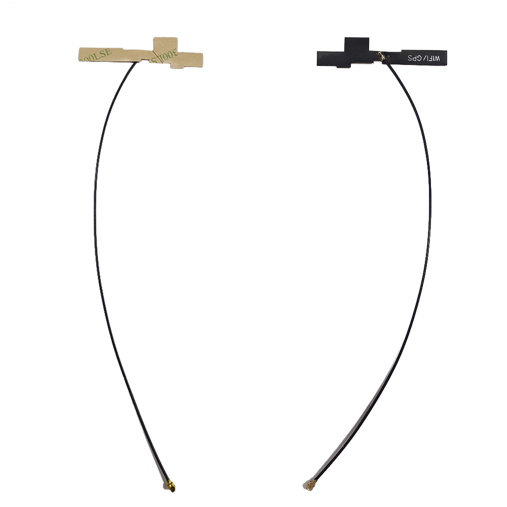


Internal GNSS antennas are integral components in modern GPS modules, designed to receive satellite signals directly within the device enclosure without requiring an external antenna. As consumer electronics and embedded systems become increasingly compact and aesthetically driven, the demand for internal antennas has surged. These antennas are typically embedded on or near the printed circuit board (PCB) of a GPS module, enabling seamless integration into smartphones, wearables, IoT devices, automotive infotainment systems, asset trackers, and portable navigation units.
Unlike external antennas—such as magnetic or whip antennas used in surveying equipment or vehicle roof mounts—internal GNSS antennas must operate efficiently within tight spatial constraints and in close proximity to other electronic components that can interfere with signal reception. Despite these challenges, they offer significant advantages in terms of form factor, durability, and user experience. Their integration eliminates the need for connectors, cables, or protruding parts, resulting in sleeker, more robust designs that are less prone to mechanical damage or water ingress.
An internal GNSS antenna for a GPS module is engineered to receive L-band signals from global navigation satellite systems, primarily focusing on the GPS L1 frequency at 1575.42 MHz, though many modern variants also support additional bands such as L2 (1227.60 MHz) and L5 (1176.45 MHz) for improved accuracy. They are often designed to be multi-constellation compatible, allowing reception from GLONASS, Galileo, and BeiDou satellites as well, thereby increasing satellite visibility and positioning reliability.
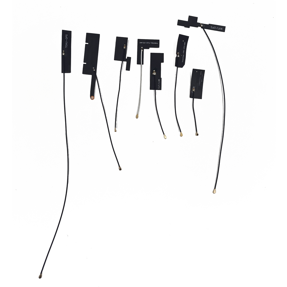
These antennas are typically of the patch, planar inverted-F (PIFA), or ceramic chip type. Ceramic chip antennas are especially popular due to their small size, high efficiency, and ease of surface-mount assembly. They consist of a high-permittivity dielectric material doped with metal elements that form a resonant structure tuned to GNSS frequencies. The compact nature of these chips allows them to fit into space-limited applications while maintaining acceptable gain and radiation patterns.
A critical aspect of internal GNSS antenna design is its dependence on the host PCB’s ground plane. Unlike external antennas that may have dedicated ground structures, internal antennas rely heavily on the device’s main ground plane for proper radiation characteristics. Therefore, optimal performance requires careful attention to layout, including sufficient ground plane area, avoidance of nearby noise sources (e.g., processors, power supplies, RF transceivers), and adherence to manufacturer-recommended keep-out zones.
Moreover, internal GNSS antennas are often paired with low-noise amplifiers (LNAs), filters, and impedance matching circuits either integrated within the antenna package or placed on the PCB. This front-end conditioning ensures that weak satellite signals—often below -130 dBm—are amplified and filtered before reaching the GNSS receiver IC, minimizing degradation from noise and interference.
The rise of high-precision applications, such as drone navigation, fleet tracking, and emergency location services, has further driven innovation in internal antenna technology. Manufacturers now offer enhanced-performance internal antennas with better axial ratio, wider bandwidth, and improved multipath rejection to meet the demands of real-time, accurate positioning.
In summary, internal GNSS antennas for GPS modules represent a crucial advancement in miniaturized navigation technology. By balancing performance, size, and integration complexity, they enable GPS functionality in a vast array of compact, mass-market devices, making satellite-based positioning ubiquitous and accessible across consumer, industrial, and automotive domains.
The design and construction of internal GNSS antennas for GPS modules involve meticulous electromagnetic engineering to achieve optimal RF performance within severe physical and environmental constraints. The primary goal is to create a small, efficient radiator capable of receiving weak circularly polarized signals from GPS and other GNSS satellites, while coexisting with numerous noise-generating components on a densely packed PCB.
One of the most common types is the ceramic patch antenna, constructed from a high-dielectric constant ceramic material (e.g., barium strontium titanate) shaped into a thin rectangular or square plate. Conductive layers are deposited on the top and bottom surfaces—the top acting as the radiating element and the bottom serving as a ground plane when mounted on the PCB. The dimensions of the ceramic element are precisely calculated to resonate at the GPS L1 frequency (1575.42 MHz), with additional tuning for L5 or multi-band operation in advanced models.
Another widely used design is the Planar Inverted-F Antenna (PIFA), which consists of a flat metal trace on the PCB or a separate flexible substrate. It features a radiating patch connected to ground via a shorting pin and fed by a coaxial or microstrip line at an offset point to achieve impedance matching. PIFAs are cost-effective and easily integrated into existing PCB layouts, though they generally offer lower efficiency compared to ceramic antennas.
More recently, LTCC (Low-Temperature Co-fired Ceramic) and embedded antennas fabricated within the PCB stack-up have gained traction. These allow even greater miniaturization and protection from environmental factors, although they require specialized manufacturing processes and simulation tools for optimization.
Regardless of type, all internal GNSS antennas must be carefully matched to a 50-ohm transmission line using passive components like inductors and capacitors. Impedance mismatch leads to signal reflection and loss, degrading sensitivity. Matching networks are often fine-tuned using vector network analyzer (VNA) measurements during prototyping.
Integration with supporting electronics is essential. Most internal antennas are used in conjunction with a Low-Noise Amplifier (LNA) placed within 5–10 mm of the antenna feed point to minimize trace losses. Bandpass filters may also be included to suppress interference from nearby wireless systems such as Wi-Fi (2.4/5 GHz), Bluetooth, and cellular bands (LTE, 5G). Some advanced modules integrate the LNA, filter, and matching network into a single shielded package with the antenna, forming a complete "antenna-in-package" solution.
Thermal stability and mechanical robustness are also key considerations. The antenna must maintain performance across operating temperatures (-40°C to +85°C) and survive reflow soldering during assembly. Encapsulation in protective resin or metal shielding helps prevent detuning due to humidity or physical stress.
Finally, placement on the host PCB is critical. The antenna should be located at the edge of the board, away from large metal objects, batteries, displays, and high-speed digital lines. A continuous ground plane of adequate size (typically ≥30x30 mm) beneath the antenna is necessary for proper radiation. Simulation tools like ANSYS HFSS or CST Studio Suite are used extensively to model radiation patterns, efficiency, and SAR (Specific Absorption Rate) before final production.
In essence, the construction of internal GNSS antennas blends materials science, RF design, and system-level integration to deliver reliable satellite signal reception in the smallest possible footprint.Working Principles of Internal GNSS Antennas for GPS Modules
Internal GNSS antennas for GPS modules operate based on the fundamental principles of electromagnetic wave reception, resonance, and signal conditioning tailored to the specific characteristics of satellite navigation signals. Their primary function is to capture extremely weak radio frequency (RF) signals transmitted by orbiting GNSS satellites—typically in the range of -130 dBm to -160 dBM—and deliver them to the GNSS receiver IC with minimal degradation.
GNSS satellites, including those in the GPS constellation, transmit right-hand circularly polarized (RHCP) L-band signals. This polarization ensures that signals maintain consistent orientation as they travel through the ionosphere and reflect off surfaces. An internal antenna must be designed to efficiently receive RHCP waves, which requires a radiating structure capable of generating or responding to rotating electric fields. Patch-type ceramic antennas achieve this through their geometry and excitation method, often using dual-feed points or asymmetric coupling to induce the necessary phase shift between orthogonal modes.
The most commonly used frequency is GPS L1 at 1575.42 MHz, which carries the Coarse/Acquisition (C/A) code for civilian use and the encrypted P(Y) code for military applications. Modern high-performance internal antennas also support L2C (1227.60 MHz) and especially L5 (1176.45 MHz), introduced for safety-of-life applications such as aviation and autonomous driving. The L5 band offers higher transmission power, wider bandwidth (10 MHz), and advanced modulation (QPSK), enabling better multipath resistance and faster signal acquisition.
When a GNSS satellite transmits its signal, it travels approximately 20,000 km to Earth, undergoing atmospheric delays, Doppler shifts due to relative motion, and potential obstructions from buildings, trees, or terrain. Upon reaching the device, the internal antenna captures these signals via electromagnetic induction. The incident RF energy induces a small alternating current in the conductive elements of the antenna, proportional to the strength and polarization match of the incoming wave.
Because the received signal is so weak, immediate amplification is critical. A Low-Noise Amplifier (LNA) is placed as close as possible to the antenna feed point to boost the signal before noise from PCB traces or surrounding circuits can corrupt it. The LNA increases the signal level while adding minimal internal noise, preserving the signal-to-noise ratio (SNR)—a key factor in achieving fast Time-to-First-Fix (TTFF) and accurate positioning.
Following amplification, the signal usually passes through a bandpass filter tuned to the GNSS frequency band (e.g., 1560–1590 MHz for L1). This filter rejects out-of-band interference from nearby transmitters such as cellular base stations, Wi-Fi routers, Bluetooth devices, and digital processors, all of which can desensitize the receiver if not properly suppressed.
Impedance matching is another crucial aspect of operation. The antenna’s output impedance must closely match the 50-ohm input impedance of the RF chain to minimize reflections and maximize power transfer. Mismatches cause standing waves and signal loss, reducing sensitivity. Matching networks composed of surface-mount inductors and capacitors are typically employed to fine-tune performance across temperature and manufacturing variations.
Once conditioned, the RF signal is down-converted to an intermediate frequency (IF) or directly sampled in a zero-IF architecture by the GNSS baseband processor. Using precise timing models and ephemeris data, the receiver calculates the time delay of each satellite’s signal, computes pseudoranges, and solves for position, velocity, and time (PVT).
Advanced techniques like Real-Time Kinematic (RTK) and Precise Point Positioning (PPP) further enhance accuracy by correcting ionospheric delays, clock errors, and orbital inaccuracies using augmentation data from ground-based or satellite-based correction services. For these methods to work effectively, the internal antenna must provide stable, low-multipath signal reception—a challenge addressed through optimized radiation patterns and grounding.
In dynamic environments, the antenna may experience blockage due to hand grip (in smartphones), vehicle roofs, or indoor shielding. To mitigate this, some systems employ antenna diversity—using multiple internal antennas or switching between internal and external options—or integrate sensor fusion with IMUs to maintain position during signal outages.
Thus, the working principle of an internal GNSS antenna is not merely passive reception but part of an active, multi-stage signal acquisition and processing system designed to extract usable location data from some of the weakest detectable RF signals in modern communications.
Internal GNSS antennas offer several compelling advantages that make them indispensable in today’s compact electronic devices, but they also come with inherent trade-offs and technical challenges.
Advantages:
Compact Size and Seamless Integration: The most significant advantage is their small footprint. Ceramic chip and PIFA designs occupy only a few square millimeters, allowing integration into slim smartphones, smartwatches, fitness trackers, and IoT sensors where space is at a premium.
Improved Aesthetics and Durability: Without external connectors or protruding elements, devices appear sleeker and are more resistant to physical damage, dust, and moisture. This enhances reliability in consumer and industrial applications alike.
Cost-Effective Mass Production: Surface-mount technology enables automated assembly alongside other components, reducing labor costs and improving yield consistency. Integrated front-end modules further simplify design and reduce bill-of-materials complexity.
Ease of Design Reuse: Once validated, an internal antenna layout can be reused across product lines, accelerating time-to-market for new devices.
User Convenience: Eliminates the need for users to attach or align external antennas, making GNSS functionality truly plug-and-play.
Challenges:
Reduced Efficiency and Gain: Due to size constraints and proximity to lossy materials (batteries, displays, metal casings), internal antennas typically exhibit lower radiation efficiency (often 30–60%) compared to external counterparts (>70%). This impacts sensitivity and time-to-first-fix.
Susceptibility to Interference: Located near noisy digital circuits, internal antennas are vulnerable to electromagnetic interference (EMI) from processors, switching regulators, and high-speed interfaces like USB or MIPI.
Ground Plane Dependency: Performance heavily relies on the host PCB’s ground plane size and layout. Inadequate grounding leads to poor radiation patterns, reduced gain, and detuning.
Detuning from Environmental Factors: Nearby objects—such as human hands, batteries, or enclosures—can alter the antenna’s resonant frequency and impedance, requiring robust matching networks or adaptive tuning circuits.
Thermal and Mechanical Stress: During reflow soldering or under thermal cycling, material expansion can shift resonance, necessitating careful selection of thermally stable substrates and adhesives.
Limited Bandwidth and Multi-Band Complexity: Achieving wideband or multi-band operation (L1 + L5) in a tiny form factor is challenging and often results in compromised performance on one band.
Despite these challenges, ongoing advancements in antenna miniaturization, filtering, and system co-design continue to narrow the performance gap between internal and external solutions, making internal GNSS antennas increasingly viable even for high-accuracy applications.
Internal GNSS antennas have become a cornerstone technology in the proliferation of location-aware devices across consumer, industrial, automotive, and healthcare sectors. Their ability to deliver reliable positioning within compact, aesthetically pleasing form factors has enabled widespread adoption in applications where external antennas are impractical or undesirable.
One of the most prominent applications is in smartphones and wearable devices. Modern smartphones integrate internal GNSS antennas to support navigation apps, fitness tracking, augmented reality (AR), geotagging, and emergency services such as Emergency SOS via satellite. With the introduction of dual-frequency (L1 + L5) GNSS receivers in flagship models like the iPhone 14 and newer Android devices, internal ceramic chip antennas have evolved to support higher bandwidth and improved multipath rejection, enabling sub-meter accuracy even in urban environments. Wearables like smartwatches and fitness bands also rely on ultra-compact internal antennas for real-time route mapping during running, cycling, or hiking.
In the Internet of Things (IoT) domain, internal GNSS antennas are essential for asset tracking, fleet management, and logistics monitoring. Compact trackers embedded in shipping containers, pallets, or high-value equipment use internal antennas to provide continuous location updates without compromising device durability or battery life. These solutions often combine GNSS with low-power wide-area networks (LPWAN) like LoRaWAN or NB-IoT, where the antenna must coexist with multiple RF systems on a single PCB.
The automotive industry increasingly relies on internal GNSS antennas for telematics, stolen vehicle recovery, and advanced driver-assistance systems (ADAS). While high-end autonomous vehicles may use external roof-mounted antennas for centimeter-level precision, many mid-tier infotainment and navigation systems utilize internal modules integrated into dashboard control units. As vehicles adopt more electronic features, minimizing connector count and improving water/dust resistance through internal designs becomes critical.
Drones and unmanned aerial vehicles (UAVs) also benefit from internal GNSS antennas for stable flight control, return-to-home functions, and automated mission execution. Given strict size and weight constraints, UAV manufacturers prefer surface-mount ceramic antennas that offer sufficient performance while allowing streamlined aerodynamic designs.
Other notable applications include portable medical devices, such as GPS-enabled emergency response tags for elderly patients, and smart city infrastructure, including parking sensors, environmental monitors, and public transit trackers. In agriculture, compact GNSS modules with internal antennas are used in handheld field mapping tools and small-scale robotic harvesters.
Looking ahead, several future trends will shape the evolution of internal GNSS antennas:
Multi-Band and Multi-Constellation Integration: As GPS modernizes and new signals like L6 and BeiDou B2b emerge, internal antennas will need to support broader frequency coverage while maintaining small size and efficiency.
AI-Driven Signal Optimization: Machine learning algorithms will be used to predict signal degradation, classify interference sources, and dynamically adjust filtering or beamforming parameters in software-defined radio architectures.
Integrated Antenna Modules: We are seeing a rise in "antenna-in-package" (AiP) solutions that combine the radiating element, LNA, filter, and matching network into a single shielded module, reducing design complexity and improving consistency.
Hybrid Positioning Systems: Internal GNSS antennas will increasingly work in tandem with 5G/6G positioning, Wi-Fi RTT, Bluetooth AoA, and inertial sensors to enable seamless indoor-outdoor navigation.
Advanced Materials and Manufacturing: The use of metamaterials, photonic crystals, and additive manufacturing techniques could lead to thinner, more efficient antennas with enhanced directivity and reduced sensitivity to nearby components.
Energy Efficiency Improvements: Ultra-low-power GNSS modes and duty-cycling techniques will allow internal antennas to function longer on small batteries, crucial for IoT edge devices.
Security Enhancements: With rising concerns about spoofing and jamming, future internal antennas may incorporate polarization discrimination or spatial filtering to detect and reject fake signals.
As demand grows for smarter, smaller, and more connected devices, internal GNSS antennas will continue to evolve—balancing performance, integration, and cost—to remain at the heart of next-generation location technologies.
Conclusion
Internal GNSS antennas for GPS modules represent a pivotal advancement in the democratization of precise positioning technology. By enabling satellite navigation functionality within the tight confines of modern electronics, they have made location awareness ubiquitous—from everyday smartphones to critical industrial and safety systems. Their success lies in the harmonious integration of RF engineering, materials science, and system-level design, allowing weak GNSS signals to be captured, amplified, and processed despite severe physical and electromagnetic challenges.
While inherently limited by size and proximity to noise sources, ongoing innovations in antenna topology, front-end circuitry, and multi-sensor fusion are steadily overcoming these barriers. Ceramic chip antennas, PIFAs, and embedded solutions now deliver performance that was once exclusive to bulky external units, supporting dual-frequency operation, fast time-to-first-fix, and robust signal tracking in complex urban environments.
The diverse range of applications—from consumer wearables and IoT trackers to automotive telematics and drone navigation—underscores their transformative impact. As industries move toward automation, connectivity, and real-time decision-making, the role of internal GNSS antennas will only grow in importance.
Future developments will focus on tighter integration, intelligent signal processing, energy efficiency, and resilience against interference and cyber threats. With the convergence of 5G, AI, and low Earth orbit (LEO) satellite networks, internal GNSS antennas will evolve into smarter, more adaptive components capable of delivering accurate positioning anywhere on Earth.
In conclusion, internal GNSS antennas are not merely passive components but active enablers of a globally connected, location-intelligent world. As technology continues to shrink and smart devices become ever more pervasive, these tiny yet powerful antennas will remain at the forefront of innovation, silently guiding us through an increasingly data-driven future.

 86 0755 2819 9597
Lucy Yang | lucy.y@toxutech.com
Nicole Li | nicole@toxutech.com
Dotty Zhao | sales04@toxutech.com
Global Business Director / Sales Team / Global Operations


 En
En Cn
Cn Korean
 Home >


