

-
Products -PCBA Manufacturing RF Connectors RF Cable Assemblys Embedded Antennas External Antennas Positioning Chips and Modules
RF Connectors

RF Cable Assemblys
Embedded Antennas
External Antennas
Positioning Chips and Modules


 Language


Language


In an age defined by seamless connectivity and ubiquitous location-aware technology, the ability of a device to precisely know its location and maintain a robust, high-speed data connection is paramount. This capability is the synergistic product of two fundamental wireless technologies: the Global Positioning System (GPS) for satellite-based navigation and Wi-Fi for local area networking. While often designed and discussed separately, the integration of these two functions into a single antenna solution represents a critical engineering advancement for a vast array of modern applications. The high-sensitivity dual-band WiFi GPS antenna is a specialized component designed to provide superior performance for both functions simultaneously, overcoming the significant challenges of co-location and interference.
This antenna's name reveals its core characteristics:
High-Sensitivity: This attribute is primarily targeted at the GPS functionality. GPS signals travel over 20,000 kilometers from medium-Earth orbit and are incredibly weak by the time they reach a receiver on the ground, often compared to the light from a dim lightbulb viewed from thousands of miles away. High-sensitivity refers to the antenna's ability to capture these exceedingly faint signals efficiently, even in challenging environments like urban canyons, under dense tree cover, or inside vehicles where signal strength is severely degraded. This is achieved through specialized design, low-loss materials, and often an integrated Low-Noise Amplifier (LNA).
Dual-Band: This term applies to the Wi-Fi portion of the antenna. Modern Wi-Fi operates primarily in two frequency bands: the 2.4 GHz band (IEEE 802.11b/g/n/ax) and the 5 GHz band (IEEE 802.11a/n/ac/ax). A dual-band Wi-Fi antenna is engineered to operate efficiently across both these bands, providing compatibility with all modern Wi-Fi routers and access points. This allows devices to leverage the longer range and better wall-penetration of 2.4 GHz or the higher data rates and reduced interference of the cleaner 5 GHz spectrum.
WiFi GPS Antenna: This denotes the combination of two distinct radiating elements (or a single, cleverly designed element) within one unit, tailored to operate at the specific frequencies for Wi-Fi (2.4 GHz & 5 GHz) and GPS (1.575 GHz).
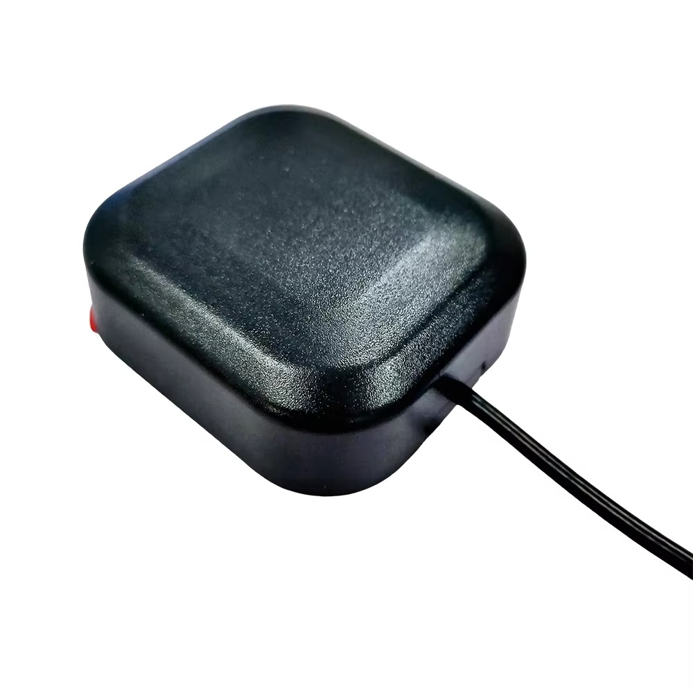
The primary driver for this combo antenna is spatial and design efficiency. Instead of requiring two separate antennas with their own cables, connectors, and allocated PCB space, a single integrated unit simplifies product design, reduces assembly costs, and allows for more compact and aesthetically pleasing devices. From in-car infotainment systems and drones to portable IoT gateways and precision agricultural equipment, this antenna provides the essential wireless link for both data communication and pinpoint positioning, forming the backbone of the connected intelligent device ecosystem.
The design and construction of a high-sensitivity dual-band WiFi GPS antenna is a complex exercise in electromagnetic engineering, requiring careful attention to isolation, efficiency, and physical form factor. It is a system designed to manage coexistence between a highly sensitive receiver and a powerful transmitter.
1. Radiating Elements and Architecture:
There are two predominant architectural approaches:
Co-located Separate Elements: This design features two distinct antenna elements housed within a single enclosure. A dedicated GPS patch antenna, typically based on a ceramic substrate to achieve a small form factor at the 1.575 GHz frequency, is positioned alongside a dual-band Wi-Fi antenna. The Wi-Fi antenna is often a printed inverted-F antenna (PIFA) or a monopole design, carefully meandered and tuned to resonate at both 2.4 GHz and 5 GHz. The physical separation and orientation of these elements are critical to minimize coupling and interference.
Shared-Aperture/Single Element Design: A more advanced and integrated approach involves designing a single radiating structure that can operate at all three frequency bands (GPS ~1.575 GHz, Wi-Fi 2.4 GHz, Wi-Fi 5 GHz). This is achieved through sophisticated techniques like slot-loading, parasitic elements, and multi-resonant circuits. While more compact, this design is extremely challenging as it requires impeccable isolation between the ports to prevent Wi-Fi transmit energy from completely overwhelming the GPS receiver.
2. The Pursuit of High Sensitivity:
High sensitivity for GPS is engineered through several key design choices:
Efficient Radiating Element: The GPS element is designed for maximum gain towards the zenith (the sky) and a circularly polarized radiation pattern to match the polarization of GPS satellite signals, minimizing polarization loss.
Low-Loss Materials: The use of ceramic substrates with high dielectric constants for the GPS patch and low-loss PCB materials like Rogers laminates for the Wi-Fi elements reduces dielectric losses, ensuring more of the captured signal energy is delivered to the receiver.
Integrated Low-Noise Amplifier (LNA): This is the most crucial component for achieving high sensitivity. A high-gain, low-noise-figure LNA is often embedded directly into the antenna housing or placed immediately at the GPS antenna's feed point. It provides significant amplification (e.g., 26-30 dB) to the incredibly weak GPS signals before they travel through the lossy coaxial cable to the receiver, effectively overcoming the cable's attenuation and improving the overall signal-to-noise ratio (SNR).
3. Ground Plane and PCB Integration:
Like all antennas, performance is heavily dependent on the ground plane. The antenna's datasheet will provide strict guidelines for the size and shape of the PCB ground plane beneath and around it. A sufficient ground plane is essential for achieving the desired radiation pattern, bandwidth, and efficiency. The placement of the antenna on the PCB is also critical; it must be located at the edge of the board, away from noisy digital components like processors and memory, which can radiate noise and degrade the sensitive GPS reception.
4. Isolation and Shielding:
The paramount challenge is isolating the GPS receiver from the powerful Wi-Fi transmitter. When the Wi-Fi radio transmits, it can emit energy that drowns out the faint GPS signals. Designers employ several techniques:
Physical Separation: Maximizing the distance between the GPS and Wi-Fi radiating elements within the enclosure.
Band-Pass Filters: Placing a surface-acoustic-wave (SAW) or ceramic band-pass filter on the GPS feed line. This filter allows the 1.575 GHz GPS signals to pass through but strongly attenuates the 2.4 GHz and 5 GHz Wi-Fi signals, acting as a barrier against interference.
Electromagnetic Shielding: Using metal cans or shielded compartments over sensitive sections of the PCB to contain Wi-Fi RF energy and prevent it from coupling into the GPS feed line or the receiver IC.
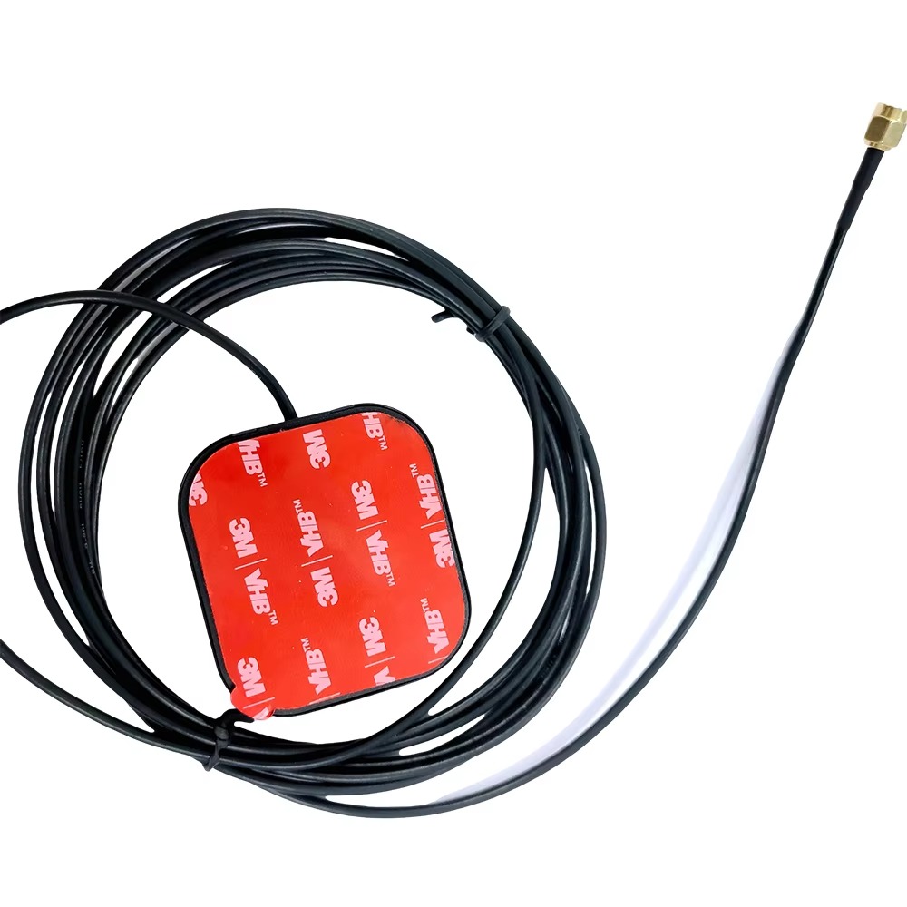
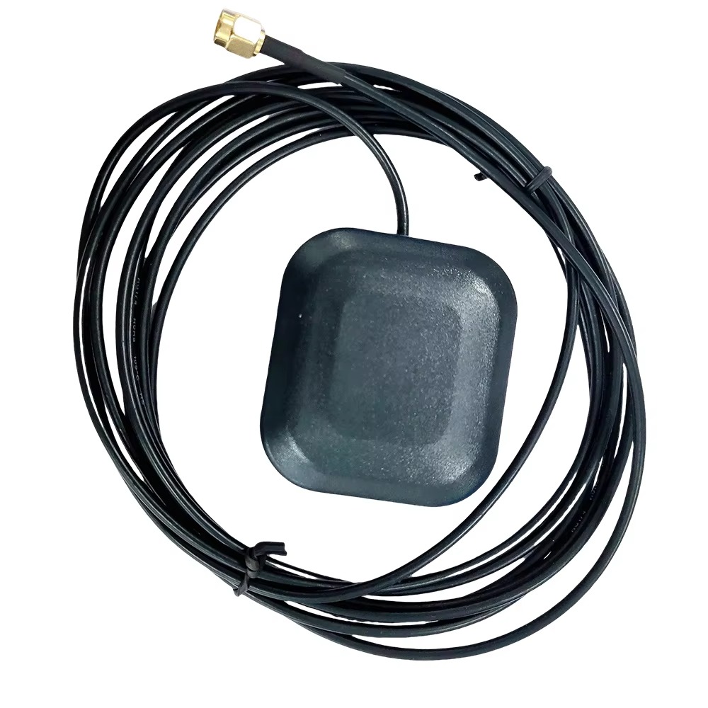
5. Connectorization:
The antenna typically features two separate coaxial output cables, each with a standard connector like an IPEX/U.FL or SMA. The cables are often different lengths to facilitate routing on a PCB. The GPS line will include a wire to supply DC power to the integrated LNA (via a bias-tee circuit in the receiver).
The working principle of this combo antenna involves managing two fundamentally different RF operations: the passive, ultra-sensitive reception of GPS signals and the active, powerful transmission and reception of Wi-Fi data packets.
1. GPS Reception - The Downlink-Only Path:
Signal Capture: GPS satellites broadcast spread-spectrum signals on the L1 frequency (1575.42 MHz). These faint, right-hand circularly polarized (RHCP) electromagnetic waves travel through space and are captured by the GPS antenna element.
Polarization and Pattern Matching: The antenna's circular polarization and hemispherical pattern ensure maximum energy is collected from satellites across the sky while rejecting reflected (multipath) signals that can have reversed polarization.
Immediate Amplification: The critically weak induced current is immediately amplified by the integrated LNA. This first-stage amplification is vital because it boosts the signal above the inherent noise floor of the subsequent coaxial cable and the receiver itself.
Filtering and Delivery: The amplified signal travels down the coaxial cable. A band-pass filter along this path ensures that out-of-band noise and interference (especially from the Wi-Fi radios) are rejected. The clean, amplified signal is then delivered to the GPS receiver IC, which performs the correlation and calculations to determine precise timing and location.
2. Wi-Fi Operation - The Transmit/Receive Path:
Wi-Fi operates in a half-duplex manner (transmits and receives, but not at the exact same time).
Transmission (Uplink): When the device needs to send data, the Wi-Fi modem/IC generates an RF signal modulated with the data. This signal is amplified by a power amplifier (PA) and sent up the coaxial cable to the dual-band Wi-Fi antenna element. The antenna converts this electrical energy into electromagnetic waves radiated out towards the access point. The antenna must efficiently handle the power output (often up to 200mW or more) across both bands.
Reception (Downlink): When data is sent from the access point, the process reverses. The Wi-Fi antenna captures the incoming waves, converts them into an electrical current, and sends this weak signal down the cable to a low-noise amplifier in the Wi-Fi receiver chain.
3. The Coexistence Mechanism:
The system's intelligence lies in managing the conflict between the powerful Wi-Fi transmit bursts and the sensitive GPS reception. This is handled by:
Hardware Filtering: The GPS band-pass filter is the primary defense, blocking Wi-Fi energy from entering the GPS receiver.
Time-Domain Duplexing (TDD) Awareness: Wi-Fi's inherent half-duplex nature means it is not transmitting 100% of the time. The receiver can be designed to be most active during gaps in Wi-Fi transmission, though this is less common than relying on robust hardware filtering.
Frequency Separation: The ~800 MHz separation between GPS L1 (1.5 GHz) and Wi-Fi 2.4 GHz (2.4 GHz) provides natural isolation that makes filtering feasible, though the 5 GHz band is farther away and easier to filter out.
Advantages:
Space and Cost Efficiency: Integrates two critical RF functions into a single mechanical unit, saving space on the PCB and reducing the bill of materials (BOM) and assembly costs associated with two separate antennas.
High Performance GPS: The dedicated focus on GPS sensitivity through specialized design and integrated LNA ensures superior location performance in weak-signal environments, which is a critical differentiator for many applications.
Simplified Product Design: Provides engineers with a pre-optimized, off-the-shelf RF solution for two key wireless features, accelerating product development cycles.
Improved Reliability: A single, housed unit with fixed cables can be more reliable than two separate antenna assemblies that are subject to cable strain and connector issues during assembly.
Aesthetics: Allows for a single, neat antenna installation point in the final product, which is important for consumer devices.
Challenges:
Electromagnetic Interference (EMI): The single greatest challenge is preventing the powerful Wi-Fi transmitter from desensitizing the GPS receiver. Despite filters, achieving perfect isolation is difficult and requires meticulous layout and shielding.
Performance Compromise: Integration often forces a trade-off. The ideal location and ground plane size for a GPS antenna (center of a large ground plane) may not be the ideal location for a Wi-Fi antenna (edge of the board for omnidirectional coverage). The final design is a compromise that may slightly sub-optimize the peak performance of each function.
Design Complexity: While it simplifies the end-product design, the antenna itself is vastly more complex to design and characterize than a single-purpose antenna. It requires extensive testing to validate performance across all bands and ensure coexistence.
Calibration: The integrated LNA has a specific gain and noise figure that must be accounted for in the system's link budget. Any variation in these components can affect performance.
Cost: While it may reduce overall system cost, the combo antenna itself is a more expensive component than a simple standalone Wi-Fi or GPS antenna due to its complexity and included active components (LNA).
Applications:
In-Vehicle Systems: Telematics units, infotainment systems, and advanced driver-assistance systems (ADAS) that require continuous location tracking and Wi-Fi hotspot functionality.
Drones and UAVs: For precise navigation (GPS) and First-Person View (FPV) video transmission or telemetry downlink (Wi-Fi).
Portable Navigation Devices and Rugged Tablets: Used by first responders, surveyors, and in logistics for mapping and data communication in the field.
IoT Gateways: Devices that aggregate data from multiple sensors and need both a location stamp and a backhaul connection to the cloud via Wi-Fi.
Smart Cameras: Security and action cameras that geotag photos and videos and need to transfer large files wirelessly.
Future Trends:
Integration of More Technologies: The next evolution is the addition of cellular (4G/5G) and Bluetooth into the same module, creating a unified "connectivity antenna" for all wireless services.
Multi-Constellation Support: Future GPS elements will be designed for even higher sensitivity to support all GNSS constellations (Galileo, BeiDou, GLONASS) and multi-band GNSS (L1 + L5) for centimeter-level accuracy, requiring even better isolation from Wi-Fi.
Active Interference Cancellation: Advanced systems may employ active electronic techniques to sample the Wi-Fi transmit noise and generate a cancelling signal to nullify it in the GPS receiver path.
Beamforming for Wi-Fi: To support Wi-Fi 6 and Wi-Fi 7, future combo antennas may incorporate multiple Wi-Fi elements to form phased arrays capable of beamforming, directing signal energy towards the client device for improved speed and range.
Enhanced Filtering Technologies: Development of more selective, lower-loss filters (e.g., using BAW or FBAR technology) will be key to improving isolation without degrading the desired signals.
Conclusion
The high-sensitivity dual-band WiFi GPS antenna is a quintessential example of engineering innovation driven by market need. It represents the successful fusion of two disparate wireless technologies into a single, high-performance, and commercially viable component. By solving the profound challenge of coexisting a whisper-sensitive receiver with a powerful transmitter, it enables a generation of devices that are both precisely located and continuously connected.
While it introduces design complexities and requires careful system integration, its advantages in space savings, cost reduction, and performance reliability make it an indispensable solution across automotive, consumer, and industrial domains. As the demand for connectivity and location accuracy continues to grow, with trends like autonomous machines and the IoT expanding rapidly, the role of this integrated antenna will only become more critical. It is not merely a component but a strategic enabler, forming the essential wireless bridge between a device's physical presence in the world and its digital identity in the cloud. The ongoing evolution of this technology will continue to push the boundaries of what is possible in miniaturized, multifunctional wireless design.

 86 0755 2819 9597
Lucy Yang | lucy.y@toxutech.com
Nicole Li | nicole@toxutech.com
Dotty Zhao | sales04@toxutech.com
Global Business Director / Sales Team / Global Operations


 En
En Cn
Cn Korean
 Home >


