

-
Products -PCBA Manufacturing RF Connectors RF Cable Assemblys Embedded Antennas External Antennas Positioning Chips and Modules
RF Connectors

RF Cable Assemblys
Embedded Antennas
External Antennas
Positioning Chips and Modules


 Language


Language


In an increasingly connected and location-aware world, the demand for reliable Global Positioning System (GPS) functionality has moved beyond open-sky environments to the most challenging signal conditions imaginable. From the deep urban canyons of megacities to the dense foliage of forests and the interior of buildings, the need to know one's position is ever-present. Meeting this demand requires more than a standard GPS antenna; it necessitates a high-sensitivity built-in GPS ceramic antenna. This specialized component is the product of decades of innovation in microwave engineering, semiconductor technology, and systems integration, designed to acquire and track satellite signals so weak they dwell below the natural thermal noise floor of the Earth.
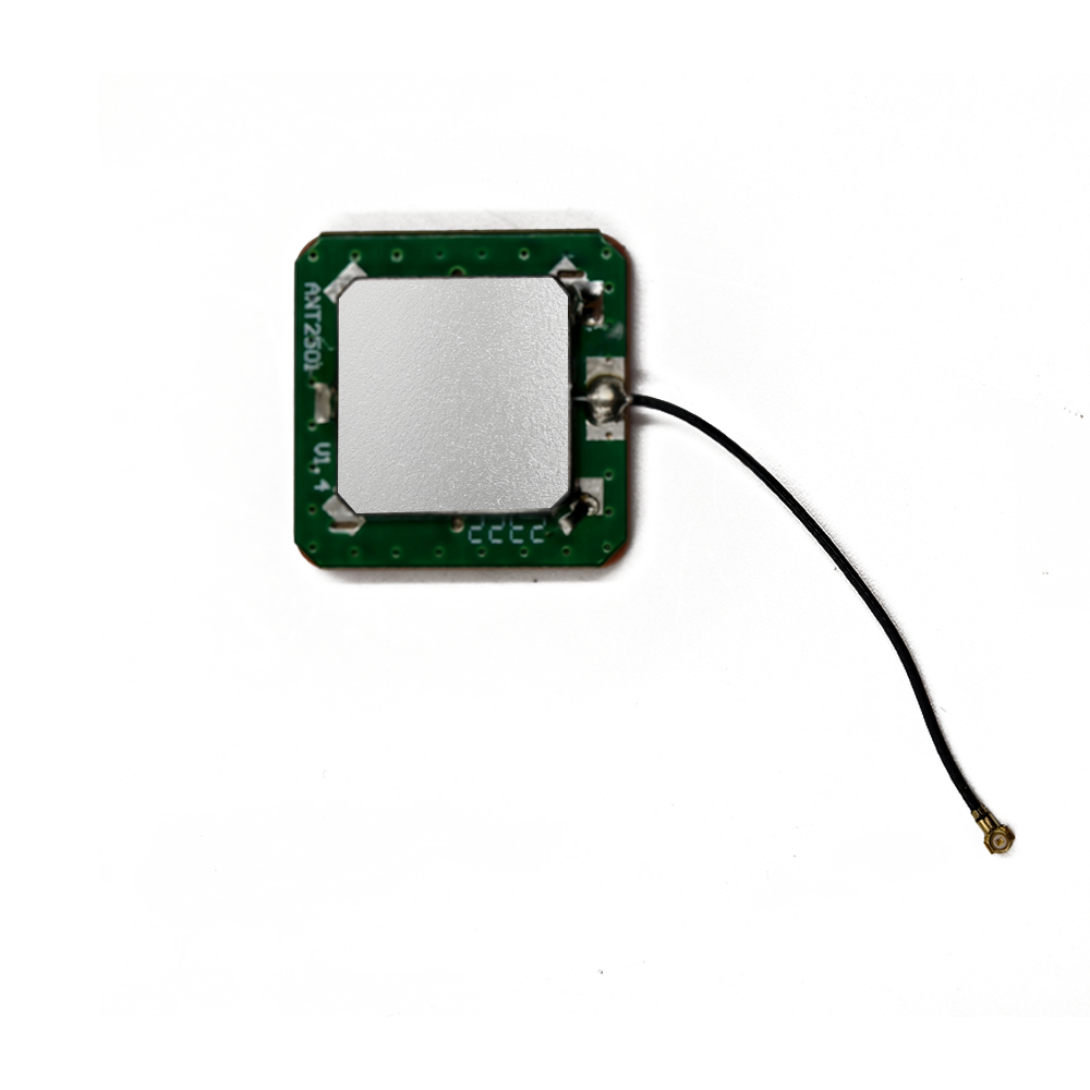
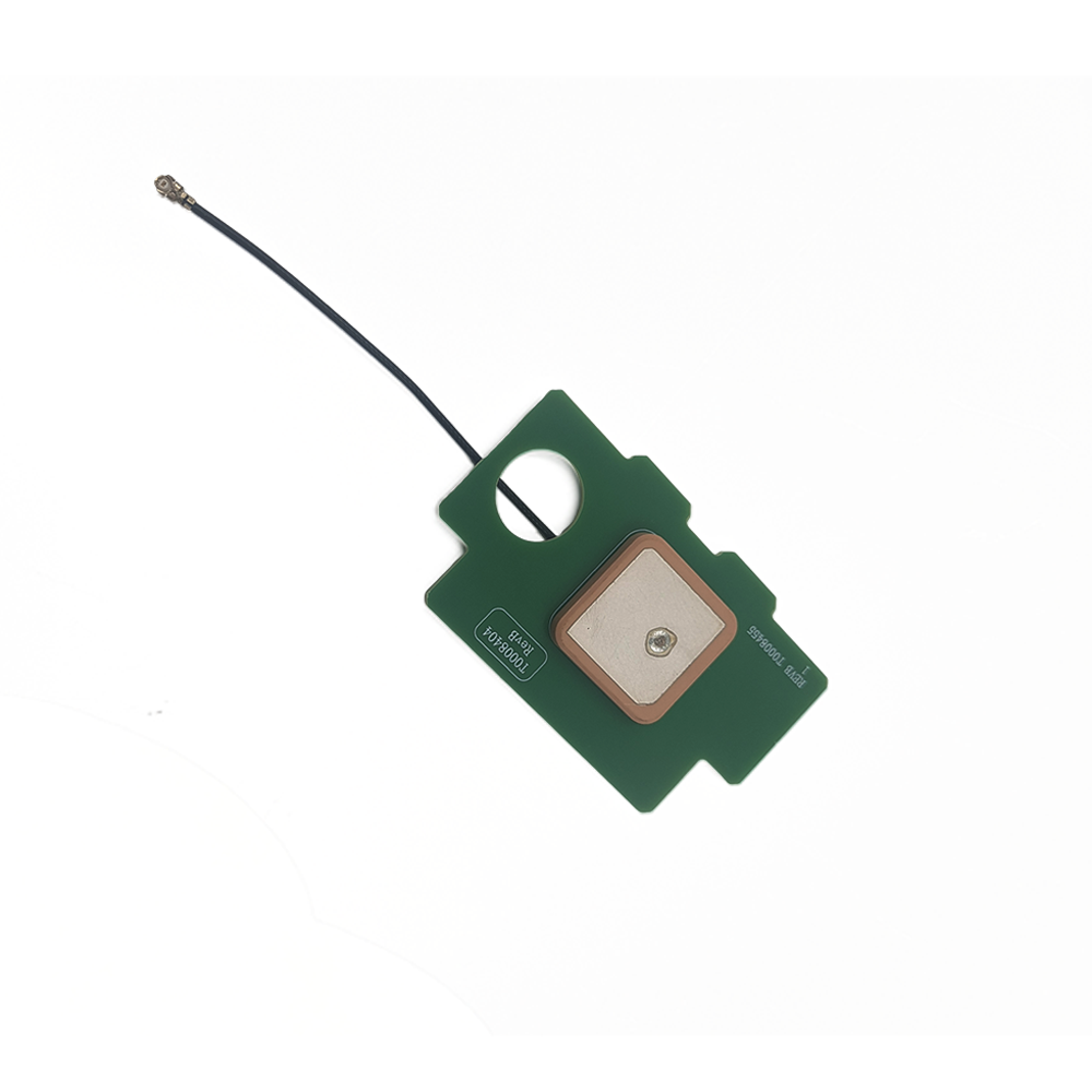
A high-sensitivity GPS antenna is fundamentally an active antenna system engineered for one primary purpose: to capture the faintest possible GPS signals and deliver a usable, amplified signal to the receiver with the utmost integrity. The term "high-sensitivity" refers not to a single specification but to a holistic system performance characteristic. It encompasses a low noise figure, high gain, exceptional linearity to handle interference, and sophisticated signal processing in the accompanying receiver. The "built-in" and "ceramic" aspects describe its physical implementation: a compact, robust, and surface-mount compatible patch antenna made from a high-dielectric ceramic substrate, integrated directly into a device's housing or printed circuit board (PCB).
The core challenge these antennas address is the incredible weakness of the GPS signal itself. Transmitted by satellites over 20,000 kilometers away, the signals arrive at the Earth's surface with a power level of approximately -125 to -130 dBm. To put this into perspective, this is billions of times weaker than the signal from a local FM radio station and, critically, is actually weaker than the inherent background thermal noise (approximately -111 dBm/Hz in a GPS bandwidth). A standard receiver cannot distinguish a signal hidden beneath the noise. Therefore, the antenna system must not only capture this signal but also amplify it sufficiently without adding significant noise, thereby raising the signal-to-noise ratio (SNR) to a level where the receiver's correlation algorithms can lock onto it.
The evolution of this technology is a story of enabling new applications. Early GPS was used in open environments for surveying, aviation, and marine navigation. The push for consumer applications—first in automotive navigation and then explosively in smartphones and wearables—drove the need for miniaturization (hence the ceramic patch antenna) and improved performance in obstructed environments. This led to the integration of powerful Low-Noise Amplifiers (LNAs) directly at the antenna feed point, a critical architectural shift that defines the modern high-sensitivity active antenna module.
Today, these antennas are not just for GPS; they are typically multi-GNSS (Global Navigation Satellite System), capable of receiving signals from constellations like GLONASS, Galileo, and BeiDou. This provides more satellites to track, significantly enhancing availability and accuracy in difficult environments. Furthermore, they are no longer standalone components but are part of a complex ecosystem that includes advanced radio frequency (RF) front-end filtering, sophisticated baseband processors capable of massive parallel correlation, and aiding technologies like Assisted-GPS (A-GPS).
In summary, the high-sensitivity built-in GPS ceramic antenna is a key enabler of the ubiquitous, always-on positioning we now take for granted. It is a masterpiece of system-level design that transforms an seemingly impossible task—finding a whisper of a signal buried in noise—into a routine operation. It allows devices to see the invisible, providing a continuous link to global navigation s
The design and construction of a high-sensitivity built-in GPS ceramic antenna is a meticulous process that balances electromagnetic performance, physical constraints, and resilience to a hostile RF environment. Every material, layer, and component is optimized for one goal: maximizing the signal-to-noise ratio (SNR) of the delivered RF signal.
The Ceramic Substrate: Engineered for Efficiency
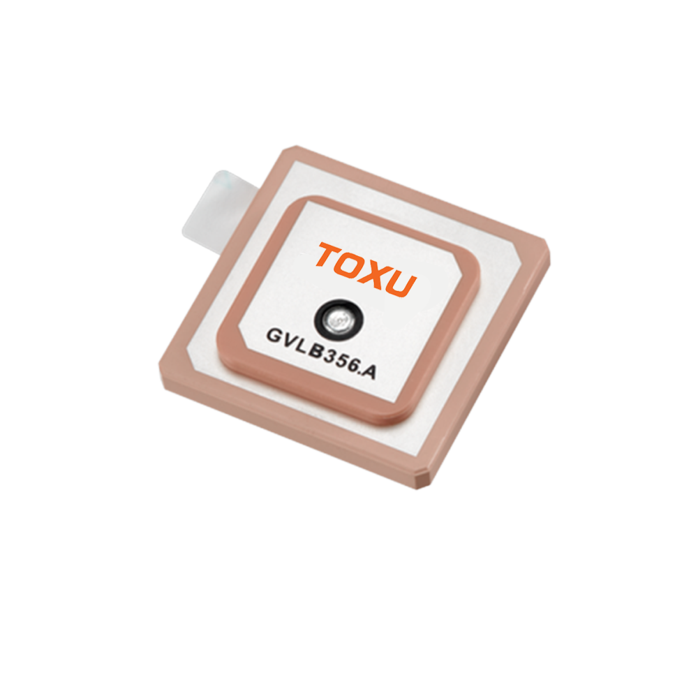
The foundation is a ceramic substrate, typically composed of materials like Barium Strontium Titanate or proprietary blends with a high dielectric constant (εr ranging from 20 to 40). This high εr is a double-edged sword: it allows for significant size reduction (as the wavelength within the material is shortened, allowing for a smaller resonant patch) but often comes with a higher loss tangent (tan δ), which attenuates the signal. For high-sensitivity applications, the choice of ceramic is a careful trade-off. Manufacturers seek materials with the highest possible εr for miniaturization while minimizing the loss tangent to preserve signal strength. The thickness of the substrate also plays a role; a thicker substrate can offer slightly wider bandwidth but may increase the overall profile.
The Radiating Patch: Precision Geometry
The radiating element is a metallic patch, usually silver or copper, precision-printed onto the ceramic surface. Its dimensions are calculated to resonate at the target frequency (1575.42 MHz for GPS L1). For multi-GNSS support covering adjacent bands (e.g., GLONASS L1, Galileo E1), the patch is designed for a wider bandwidth. This is often achieved through techniques like:
Probe Feeding: Adjusting the feed point location to excite additional modes.
Slot Cutting: Incorporating U-shaped or other slots in the patch to create multiple resonant paths.
Stacked Patches: Using two ceramic layers with patches of different sizes to cover separate frequency bands (e.g., L1 and L2/L5), though this is less common in ultra-compact consumer modules.
The Ground Plane: A Critical Shield
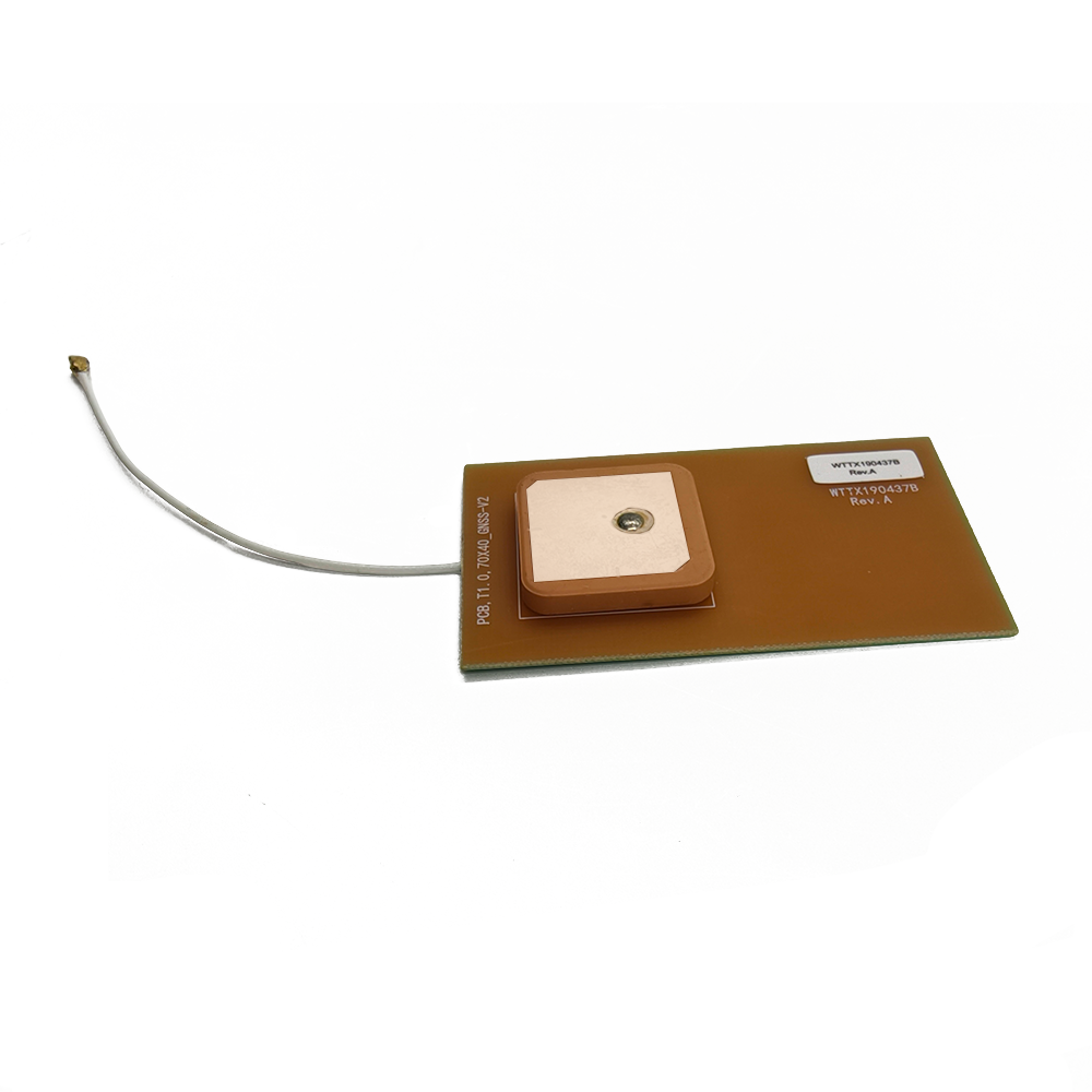
A continuous metal layer on the bottom of the ceramic substrate acts as the ground plane. This is non-negotiable for a patch antenna's operation. In a built-in design, this internal ground plane is just the beginning. The antenna's performance is heavily influenced by the size and shape of the device's main PCB, which acts as the system ground plane. A larger ground plane generally improves performance by enhancing the antenna's gain and shaping its radiation pattern more effectively towards the hemisphere. Designers must work with the product's industrial designers to allocate sufficient "keep-out" area around the antenna, free from noisy components and metal obstructions.
The Active Heart: Low-Noise Amplifier (LNA)
The single most important component for achieving high sensitivity is the LNA. It is placed electrically as close as possible to the antenna feed point—often within the antenna module itself or immediately on the PCB beneath it. This strategic placement is crucial because every centimeter of transmission line between the antenna and the first amplifier introduces loss, which directly degrades the system's noise figure. Key LNA characteristics include:
Ultra-Low Noise Figure (NF): Typically between 0.8 and 1.5 dB. This means the amplifier adds almost no inherent noise of its own to the already-weak signal.
High Gain: Usually between 15 dB and 28 dB. This amplifies the signal well above the noise floor of the subsequent receiver chip.
High Linearity (High IP3): Essential for rejecting jamming from strong nearby transmitters like cellular (4G/5G), Wi-Fi, and Bluetooth radios. A high IP3 (Third-Order Intercept Point) ensures the LNA doesn't go into compression or generate intermodulation products that could drown out the faint GPS signals.
The Filtering System: Guarding Against Interference
An integrated antenna module in a modern device operates in an electromagnetic warzone. Band-pass filters, often Surface Acoustic Wave (SAW) or Bulk Acoustic Wave (BAW) filters, are placed before and/or after the LNA. A pre-LNA filter protects the amplifier from out-of-band overload. A post-LNA filter prevents amplified broadband noise from the LNA from radiating back out through the antenna or interfering with the receiver. It also further rejects off-frequency interference.
Construction and Integration
The ceramic, patch, and ground plane are sintered into a single, robust block. The LNA and filters are then assembled onto a small PCB that is connected to the antenna feed, and the entire assembly is encapsulated in a protective plastic shield and housing. This module is designed for automatic pick-and-place machine assembly onto the host device's main PCB. The entire design process is guided by intensive 3D electromagnetic simulation (using software like CST or HFSS) to model the antenna's performance within the final product's enclosure, predicting the impact of nearby plastic, metal, and batteries.
The working principle of a high-sensitivity GPS antenna system is a battle against noise, fought at the very edge of information theory. It's a process of capturing, amplifying, and preserving a signal that is fundamentally weaker than the background static, making the invisible visible.
The Signal-in-Noise Problem
GPS satellites transmit spread-spectrum signals using a Code Division Multiple Access (CDMA) scheme. The signal is "spread" by a known Pseudo-Random Noise (PRN) code. The key to GPS reception is correlation: the receiver generates a local copy of a satellite's PRN code and slides it in time until it matches the incoming signal. A match results in a high correlation peak, allowing the receiver to calculate the time delay and thus the distance to the satellite. However, when the signal is below the noise floor, this correlation peak is buried and cannot be detected. The process is like trying to find a specific grain of sand on a beach by looking at one grain at a time; it's computationally intensive and requires time.
The Antenna and LNA: The First Line of Defense
The antenna's job is to collect as much of the available signal power as possible. The ceramic patch, with its hemispherical radiation pattern, gathers energy from satellites across the sky. The crucial first amplification step happens before any significant loss can occur. By placing an ultra-low-noise amplifier immediately at the antenna, the system amplifies both the tiny signal and the noise floor together. Critically, because the LNA adds minimal noise itself (low NF), the relative difference between the signal and the noise (the SNR) is preserved or only slightly degraded. This amplified signal-plus-noise mixture is now strong enough to be sent through a coaxial cable or PCB trace to the main receiver without being further degraded by the losses of that transmission path.
The Receiver's Role: Coherent Integration
The receiver takes this amplified signal and begins the correlation process. "High sensitivity" in the receiver is achieved primarily through long coherent integration times. The receiver can correlate the incoming signal with its local PRN code for extended periods—seconds or even tens of seconds—instead of the milliseconds used in standard reception. This extended integration effectively acts as a filter, slowly building up the correlated signal (which is coherent) while averaging out the random noise (which is non-coherent). Over time, the signal emerges from the noise. This is why a high-sensitivity GPS can take longer to get a first fix in challenging conditions; it's patiently integrating to pull the signal out of the static.
Aiding the Search: Assisted-GPS (A-GPS)
A-GPS is a powerful force multiplier for high-sensitivity systems. A standalone receiver must perform a "cold start": it must search for all possible satellites across all possible frequencies and code phases—a process that can take minutes. A-GPS, provided via a cellular or Wi-Fi connection, delivers precise time, satellite orbital data (ephemeris), and an approximate location. This information drastically narrows the search space for the receiver. It knows which satellites to look for and their approximate Doppler shift, reducing the acquisition time from minutes to seconds, even when the signals are very weak. The high-sensitivity antenna ensures that once the receiver knows where to look, it can actually see the satellites.
Multipath Mitigation
In urban environments, multipath—reflected signals—is a major source of error and can mislead the receiver's tracking loops. While not as advanced as in surveying antennas, high-sensitivity patches are designed with moderately good Right-Hand Circular Polarization (RHCP). Since GPS signals are transmitted as RHCP and many reflections reverse the polarization to LHCP, the antenna naturally attenuates some of these reflected signals, providing a basic level of multipath rejection.
In essence, the system works through a combination of pre-amplification (preserving SNR at the source), long integration (digging the signal out of the noise computationally), and aiding (narrowing the search parameters). The high-sensitivity built-in antenna is the critical first link in this chain, ensuring that the receiver has the cleanest, strongest possible signal to work with before the digital processing begins.
The integration of a high-sensitivity ceramic GPS antenna offers significant benefits for modern connected devices but also introduces a set of complex engineering challenges that must be carefully managed.
Advantages:
Superior Weak-Signal Performance: The undeniable advantage is the ability to acquire and maintain a GPS lock in environments where conventional antennas fail. This includes indoors (near windows), under dense tree cover, in urban canyons, and even in some underground parking garages. This dramatically improves the user experience by providing continuous location availability.
Rapid Time-to-First-Fix (TTFF): When combined with A-GPS data, the strong, clean signal from the active antenna allows the receiver's correlators to lock onto satellites much faster from a cold or warm start. This enables almost instantaneous positioning when opening a maps application.
Miniaturization: The use of high-dielectric ceramic substrates allows for a very small form factor (as small as 10mm x 10mm x 2mm), making it ideal for space-constrained applications like smartphones, watches, fitness trackers, and IoT sensors.
Improved System Integration and Reliability: A built-in antenna eliminates the need for external connectors and cables, which are common points of failure. The surface-mount design allows for fully automated assembly, reducing manufacturing costs and improving product robustness and waterproofing.
Enhanced Resistance to Downstream Noise: By providing high gain at the source, the amplified signal is less susceptible to degradation from the noise generated by the digital circuits on the main PCB during its journey to the receiver chip.
Challenges and Limitations:
Vulnerability to Jamming and Interference: This is the greatest challenge. The high-gain LNA that amplifies weak GPS signals is equally effective at amplifying strong, interfering signals from nearby transmitters. Cellular, Wi-Fi, Bluetooth, and even LCD display noise can desensitize the receiver, blocking GPS reception entirely. This requires sophisticated filtering and careful board layout, increasing design complexity and cost.
Power Consumption: The active LNA requires a DC bias, consuming continuous power (typically 3-10 mA). While small, this is a non-zero addition to the power budget of battery-powered devices and must be managed, often by allowing the host software to enable/disable the antenna.
Ground Plane Dependence and De-tuning: The performance of a patch antenna is heavily influenced by its surrounding environment. The device's PCB acts as its ground plane. Changes to the PCB layout, the addition of metal components, or even the user's hand gripping the device can detune the antenna, shifting its resonant frequency and degrading performance. Each product design requires extensive RF validation and often antenna re-tuning.
Thermal Management: The LNA generates heat during operation. In a tightly sealed device with no airflow, this can cause thermal drift, slightly altering its performance characteristics (gain and noise figure). In extreme cases, it can lead to reliability issues.
Cost and Complexity: An active antenna module is significantly more expensive and complex than a passive antenna. It requires additional components (LNA, filter, decoupling capacitors), a regulated power supply, and more sophisticated design and testing expertise.
Limited Dynamic Range: There's a fundamental trade-off between sensitivity and dynamic range. An amplifier optimized for ultra-low noise and high gain can be easily overloaded by very strong signals, causing compression and loss of all reception. Designers must carefully balance these parameters for the target application.
The ability to receive GPS in compromised locations has unlocked a vast array of applications that were previously impossible or unreliable, driving innovation across numerous industries.
Applications:
Smartphones and Wearables: The primary driver of volume and innovation. Enables reliable navigation, location-based services, geotagging, and fitness tracking (e.g., recording a run in a city or a hike in the woods) regardless of the environment.
Asset Tracking and Logistics: Allows for tracking of containers, pallets, and vehicles even when inside warehouses or shipping containers. Critical for supply chain management and security.
Personal Safety and Emergency Services: Wearable panic buttons, child trackers, and emergency locator beacons (e.g., PLBs) can transmit their location from indoors, drastically reducing response times. E-Call systems in cars can function after accidents in tunnels or garages.
Internet of Things (IoT): Enables location-aware IoT sensors for agriculture (monitoring fields), smart cities (monitoring infrastructure), and industrial automation (tracking tools and parts within a factory).
Automotive Telematics: Provides continuous vehicle location for usage-based insurance, fleet management, and stolen vehicle recovery, even when the vehicle is parked in a semi-enclosed structure.
Drones (UAVs): Helps maintain a stable GPS lock for navigation and position holding when flying near buildings or trees, enhancing flight safety and stability.
Future Trends:
Tighter Integration with Other Technologies: The trend is towards Integrated Passive-Active Devices (IPAD) where the antenna, LNA, filter, and even the GNSS receiver are combined into a single system-in-package (SiP) module. This saves space, simplifies design, and optimizes performance.
AI-Powered Interference Mitigation: Future systems may incorporate machine learning algorithms to identify and digitally filter or null out specific sources of interference in real-time, making GNSS reception more robust in increasingly crowded RF environments.
Multi-Band GNSS for Consumer Devices: While currently prevalent in high-precision markets, multi-band (L1+L5) GNSS is trickling down to consumer devices. This requires more complex antenna designs but offers significant advantages in accuracy and faster convergence times, even in challenging signal conditions.
Coexistence with 5G and Beyond: As 5G FR2 (mmWave) frequencies are deployed, device housings will become more metallic to act as antennas, creating Faraday cages that block GPS signals. Future antenna designs will need to be integrated into these new structures, perhaps as structurally integrated antennas or using metamaterials to allow RF transparency at GPS frequencies.
Precision for Mass Markets: The combination of multi-band GNSS, cloud-based corrections, and enhanced antennas will bring decimeter-level accuracy to consumer applications like smartphone-based AR, robotics, and vehicle-to-everything (V2X) communication.
Low-Earth Orbit (LEO) Satellite Support: Some companies are proposing hybrid GNSS/LEO positioning. Future antennas may need to support additional frequency bands to leverage signals from LEO constellations for even faster and more robust positioning indoors and underground.
Conclusion
The high-sensitivity built-in GPS ceramic antenna is a transformative technology that has been instrumental in making location services a reliable and ubiquitous utility. It represents a perfect synergy of materials science, RF engineering, and semiconductor technology, all focused on solving the profound challenge of recovering a signal buried in noise. By integrating amplification at the point of capture, it extends the reach of GNSS into the depths of the modern urban and indoor environment, empowering a new generation of applications that rely on always-available positioning.
While it introduces design challenges related to interference, power, and integration, its advantages in performance, miniaturization, and reliability have made it the undisputed solution for virtually all modern portable and IoT devices. The constant push for smaller, more efficient, and more powerful electronics ensures that innovation in this field will continue.
The future of this technology is not just about greater sensitivity but about greater intelligence and integration. As we move towards a world of autonomous systems, pervasive IoT, and immersive augmented reality, the demand for continuous, reliable, and precise positioning will only intensify. The high-sensitivity built-in antenna, though a small and often invisible component, will remain a critical enabler on this journey, serving as the essential gateway between the digital world and its physical location on Earth.

 86 0755 2819 9597
Lucy Yang | lucy.y@toxutech.com
Nicole Li | nicole@toxutech.com
Dotty Zhao | sales04@toxutech.com
Global Business Director / Sales Team / Global Operations


 En
En Cn
Cn Korean
 Home >


