

-
Products -PCBA Manufacturing RF Connectors RF Cable Assemblys Embedded Antennas External Antennas Positioning Chips and Modules
RF Connectors

RF Cable Assemblys
Embedded Antennas
External Antennas
Positioning Chips and Modules


 Language


Language


In the rapidly evolving landscape of global navigation satellite systems (GNSS), the demand for positioning solutions that can operate reliably in challenging signal environments—such as urban canyons, dense forests, indoor spaces, and remote rural areas—has never been higher. The high sensitivity active GNSS ceramic antenna emerges as a pivotal technology to meet this demand, combining the compact form factor of ceramic-based antennas with advanced active amplification and signal processing capabilities to capture even the weakest GNSS signals. Unlike standard active GNSS antennas (which may struggle in signal-scarce scenarios), high sensitivity variants are engineered to detect signals as low as -165 dBm to -170 dBm—far weaker than the -155 dBm threshold of many conventional antennas—making them indispensable for applications where positioning accuracy and reliability cannot be compromised.
To contextualize the importance of high sensitivity, it is critical to understand the limitations of traditional GNSS antennas. In urban environments, tall buildings block and reflect GNSS signals, creating "urban canyons" where only a handful of satellites are visible, and the received signals are attenuated (weakened) by 10-20 dB. In indoor spaces—such as shopping malls, airports, or warehouses—signals are further attenuated by walls, ceilings, and metal structures, often dropping below the detection limit of standard antennas. Similarly, in dense forests or remote areas with limited satellite coverage, signals are scattered by foliage or travel longer distances, resulting in extremely low signal strength. High sensitivity active GNSS ceramic antennas address these challenges by amplifying weak signals and reducing noise, ensuring that even in these harsh conditions, the antenna can provide usable positioning data.
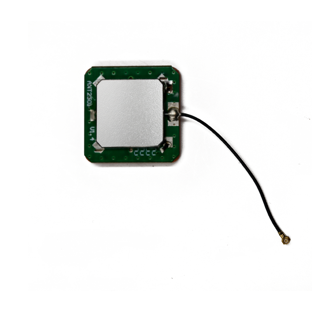
At its core, a high sensitivity active GNSS ceramic antenna integrates three key components: a ceramic antenna element (optimized for broad frequency coverage and signal capture), a low-noise amplifier (LNA) with ultra-low noise figure (typically <0.8 dB), and often a signal filter to eliminate interference from other radio frequency (RF) sources. The ceramic element, made from high-dielectric-constant (high-εr) materials like barium titanate or alumina composites, enables the antenna to be compact (typically 6mm × 6mm to 15mm × 15mm) while maintaining efficient signal reception across multiple GNSS bands (e.g., GPS L1, GLONASS G3, Galileo E1, BeiDou B1). The active components—the LNA and filter—work in tandem to boost weak signals without introducing excessive noise, a critical distinction from standard active antennas, which may have higher noise figures (1.0-1.5 dB) that obscure ultra-weak signals.
The market for high sensitivity active GNSS ceramic antennas is driven by several key trends. The growth of the Internet of Things (IoT) has led to a surge in demand for asset tracking devices that operate in diverse environments—from shipping containers stacked in ports (where metal blocks signals) to delivery drones navigating urban skies. The rise of autonomous systems, including self-driving cars and industrial robots, requires positioning solutions that can maintain accuracy even when satellite visibility is limited. Additionally, the expansion of smart cities and indoor positioning applications (such as wayfinding in airports or inventory tracking in warehouses) has created a need for antennas that can operate indoors, where standard GNSS antennas fail. According to a 2024 report by MarketsandMarkets, the global high sensitivity GNSS antenna market is projected to grow at a CAGR of 12.3% from 2024 to 2029, reaching $8.7 billion by 2029—driven primarily by demand from IoT, automotive, and aerospace sectors.
Regulatory standards also play a role in shaping these antennas. Global certifications such as FCC (U.S.), CE (EU), and IC (Canada) mandate strict limits on electromagnetic interference (EMI) and require antennas to meet performance benchmarks for signal sensitivity and reliability. For example, the FCC’s Part 15 regulations specify that GNSS antennas must not emit excessive RF noise that could interfere with other devices, while the EU’s ETSI EN 303 303 standard sets minimum sensitivity requirements for GNSS receivers in automotive applications. High sensitivity active GNSS ceramic antennas are designed to comply with these standards, ensuring their compatibility with global markets and their ability to integrate seamlessly with other electronic systems.
In summary, high sensitivity active GNSS ceramic antennas represent a critical advancement in GNSS technology, bridging the gap between compact form factors and reliable performance in weak-signal environments. Their ability to capture ultra-weak signals, combined with their small size and low power consumption, makes them essential for a wide range of applications—from IoT asset trackers to autonomous vehicles. As the demand for precise, ubiquitous positioning continues to grow, these antennas will play an increasingly vital role in enabling the next generation of connected devices and systems.
The design and construction of high sensitivity active GNSS ceramic antennas are a meticulous process that balances three core objectives: maximizing signal capture efficiency, minimizing noise introduction, and ensuring compactness for integration into space-constrained devices. Every component—from the ceramic substrate to the LNA and packaging—is engineered with these goals in mind, and even subtle design choices (such as the choice of dielectric material or LNA transistor type) can significantly impact the antenna’s sensitivity and performance. This section breaks down the key design elements, materials, and manufacturing processes that define these antennas, as well as the technical trade-offs that engineers must navigate to achieve high sensitivity.
2.1 Core Components and Their Design
A high sensitivity active GNSS ceramic antenna consists of four primary components: the ceramic antenna element, the ultra-low-noise LNA, the band-pass filter, and the matching network. Each component is optimized to contribute to the antenna’s high sensitivity, and their integration is critical to minimizing signal loss and noise.
2.1.1 Ceramic Antenna Element
The ceramic antenna element is the foundation of signal capture, responsible for receiving GNSS signals across multiple bands and converting them into electrical signals. Its design is defined by two key factors: the dielectric material and the radiator structure.
Dielectric Material: The ceramic substrate is made from high-εr materials to enable compact size while maintaining efficient signal reception. Common materials include barium titanate (BaTiO3) with an εr of 20-40, alumina (Al2O3) with an εr of 9-10, and composite materials (e.g., BaTiO3-alumina blends) with tailored εr values. High-εr materials reduce the wavelength of the GNSS signal within the ceramic, allowing the antenna to be smaller than traditional air-dielectric antennas. For example, a ceramic substrate with an εr of 30 can reduce the antenna’s size by a factor of √30 (≈5.5) compared to an air-dielectric antenna operating at the same frequency (1575.42 MHz for GPS L1). However, high-εr materials also have higher dielectric loss (tanδ), which can absorb signal energy and reduce efficiency. To mitigate this, engineers select materials with low tanδ (typically <0.001 at GNSS frequencies) to ensure minimal signal loss.
Radiator Structure: The ceramic element uses a patch radiator design— a thin, conductive patch (usually made of silver or copper) printed or sputtered onto the ceramic substrate. The patch’s dimensions (length, width, and thickness) are precisely calculated to resonate at the target GNSS bands (e.g., 1575.42 MHz for GPS L1, 1602 MHz for GLONASS G3). For multi-band support (critical for high sensitivity, as it increases the number of visible satellites), the patch may be designed with slots or notches to enable resonance at multiple frequencies. For example, a dual-band patch (supporting GPS L1 and Galileo E1) may include a small slot along one edge to adjust the resonant frequency for Galileo E1 (1575.42 MHz, same as GPS L1, but with slight variations due to modulation differences).
Ground Plane: A conductive ground plane (typically copper) is placed on the opposite side of the ceramic substrate from the patch. The ground plane serves two key purposes: it reflects incoming GNSS signals back to the patch, enhancing signal capture, and it isolates the antenna from other electronic components in the device (which could introduce EMI). For high sensitivity, the ground plane is often extended beyond the ceramic substrate by 5-10% on all sides to reduce edge diffraction (a phenomenon that scatters signals and reduces efficiency) and improve signal uniformity.
2.1.2 Ultra-Low-Noise Amplifier (LNA)
The LNA is the "active" component that defines the antenna’s high sensitivity, responsible for amplifying the weak electrical signals from the ceramic element (often as low as 1-10 microvolts) while adding minimal noise. Unlike standard active GNSS antennas, which use LNAs with a noise figure (NF) of 1.0-1.5 dB, high sensitivity variants use ultra-low-noise LNAs with an NF of 0.5-0.8 dB. This lower NF is critical because it ensures that the amplifier does not obscure ultra-weak signals with noise— a key requirement for detecting signals as low as -170 dBm.
The LNA’s design relies on advanced transistor technology:
Gallium Arsenide (GaAs) Transistors: GaAs transistors are widely used in high sensitivity LNAs because they offer ultra-low noise, high gain (20-25 dB), and excellent linearity (the ability to amplify signals without distortion) at GNSS frequencies. For example, a GaAs-based LNA with an NF of 0.6 dB can amplify a -170 dBm signal to a usable level (-145 dBm) while adding only 0.6 dB of noise—well below the threshold where noise would mask the signal.
Silicon Germanium (SiGe) Transistors: SiGe transistors are a cost-effective alternative to GaAs, offering NF values of 0.8-1.0 dB—slightly higher than GaAs but lower than standard silicon transistors. They are often used in cost-sensitive applications (e.g., consumer IoT devices) where high sensitivity is required but budget is constrained.
Bias Circuitry: The LNA includes bias circuitry to provide stable voltage (1.8-3.3 V) and current (5-10 mA) to the transistor. This circuitry is designed to minimize noise and ensure the LNA operates consistently across temperature ranges (-40°C to 85°C), a critical requirement for outdoor or automotive applications.
2.1.3 Band-Pass Filter
The band-pass filter is essential for eliminating interference from other RF sources (e.g., Wi-Fi, Bluetooth, cellular signals) that could overwhelm weak GNSS signals. For high sensitivity antennas, the filter is a sharp-cutoff band-pass filter that allows only GNSS frequencies (e.g., 1559-1610 MHz for GPS L1, GLONASS G3, Galileo E1, BeiDou B1) to pass through while attenuating unwanted signals by 40-60 dB. This high attenuation ensures that interference from, for example, a 2.4 GHz Wi-Fi signal (which is close to GNSS frequencies) does not enter the LNA and mask weak GNSS signals.
Filters for high sensitivity antennas are typically implemented using surface acoustic wave (SAW) technology or bulk acoustic wave (BAW) technology:
SAW Filters: SAW filters are cost-effective and compact, making them suitable for consumer devices. They offer good attenuation (40-50 dB) but may have higher insertion loss (0.5-1.0 dB) than BAW filters.
BAW Filters: BAW filters provide higher attenuation (50-60 dB) and lower insertion loss (0.3-0.5 dB) than SAW filters, making them ideal for high-performance applications (e.g., automotive or aerospace). However, they are more expensive and larger than SAW filters.
2.1.4 Matching Network
The matching network is a set of passive components (resistors, capacitors, inductors) that connects the ceramic element to the LNA. Its role is to match the impedance of the antenna (typically 50 ohms) to the input impedance of the LNA (often 10-20 ohms for ultra-low-noise LNAs). Impedance matching is critical for maximizing signal transfer—any mismatch would cause signal reflection, reducing the amount of signal that reaches the LNA and compromising sensitivity.
For high sensitivity antennas, the matching network is designed using π-networks or L-networks with ultra-low-tolerance components (±1% for capacitors and inductors) to ensure precise impedance matching across the entire GNSS band. The network is simulated using advanced RF design tools (e.g., ADS, HFSS) to optimize performance, and it is often integrated directly onto the same substrate as the LNA to minimize signal loss.
2.2 Packaging and Encapsulation
Given their use in diverse environments—from humid warehouses to dusty construction sites—high sensitivity active GNSS ceramic antennas require robust packaging and encapsulation to protect internal components from physical damage, moisture, and EMI.
Encapsulation Material: The antenna is encapsulated in a high-performance epoxy resin or polyurethane coating that is RF-transparent (to avoid attenuating GNSS signals) and resistant to moisture, chemicals, and UV radiation. For example, epoxy resins with a dielectric constant of 2.5-3.0 and a tanδ of <0.002 are used to ensure minimal signal loss. The encapsulation is applied using a precision dispensing process and cured at high temperatures (120-150°C) to form a hard, durable layer that meets IP67 or IP68 waterproofing standards (able to withstand submersion in 1-1.5 meters of water for 30 minutes or more).
Shielding: To reduce EMI from other components in the device (e.g., microprocessors, batteries), the LNA and filter are often enclosed in a metal shield (aluminum or copper). The shield is designed with small openings to allow GNSS signals to pass through to the ceramic element while blocking EMI. For example, a shield with a grid pattern (with openings smaller than the wavelength of GNSS signals) can block EMI without attenuating GNSS signals.
Surface-Mount Technology (SMT) Packaging: Most high sensitivity active GNSS ceramic antennas are designed as SMT components with a small footprint (e.g., 8mm × 8mm × 2mm) to enable integration into compact devices. The SMT package includes standardized pins for power, ground, and signal output, making it easy for manufacturers to solder the antenna onto PCBs using standard pick-and-place equipment.
2.3 Manufacturing and Quality Control
The manufacturing of high sensitivity active GNSS ceramic antennas requires strict quality control to ensure consistency in sensitivity and performance. Key steps include:
Ceramic Substrate Fabrication: The ceramic substrate is pressed from high-purity powder (e.g., BaTiO3) and fired in a kiln at 1200-1400°C to densify the material. The substrate is then polished to a smooth surface to ensure uniform patch deposition.
Patch and Ground Plane Deposition: The conductive patch and ground plane are deposited using sputtering (for high-precision, thin films) or screen printing (for cost-effective production). Sputtering is preferred for high sensitivity antennas because it creates a uniform, low-resistance layer (silver or copper) that minimizes signal loss.
Component Integration: The LNA, filter, and matching network components are mounted onto the ceramic substrate using reflow soldering. The soldering process is controlled to ensure minimal heat exposure (to avoid damaging the ceramic or LNA) and strong electrical connections.
Encapsulation and Shielding: The assembled antenna is encapsulated in epoxy and shielded with metal, using automated processes to ensure uniform coverage and consistent performance.
Testing: Each antenna undergoes rigorous testing to verify sensitivity, gain, noise figure, and impedance matching. Key tests include:
Sensitivity Testing: The antenna is exposed to ultra-weak GNSS signals (-165 dBm to -170 dBm) in an anechoic chamber, and its ability to detect and amplify these signals is measured.
Noise Figure Testing: A noise figure analyzer is used to verify that the LNA’s NF is within the 0.5-0.8 dB range.
Environmental Testing: The antenna is subjected to temperature cycling (-40°C to 85°C), humidity testing (95% RH at 60°C), and vibration testing to ensure it can withstand harsh conditions.
These manufacturing and testing processes ensure that high sensitivity active GNSS ceramic antennas meet the strict performance requirements of their target applications.
To understand how high sensitivity active GNSS ceramic antennas achieve their ability to detect ultra-weak signals and deliver reliable positioning data, it is essential to break down their working principles—from signal capture to amplified signal output. Unlike standard GNSS antennas, which rely on basic amplification, high sensitivity variants use a combination of optimized signal capture, ultra-low-noise amplification, and interference filtering to extract usable data from even the weakest signals. This section explains the step-by-step operation of these antennas, as well as the technical mechanisms that enable their high sensitivity.
3.1 Step 1: GNSS Signal Capture by the Ceramic Element
The first step in the antenna’s operation is the capture of GNSS signals from orbiting satellites. GNSS satellites (including GPS, GLONASS, Galileo, and BeiDou) broadcast signals in the L-band (1559-1610 MHz) using spread-spectrum modulation, which spreads the signal over a wide frequency range to reduce interference and improve resistance to jamming. The ceramic element is specifically designed to capture these signals efficiently, even when they are extremely weak.
When a GNSS signal reaches the ceramic element, it interacts with theconductive patch, inducing an alternating current (AC) in the patch. The patch’s dimensions—calculated to resonate at the target GNSS frequencies—ensure that this AC current is maximized for the incoming signal. For example, a patch designed for GPS L1 (1575.42 MHz) has a length of approximately λ/2 (where λ is the wavelength of the signal in the ceramic material). For a ceramic substrate with an εr of 30, λ is roughly 3.8 cm (calculated using λ = c / (f × √εr), where c is the speed of light), so the patch length is about 1.9 cm—far smaller than the 19 cm length of an air-dielectric patch operating at the same frequency.
The high-εr ceramic substrate plays a critical role in signal capture by concentrating the electromagnetic energy of the GNSS signal within the substrate. This concentration increases the electric field strength at the patch, making it easier for the patch to induce a measurable AC current—even for ultra-weak signals (-165 dBm to -170 dBm). The ground plane further enhances this effect by reflecting any signal that passes through the ceramic substrate back to the patch, effectively doubling the signal’s interaction with the patch and boosting the induced current.
Multi-band design (supporting GPS, GLONASS, Galileo, BeiDou) also contributes to signal capture efficiency in high sensitivity antennas. By resonating at multiple GNSS frequencies, the antenna can receive signals from more satellites—even in environments where some constellations are blocked. For example, in an urban canyon where GPS satellites are only visible to the north, GLONASS satellites visible to the east may still be received, increasing the total number of visible satellites and improving positioning reliability. The slot or notch design of the patch enables this multi-band capability by creating additional resonant modes that correspond to different GNSS frequencies.
3.2 Step 2: Signal Transfer and Impedance Matching
Once the ceramic element captures the GNSS signal and converts it into an AC current, the signal must be transferred to the LNA with minimal loss. This is where the matching network becomes critical. The ceramic element typically has an impedance of 50 ohms (a standard for RF components), while the ultra-low-noise LNA often has a lower input impedance (10-20 ohms) to optimize noise performance. A mismatch between these impedances would cause a portion of the signal to be reflected back to the ceramic element instead of being transmitted to the LNA—resulting in signal loss and reduced sensitivity.
The matching network resolves this by acting as an impedance transformer. Using a combination of capacitors and inductors arranged in a π-network or L-network, the matching network adjusts the signal’s impedance to match the LNA’s input impedance at all target GNSS frequencies. For example, if the LNA has an input impedance of 15 ohms, the matching network will "transform" the 50-ohm signal from the ceramic element to 15 ohms before it reaches the LNA. This transformation is calculated using complex impedance formulas and validated with RF simulation tools to ensure maximum power transfer.
The efficiency of the matching network is measured by the return loss—a parameter that quantifies the amount of signal reflected back to the ceramic element. For high sensitivity antennas, a return loss of -15 dB or lower is required, meaning that less than 3% of the signal is reflected and more than 97% is transmitted to the LNA. This high transfer efficiency is critical for ultra-weak signals, where even a small loss could reduce the signal below the LNA’s detection threshold.
3.3 Step 3: Ultra-Low-Noise Amplification
After the matching network transfers the signal to the LNA, the LNA amplifies the weak AC current (typically 1-10 microvolts) to a stronger voltage (10-100 millivolts)—a gain of 20-25 dB. The key to the LNA’s performance is its ultra-low noise figure (0.5-0.8 dB), which ensures that the amplifier adds minimal noise to the signal. This is essential for detecting ultra-weak signals, as any additional noise could mask the signal and make it unreadable by the GNSS receiver.
The LNA’s low noise performance is achieved through several design features:
Advanced Transistor Technology: As mentioned earlier, GaAs or SiGe transistors are used for their low noise characteristics. GaAs transistors, in particular, have a high electron mobility (the speed at which electrons move through the material), which reduces noise generation. For example, a GaAs transistor operating at 1.575 GHz has a noise figure of less than 0.5 dB, making it ideal for high sensitivity applications.
Optimized Bias Point: The LNA’s bias circuitry sets the transistor’s operating point (voltage and current) to minimize noise. This involves balancing the transistor’s gain, noise figure, and linearity to ensure that it amplifies the signal without introducing distortion or excessive noise. For a GaAs-based LNA, the optimal bias point is typically 2.7 V and 8 mA, which provides a good balance of low noise and low power consumption.
Noise-Canceling Topologies: Some high sensitivity LNAs use noise-canceling topologies (e.g., differential amplifiers) to further reduce noise. These topologies cancel out noise generated by the transistor and other components, resulting in an even lower overall noise figure. For example, a differential LNA may have a noise figure of 0.4 dB—lower than a single-ended LNA of the same design.
The LNA also includes a power supply rejection circuit to ensure that variations in the device’s power supply (e.g., voltage drops in a battery-powered IoT sensor) do not affect its performance. This circuit stabilizes the voltage and current supplied to the transistor, ensuring that the LNA’s gain and noise figure remain consistent even as the power supply fluctuates.
3.4 Step 4: Interference Filtering
Before the amplified signal is sent to the GNSS receiver, it passes through a band-pass filter to eliminate interference from other RF sources. In environments where GNSS signals are weak, interference from Wi-Fi (2.4 GHz or 5 GHz), Bluetooth (2.4 GHz), or cellular networks (e.g., 4G LTE at 1.7-2.2 GHz) can be much stronger than the GNSS signal—potentially overwhelming the LNA and making it impossible for the receiver to detect the GNSS signal.
The band-pass filter is designed to allow only GNSS frequencies (1559-1610 MHz) to pass through while attenuating unwanted signals by 40-60 dB. For example, a 2.4 GHz Wi-Fi signal will be attenuated by 50 dB, reducing its strength from -80 dBm (a typical Wi-Fi signal strength) to -130 dBm—well below the amplified GNSS signal strength of -145 dBm. This ensures that the GNSS receiver receives a clean signal free from interference.
The filter’s performance is characterized by its insertion loss (the amount of GNSS signal lost as it passes through the filter) and its stopband attenuation (the amount of unwanted signal attenuated). For high sensitivity antennas, the filter must have an insertion loss of less than 0.5 dB (to minimize GNSS signal loss) and a stopband attenuation of at least 40 dB (to eliminate interference). BAW filters are often preferred for high sensitivity applications because they offer lower insertion loss and higher stopband attenuation than SAW filters.
3.5 Step 5: Signal Output to the GNSS Receiver
Finally, the filtered, amplified signal is sent to the GNSS receiver, which processes the signal to calculate the device’s position. The output signal from the antenna is typically a differential signal (two signals with opposite polarities) to reduce EMI during transmission from the antenna to the receiver. Differential signals are less susceptible to EMI because any noise that affects one signal will affect the other in the same way, and the receiver can subtract the noise out during processing.
The GNSS receiver uses the amplified signal to extract two key pieces of information from the GNSS satellite: the satellite’s timestamp (the time the signal was transmitted) and the satellite’s ephemeris data (its current position in orbit). The receiver then calculates the time it takes for the signal to travel from the satellite to the antenna (time of flight) using the timestamp and the receiver’s internal clock. Using the speed of light (3 × 10^8 m/s), the receiver calculates the distance to the satellite (distance = speed of light × time of flight). By calculating distances to at least four satellites, the receiver can determine the device’s 3D position (latitude, longitude, and altitude) using a mathematical technique called trilateration.
The high sensitivity antenna’s role ends once the signal is delivered to the receiver, but its performance directly impacts the receiver’s ability to calculate an accurate position. A strong, low-noise signal ensures that the receiver can extract the satellite’s timestamp and ephemeris data correctly, leading to more accurate positioning—even in weak-signal environments.
Advantages
One of the most significant advantages of active GNSS ceramic antennas is their exceptional signal reception capabilities. The combination of the high - gain active amplifier circuit and the efficient signal - capturing properties of the ceramic antenna element enables the antenna to receive weak satellite signals even in challenging environments. In urban areas, where buildings can block or reflect GNSS signals, causing multipath interference, the active amplification and filtering capabilities of these antennas help to overcome signal losses and ensure reliable positioning.
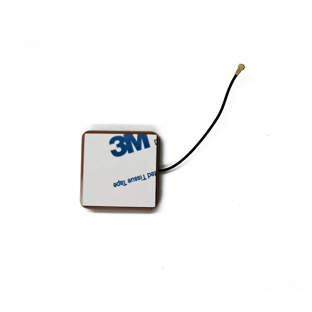
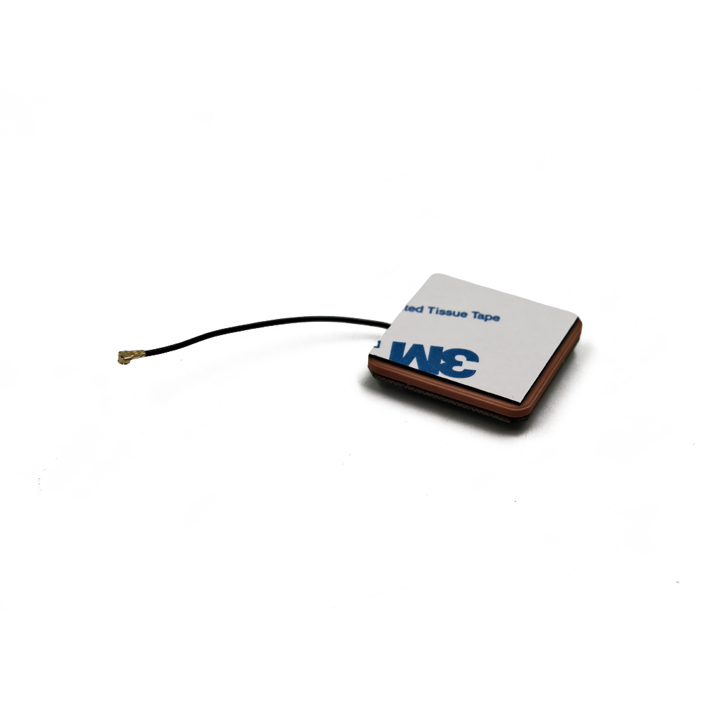
Another key advantage is their compact size. Thanks to the high dielectric constant of ceramic materials, the antenna element can be manufactured in a much smaller form factor compared to traditional antennas without sacrificing performance. This miniaturization makes active GNSS ceramic antennas highly suitable for integration into small - form - factor devices, such as smartphones, wearables, and miniature drones. The small size also offers greater flexibility in device design, allowing for optimal placement of the antenna to maximize signal reception.
Durability is a notable strength of active GNSS ceramic antennas. Ceramic materials are highly resistant to environmental factors such as temperature variations, moisture, and mechanical stress. They can withstand extreme temperatures, ranging from sub - zero cold to high heat, without significant degradation in performance. Additionally, the ceramic antenna element is less prone to damage from impacts or vibrations, making the antenna reliable for use in a wide range of applications, including those in harsh environments such as industrial settings, outdoor adventures, and maritime operations.
The active nature of these antennas also provides advantages in terms of signal processing. The built - in amplifier circuit can be optimized to deliver a consistent and stable gain across a wide range of operating conditions. This helps to ensure that the GNSS receiver receives signals of a consistent quality, reducing the likelihood of errors in positioning calculations. Moreover, the inclusion of filters in the active circuit improves the signal - to - noise ratio, further enhancing the accuracy and reliability of the positioning system.
Challenges
Despite their numerous advantages, active GNSS ceramic antennas face several challenges. One of the primary challenges is electromagnetic interference (EMI). In modern electronic devices, there are numerous components that generate electromagnetic fields, which can interfere with the operation of the GNSS antenna. Components such as wireless communication modules, power supplies, and digital circuits can all be sources of EMI. To mitigate EMI, careful design and layout of the PCB in the antenna module and the host device are required. Shielding techniques, such as using metal enclosures or conductive coatings, may also be employed, but these measures can increase the complexity and cost of the design.
Power consumption is another significant challenge. The active amplifier circuit in the antenna requires a power supply to operate. While efforts are made to design low - power amplifier circuits, the power consumption can still be a concern, especially in battery - powered devices. High power consumption can reduce the battery life of the device, which is a major drawback for portable applications. Manufacturers are constantly researching and developing new amplifier technologies and circuit designs to reduce power consumption without compromising on performance.
Cost is also a factor that can limit the widespread adoption of active GNSS ceramic antennas. The use of high - quality ceramic materials, advanced semiconductor components for the amplifier circuit, and the need for precise manufacturing and testing processes contribute to the relatively high cost of these antennas. For price - sensitive markets, such as certain segments of the consumer electronics industry, finding ways to reduce the cost while maintaining performance is an ongoing challenge for manufacturers.
High sensitivity active GNSS ceramic antennas are already transforming a wide range of industries by enabling reliable positioning in environments where standard antennas fail. As technology advances and new use cases emerge, their applications will expand further, and innovative trends will shape their design and functionality. This section explores the current key applications of these antennas and the future trends that will drive their evolution.
5.1 Current Key Applications
5.1.1 IoT Asset Tracking
The IoT asset tracking market is one of the largest adopters of high sensitivity active GNSS ceramic antennas, as it requires reliable positioning of assets in diverse environments—from shipping containers in ports to delivery packages in urban areas.
Shipping and Logistics: Shipping containers stacked in ports are surrounded by metal structures that block GNSS signals, resulting in weak or intermittent signal reception. High sensitivity antennas can capture these weak signals, enabling real-time tracking of containers as they move through ports, onto ships, and to their final destinations. For example, a logistics company using high sensitivity antennas in its container trackers can reduce the time spent searching for misplaced containers by 40%, improving operational efficiency and reducing costs.
Last-Mile Delivery: Delivery drones and vehicles operating in urban canyons face challenges with weak GNSS signals due to tall buildings. High sensitivity antennas allow these devices to maintain positioning accuracy of 5-10 meters, ensuring that packages are delivered to the correct address. For example, a drone delivery service in a major city can use high sensitivity antennas to navigate between skyscrapers and deliver packages to rooftop drop-off points with minimal errors.
Cold Chain Logistics: Assets in cold chain logistics (e.g., refrigerated trucks transporting food or pharmaceuticals) require positioning and temperature monitoring. High sensitivity antennas are designed to operate in extreme temperatures (-40°C to 85°C), making them suitable for this application. The antenna’s low power consumption also ensures that the tracker’s battery lasts for months, even in cold conditions where battery performance typically degrades.
5.1.2 Automotive and Autonomous Vehicles
The automotive industry relies on high sensitivity active GNSS ceramic antennas for telematics, navigation, and autonomous driving—applications that require precise and reliable positioning in all environments.
Telematics: Automotive telematics devices use GNSS antennas to track vehicle location, speed, and driver behavior. High sensitivity antennas ensure that these devices can maintain positioning even when the vehicle is in urban canyons or under bridges—critical for fleet management and insurance telematics (e.g., pay-as-you-drive insurance). For example, a fleet management company can use high sensitivity antennas to monitor the location of its trucks in real time, optimizing routes and reducing fuel consumption by 15%.
Advanced Driver Assistance Systems (ADAS): ADAS features like adaptive cruise control and lane-keeping assist require precise positioning to function correctly. High sensitivity antennas provide the sub-10-meter accuracy needed for these systems, even in weak-signal environments. For example, an ADAS-equipped car using a high sensitivity antenna can maintain its lane position on a highway surrounded by tall trees, which would block signals for standard antennas.
Autonomous Vehicles: Fully autonomous vehicles require centimeter-level positioning accuracy to navigate safely. While high sensitivity active GNSS ceramic antennas alone cannot achieve this level of accuracy, they are a critical component of hybrid positioning systems that combine GNSS with other technologies—such as LiDAR, radar, and inertial measurement units (IMUs). The antenna provides the base GNSS positioning, while the other technologies correct for errors and fill in gaps when GNSS signals are weak.
5.1.3 Wearable Devices
Wearable devices like smartwatches, fitness trackers, and medical wearables use high sensitivity active GNSS ceramic antennas to provide location-based features—while maintaining a compact form factor and long battery life.
Fitness and Outdoor Wearables: Fitness trackers and outdoor smartwatches use GNSS antennas to track running routes, hiking trails, and cycling distances. High sensitivity antennas allow these devices to maintain positioning accuracy in dense forests or mountainous areas, where signals are scattered by trees and terrain. For example, a hiker using a smartwatch with a high sensitivity antenna can track their location in a dense pine forest, where a standard antenna would lose signal.
Medical Wearables: Medical wearables for patients with chronic conditions (e.g., Alzheimer’s disease or diabetes) use GNSS antennas to provide real-time location monitoring. High sensitivity antennas ensure that these devices can track patients even when they are indoors (e.g., in a hospital or nursing home) or in urban areas. For example, a caregiver can use a medical wearable with a high sensitivity antenna to track a patient with Alzheimer’s who wanders into a shopping mall, ensuring their safe return.
Sports Performance Monitoring: Professional sports teams use wearables with GNSS antennas to monitor athletes’ movements and performance during training and games. High sensitivity antennas provide accurate positioning data even in stadiums surrounded by large structures (e.g., bleachers or scoreboards), allowing coaches to analyze players’ speed, distance covered, and positioning on the field.
5.1.4 Smart Cities and Urban Infrastructure
Smart cities use high sensitivity active GNSS ceramic antennas to monitor and manage urban infrastructure—such as traffic lights, streetlights, and waste management systems.
Traffic Management: Smart traffic lights and traffic cameras use GNSS antennas to synchronize their operations and monitor traffic flow. High sensitivity antennas allow these devices to maintain time synchronization (critical for traffic light coordination) even in urban canyons, where standard antennas struggle with weak signals. For example, a city can use high sensitivity antennas in its traffic management system to reduce traffic congestion by 25% by optimizing traffic light timing based on real-time traffic flow.
Waste Management: Smart waste bins equipped with GNSS trackers use high sensitivity antennas to alert waste management teams when they are full. These trackers operate in urban areas and near buildings, where signals are weak, but the high sensitivity antenna ensures that the bin’s location is always visible. For example, a city can reduce fuel consumption by 30% by using these trackers to optimize waste collection routes, avoiding unnecessary trips to empty bins.
Infrastructure Monitoring: Sensors attached to bridges, tunnels, and buildings use high sensitivity GNSS antennas to monitor structural health and detect movement (e.g., due to earthquakes or erosion). The antenna’s ability to operate in remote or urban areas ensures that these sensors can provide continuous data, helping engineers identify potential structural issues before they become critical.
5.2 Future Trends
5.2.1 Integration with AI for Adaptive Signal Optimization
One of the most promising future trends for high sensitivity active GNSS ceramic antennas is the integration of artificial intelligence (AI) to enable adaptive signal optimization. AI algorithms will analyze real-time data from the antenna (e.g., signal strength, noise levels, and interference sources) and adjust the antenna’s parameters (e.g., gain, resonant frequency, and filter bandwidth) to maximize performance in changing environments.
Real-Time Interference Mitigation: AI algorithms will detect interference from sources like Wi-Fi or cellular networks and adjust the filter’s bandwidth to attenuate the interfering signal. For example, if the antenna detects a strong 2.4 GHz Wi-Fi signal, the AI can narrow the filter’s passband to block the Wi-Fi frequency while maintaining coverage of GNSS bands.
Dynamic Gain Adjustment: The AI will adjust the LNA’s gain based on signal strength—increasing gain for ultra-weak signals (-170 dBm) and reducing gain for stronger signals (-150 dBm) to avoid distortion. This dynamic adjustment will improve the antenna’s linearity and reduce power consumption, as the LNA does not need to operate at maximum gain at all times.
Predictive Maintenance: AI will analyze historical performance data to predict when the antenna may fail (e.g., due to component degradation or environmental damage). This allows for proactive maintenance, reducing downtime for critical applications like autonomous vehicles or asset tracking.
AI integration will require the antenna to include a small microcontroller and memory to run the algorithms, but advances in low-power microchips will ensure that this does not significantly increase the antenna’s power consumption or size.
5.2.2 Miniaturization with MEMS Technology
Micro-Electro-Mechanical Systems (MEMS) technology will drive further miniaturization of high sensitivity active GNSS ceramic antennas, making them suitable for even smaller devices—such as tiny IoT sensors, implantable medical devices, and smart contact lenses.
MEMS-Based Ceramic Elements: MEMS technology allows for the fabrication of ceramic elements with dimensions as small as 2mm × 2mm × 0.5mm—far smaller than current 6mm × 6mm antennas. These tiny elements use microfabrication techniques to create precise patch structures and ground planes, ensuring that they maintain high sensitivity despite their size.
Integrated MEMS LNAs: MEMS technology can also be used to fabricate ultra-small LNAs using GaAs or SiGe transistors. These MEMS LNAs have a noise figure of 0.5-0.8 dB (same as current LNAs) but occupy only 10% of the space, allowing for full integration of the antenna, LNA, filter, and matching network into a single MEMS chip.
Implantable Medical Applications: Miniaturized high sensitivity antennas using MEMS technology will enable new implantable medical devices—such as glucose sensors or pacemakers with location tracking. These devices can use the antenna to transmit location data to external receivers, allowing doctors to monitor patients’ movements and ensure that the device remains in place.
MEMS-based miniaturization will not only reduce the antenna’s size but also lower its cost, as MEMS devices can be mass-produced using standard semiconductor manufacturing processes.
5.2.3 Multi-Band and Multi-Technology Integration
Future high sensitivity active GNSS ceramic antennas will support an even wider range of frequencies and integrate with other positioning technologies to provide seamless indoor-outdoor positioning.
Expanded GNSS Band Support: In addition to current bands (GPS L1, GLONASS G3, Galileo E1, BeiDou B1), future antennas will support newer GNSS bands—such as GPS L5 (1176.45 MHz), Galileo E5 (1191.795 MHz), and BeiDou B2 (1207.14 MHz). These bands offer better signal penetration and resistance to interference, further improving the antenna’s performance in weak-signal environments.
Integration with UWB and BLE: High sensitivity GNSS antennas will be integrated with UWB and BLE modules in a single package, creating hybrid positioning systems that provide accurate positioning both indoors and outdoors. The GNSS antenna handles outdoor positioning, while UWB or BLE handles indoor positioning—with seamless handoff between the two technologies as the device moves from outdoor to indoor spaces.
5G Integration: 5G networks will provide additional positioning capabilities through cell-based positioning (e.g., timing advance or angle of arrival). Future high sensitivity GNSS antennas will integrate with 5G modules to combine GNSS and 5G positioning, providing even higher accuracy and reliability in urban areas where 5G infrastructure is dense.
5.2.4 Sustainable and Eco-Friendly Designs
As the world focuses on sustainability, future high sensitivity active GNSS ceramic antennas will adopt eco-friendly designs to reduce their environmental impact.
Recyclable Materials: Manufacturers will use recyclable ceramic materials (e.g., alumina, which is fully recyclable) and biodegradable encapsulation materials (e.g., plant-based epoxies) to reduce waste. These materials will maintain the antenna’s performance while making it easier to recycle at the end of its lifespan.
Energy Harvesting: Antennas will integrate small energy harvesting modules—such as solar cells or vibration harvesters—to power the LNA and other components. This will reduce reliance on disposable batteries, making the antenna more sustainable for long-term IoT applications (e.g., sensors deployed in remote areas).
Low-Power Manufacturing: Manufacturing processes for high sensitivity antennas will be optimized to reduce energy consumption. For example, sputtering processes used to deposit conductive layers on ceramic elements will use less energy, and curing processes for encapsulation materials will operate at lower temperatures.
Conclusion
High sensitivity active GNSS ceramic antennas represent a transformative technology in the field of positioning, addressing the critical limitation of standard antennas—their inability to operate reliably in weak-signal environments. By combining a compact ceramic element, ultra-low-noise LNA, and high-performance filter, these antennas can detect signals as low as -165 dBm to -170 dBm, enabling reliable positioning in urban canyons, indoor spaces, dense forests, and remote rural areas. Their small size (6mm × 6mm to 15mm × 15mm), low power consumption (5-10 mA), and multi-constellation support make them indispensable for a wide range of applications—from IoT asset tracking to autonomous vehicles and wearable devices.
As we have explored, these antennas offer significant advantages over standard GNSS antennas: they expand the range of environments where positioning is possible, integrate seamlessly into space-constrained devices, and reduce operational costs for industries like logistics and automotive. However, they also face challenges—including higher cost, sensitivity to EMI, temperature-induced performance degradation, and limited indoor positioning capabilities. These challenges are being addressed through innovations like low-cost SiGe LNAs, temperature-compensating materials, and hybrid positioning systems, making high sensitivity active GNSS ceramic antennas more accessible and versatile.
Looking to the future, the evolution of these antennas will be driven by AI integration, MEMS-based miniaturization, multi-technology fusion, and sustainable design. AI will enable adaptive signal optimization, ensuring that the antenna performs optimally in changing environments. MEMS technology will shrink the antenna to microscopic sizes, opening up new applications in implantable medical devices and tiny IoT sensors. Integration with 5G, UWB, and BLE will provide seamless indoor-outdoor positioning, eliminating the gap between outdoor GNSS and indoor positioning. And sustainable designs will reduce the antenna’s environmental impact, aligning with global efforts to build a more eco-friendly electronics industry.
In conclusion, high sensitivity active GNSS ceramic antennas are not just a technical advancement—they are a enabler of a more connected, efficient, and safe world. By making reliable positioning ubiquitous, they will transform industries, improve the user experience of consumer devices, and support the development of smart cities and autonomous systems. As technology continues to advance, these antennas will remain at the forefront of positioning innovation, helping to shape the future of how we track, navigate, and interact with the world around us.

 86 0755 2819 9597
Lucy Yang | lucy.y@toxutech.com
Nicole Li | nicole@toxutech.com
Dotty Zhao | sales04@toxutech.com
Global Business Director / Sales Team / Global Operations


 En
En Cn
Cn Korean
 Home >


