Combo Antenna Combo Antenna

Language
Built-in RTK GPS Antenna
GNSS Car Antenna
GNSS Car Antenna

GPS & GNSS Antenna

Home >  GPS & GNSS Antenna > 

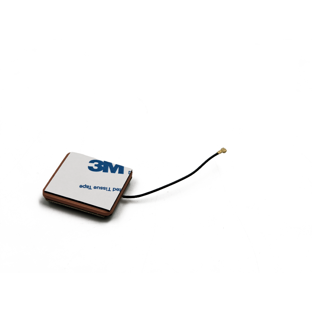
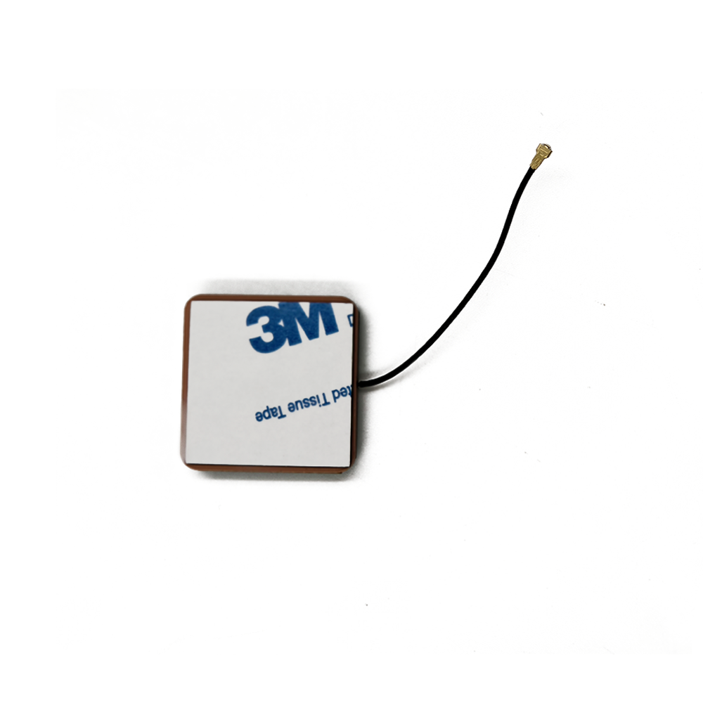
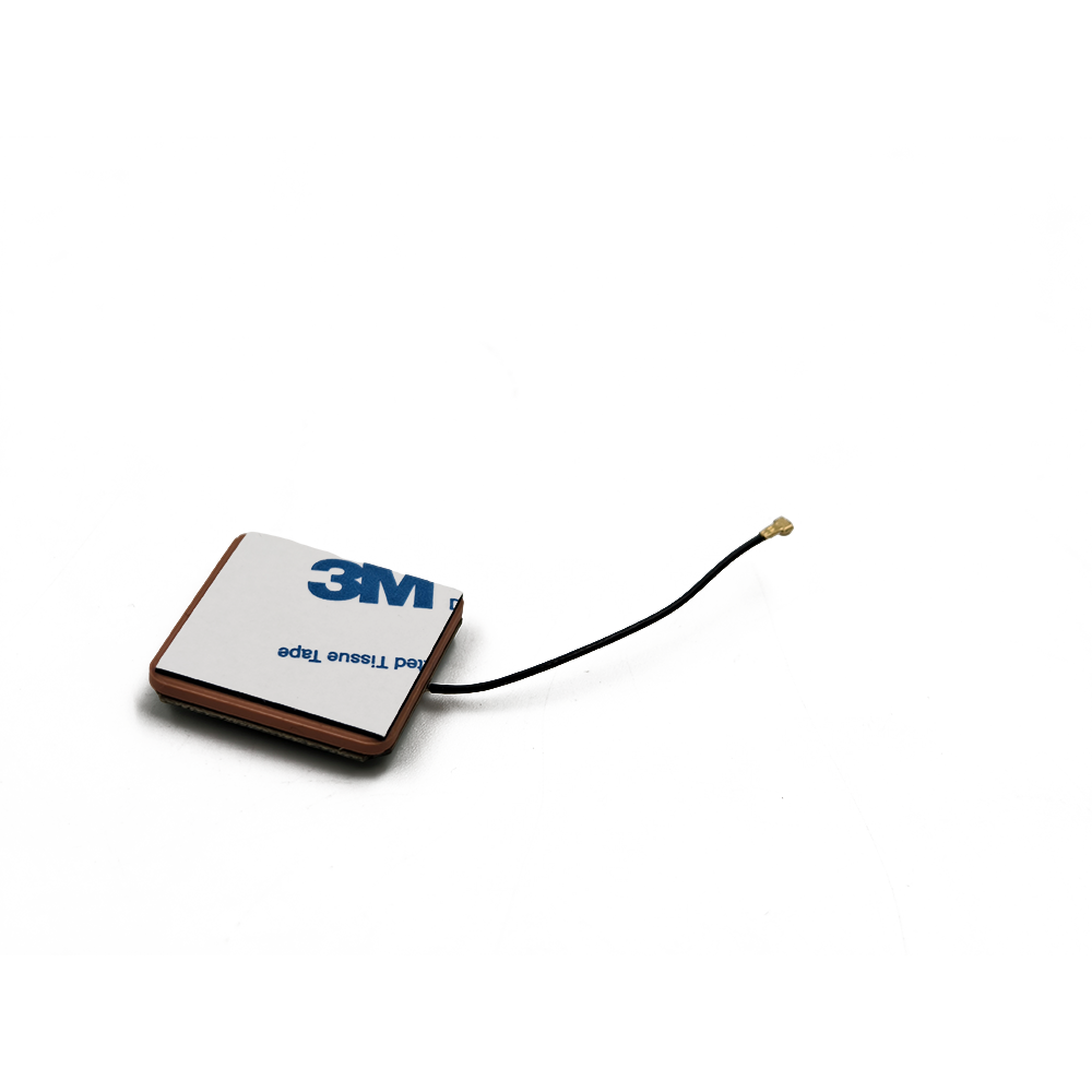
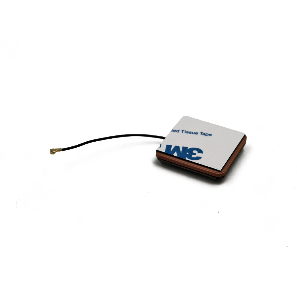
high precision ceramic patch GPS antenna

The Global Positioning System (GPS) and other Global Navigation Satellite Systems (GNSS) like GLONASS, Galileo, and BeiDou have become the invisible backbone of modern technology. From navigating city streets to synchronizing financial transactions and guiding agricultural equipment, the ability to pinpoint one's location with centimeter-level accuracy has revolutionized countless industries. At the heart of any high-precision GNSS receiver lies its most critical and defining component: the antenna. Among the various antenna types, the ceramic patch antenna has emerged as the undisputed champion for high-precision applications, offering a unique blend of performance, reliability, and manufacturability.


Leave a message Contact

Fill in your email address

Or you can continue to download without filling in

Overview

A high-precision ceramic patch GPS antenna is a type of microstrip antenna, a flat, compact radiator that is fabricated using a ceramic substrate. Unlike the simple, consumer-grade antennas found in smartphones or car navigation systems, these antennas are engineered for exceptional performance. Their primary mission is not just to receive signals, but to receive them with utmost fidelity, phase stability, and resilience against environmental interference, enabling differential correction techniques like RTK (Real-Time Kinematic) and PPP (Precise Point Positioning) to achieve their remarkable accuracy.

The journey of the patch antenna began in the 1970s, following the seminal work of researchers like Robert E. Munson and John Q. Howell. The invention of low-loss ceramic materials with high dielectric constants (εr) was the key catalyst for their miniaturization and widespread adoption. A high dielectric constant allows the antenna's physical size to be reduced significantly (as the wavelength within the material is shortened by a factor of √εr) while maintaining its required electrical resonant frequency. This made ceramic patches ideal for integration into small, portable, and aesthetically pleasing devices without sacrificing performance.

The defining characteristic of a high-precision antenna is its focus on phase center stability. The phase center is the hypothetical point from which the antenna's transmitted or received electromagnetic radiation appears to emanate. In high-precision GNSS, we measure the phase of the carrier wave, not just the travel time of the code. Any movement of the antenna's electrical phase center relative to its physical reference point (e.g., the mounting hole) introduces a measurable error. High-precision antennas are meticulously designed to have a phase center that is stable, well-defined, and consistent across all angles of arrival and frequencies. This stability is paramount because any uncalibrated shift translates directly into a positional error.

Furthermore, these antennas are designed to be highly right-hand circularly polarized (RHCP). GPS satellites transmit RHCP signals to mitigate signal degradation caused by reflections and atmospheric effects. A high-quality antenna efficiently rejects the opposite polarization (LHCP - Left-Hand Circular Polarization), which is typically generated by multipath signalssignals that have bounced off the ground, buildings, or other objects before reaching the antenna. Multipath is a primary source of error in GNSS, and a good antenna is the first line of defense against it.

In summary, the high-precision ceramic patch antenna is far more than a simple piece of metal and ceramic. It is a sophisticated electromagnetic device engineered to be the stable and sensitive gateway for weak satellite signals. It forms the critical front-end of a chain of technology that transforms radio waves traveling from space into a precise position on Earth, enabling the incredible accuracy that defines modern high-stakes navigation and timing applications. Its overview sets the stage for understanding the intricate design, physics, and application-specific considerations that follow.


Design and Construction

The design of a high-precision ceramic patch antenna is a complex multidisciplinary endeavor, balancing electromagnetic theory, materials science, and precision engineering. Every layer, material, and dimension is meticulously chosen and optimized to achieve the stringent requirements of phase center stability, bandwidth, gain, and multipath rejection.

Core Components and Materials:

Ceramic Substrate (Patch Radiator): This is the heart of the antenna. The choice of ceramic is the most critical decision. High-purity materials like aluminum oxide (Al2O3) or titanium-based ceramics are common. They are selected for their:

High Dielectric Constant (εr): Typically between 20 and 40. This enables a drastic reduction in the physical size of the antenna. The resonant length of the patch is approximately λ/(2√εr), where λ is the free-space wavelength.

Low Loss Tangent (tan δ): This measures the rate of energy absorption and conversion to heat. A very low loss tangent (e.g., < 0.002) is essential for high efficiency, ensuring that minimal signal power is lost within the substrate itself, maximizing the signal-to-noise ratio (SNR) delivered to the receiver.

Temperature Stability: The dielectric constant must remain stable over a wide operating temperature range (-40°C to +85°C is standard). Temperature fluctuations can shift the resonant frequency and, more critically, destabilize the phase center. Advanced ceramics are engineered with specific dopants to minimize this thermal drift.

Patch Element: This is a thin layer of conductive material (usually silver or gold) printed, fired, or plated onto the top surface of the ceramic substrate. Its shape is most often square or rectangular, but can be circular or have specific notches. Its dimensions (length L and width W) primarily determine the fundamental resonant frequency. The design is a trade-off: a larger patch offers higher gain and bandwidth but defeats the purpose of miniaturization.

Ground Plane: A continuous layer of conductor on the bottom surface of the ceramic substrate. It serves two key functions: it defines the antenna's radiation pattern, creating a directional "front hemisphere" of sensitivity, and it acts as an electromagnetic shield, blocking noise and interference from the electronics below the antenna. Its size significantly influences the antenna's gain pattern and its ability to reject multipath from low elevation angles.

Feeding Mechanism: This is how electromagnetic energy is coupled between the antenna and the coaxial cable. The method is crucial for impedance matching (typically to 50 Ohms).

Probe Feed: A conductive pin is soldered to the patch and passes through a hole drilled in the substrate and ground plane to connect to the center conductor of the coaxial cable. It is robust but can introduce unwanted inductance.

Aperture-Coupled Feed: The patch is electromagnetically coupled to a microstrip feed line located on a separate, underlying substrate layer through a slot in the ground plane. This allows independent optimization of the radiating and feeding structures, offering excellent bandwidth and isolation, but is more complex to manufacture.

Coaxial Feed (Edge-fed): The center conductor of the coaxial cable is connected directly to the edge of the patch. This is simple but can be mechanically unreliable and is sensitive to cable movement.

Bandwidth Enhancement Techniques: A bare patch antenna has a very narrow bandwidth (~1-2%). For modern GNSS, which requires reception of multiple frequencies (e.g., L1, L2, L5, L-band), this is wholly inadequate. Engineers employ several techniques to broaden the bandwidth:

Stacked Patches: A second, slightly larger parasitic patch is placed above the primary fed patch, separated by a low-dielectric spacer. This creates a second resonant frequency. By carefully tuning both patches and their coupling, a wide, dual-band, or even triple-band response can be achieved.

Slot Cutting: Introducing U-shaped or other slots on the patch surface can perturb the current paths, creating multiple closely-spaced resonances that merge to form a wider operating bandwidth.

Modified Shapes: Using a truncated corner or a nearly-square shape can also excite multiple modes to enhance bandwidth.

Housing and Radome: The fragile ceramic element is housed in a protective enclosure. The base is often made of metal (acting as an extended ground plane) or high-quality plastic. The top cover, or radome, must be made of a material that is virtually transparent to RF signals (e.g., ABS, PPS, or ceramic itself). Its shape and material properties are designed to minimize signal reflection and attenuation. The entire housing is typically sealed to IP67 or higher standards to protect against moisture and dust.

The assembly process requires extreme precision. Misalignment of the patch, feeding point, or ground plane by even a fraction of a millimeter can detune the antenna, distort its radiation pattern, and, most damagingly, shift its phase center. The final step is rigorous testing in an anechoic chamber to measure its gain pattern, axial ratio (a measure of circular polarization purity), return loss (S11), and, most importantly, its phase center variation (PCV). A PCV map is created and used to calibrate the antenna, with these corrections often applied in the post-processing software or firmware of the high-precision receiver. This entire intricate construction process transforms raw materials into a highly calibrated scientific instrument.


Working Principles

The operation of a ceramic patch antenna is elegantly explained by fundamental electromagnetic principles. Its function is to convert the electromagnetic energy of a passing radio wave into an oscillating electrical current in a circuit (reception), and vice versa (transmission). For high-precision GPS, we are solely concerned with its role as a receiver.

Fundamental Resonance:

A patch antenna is essentially a resonant cavity. The ceramic substrate acts as a dielectric cavity bounded on the top and bottom by conductors (the patch and the ground plane). The sides are considered magnetic walls. The antenna is designed to operate in its fundamental TM₁₀ mode. In this mode, the resonant length L of the patch is approximately half the wavelength in the dielectric material (λ_d / 2). Since the wavelength in the dielectric is λ₀ / √εr (where λ₀ is the free-space wavelength), the physical length L is given by:

L ≈ λ₀ / (2 * √εr)

For a GPS L1 frequency (1575.42 MHz, λ₀ ≈ 19 cm) and a ceramic with εr = 36, the patch length L becomes about 19 / (2 * 6) = 1.58 cm, demonstrating the dramatic size reduction.

When the antenna is at resonance, the electromagnetic fields underneath the patch form a standing wave. The electric field is maximum at the edges of the patch and zero at the center, while the current is maximum at the center and zero at the edges. This specific field distribution is what determines the radiation pattern and polarization.

Radiation Mechanism:

The radiation occurs primarily from the fringing fields at the edges of the patch. The electric field lines fringe out from the radiating edges (the edges of length L), creating an equivalent set of radiating slots. These two slots, separated by the length L, are the primary sources of radiation. Their radiation patterns combine to create a broad, directional beam perpendicular to the plane of the antenna.

Circular Polarization Generation:

GPS signals use Right-Hand Circular Polarization (RHCP) to combat Faraday rotation in the ionosphere and to discriminate against reflected (multipath) signals, which often reverse their polarization (becoming LHCP). A simple square patch excited at a single point produces linear polarization. To create circular polarization, two orthogonal modes with equal amplitude and a 90-degree phase difference must be excited. This is achieved by:

Single Feed with Perturbation: The most common method for ceramic patches. A small physical perturbation, like a notch cut diagonally opposite corners or a tab added to the edge, unbalances the two modes and creates the necessary phase shift.

Dual Feed: Two separate feed points are used, located on adjacent edges of the patch. A external 90-degree hybrid coupler (like a branch-line coupler) is then used to feed these points with the required phase difference. This method offers superior polarization purity (low axial ratio) across a wider angular range but is more complex and larger.

Phase Center and its Criticality:

This is the most crucial concept for high-precision work. The antenna does not receive a signal at a single mathematical point; the perceived point of reception (the phase center) shifts slightly depending on the direction (elevation and azimuth) from which the signal arrives. This is known as Phase Center Variation (PCV). In high-precision GNSS, where carrier-phase measurements are used, an unaccounted-for 1mm shift in the phase center translates directly into a 1mm error in the calculated position.

The design goal is to minimize these variations and make them highly predictable. A well-designed antenna will have a stable phase center that is consistent across different frequencies. Antenna manufacturers use sophisticated anechoic chamber measurements to create a detailed PCV map for each antenna model. This map, often provided as a calibration file in ANTEX (ANTenna EXchange) format, is used by processing software to correct the raw phase measurements, effectively moving the calculated position back to a known, stable reference point (the Antenna Reference Point or ARP). This calibration is what separates a high-precision antenna from a consumer-grade one.

Multipath Rejection:

The antenna's structure is its first defense against multipath. Multipath signals arrive from low elevation angles or after reflecting off surfaces. The antenna combats this through:

The Ground Plane: A large ground plane prevents the antenna from "seeing" signals coming from below the horizon, attenuating low-angle multipath.

RHCP Selectivity: Since multipath signals often become LHCP upon reflection, the antenna's inherent design to receive RHCP signals naturally rejects a portion of this interfering energy.

Gain Pattern (Choke Rings): For the most demanding applications, the antenna is mounted on a "choke ring" ground plane. This corrugated metal structure presents a high impedance surface to signals arriving at grazing angles, creating a deep null in the antenna's pattern at the horizon and further suppressing multipath.

In essence, the working principle is a careful orchestration of resonance, field manipulation, and precise mechanical design to act as a highly selective, stable, and sensitive transducer for faint signals from space.


Advantages and Challenges

The dominance of ceramic patch antennas in high-precision GNSS is due to a compelling set of advantages. However, achieving this performance is not without significant engineering challenges and inherent trade-offs.

Advantages:

Compact Size and Low Profile: The high dielectric constant of ceramics is their greatest asset. It allows for a very small form factor, making these antennas ideal for integration into portable devices, drones, automotive modules, and consumer electronics where space is at a premium. Their flat, low-profile "patch" design is also aesthetically pleasing and aerodynamically neutral.

Robustness and Durability: The ceramic substrate is a rigid, hard, and environmentally stable material. It is resistant to corrosion, humidity, UV radiation, and can withstand significant mechanical vibration and shock. Once housed in a sealed radome, the entire assembly becomes a highly reliable component suitable for harsh outdoor and automotive environments.

Ease of Manufacture and Integration: Despite the design complexity, the basic structure is planar and compatible with standard printed circuit board (PCB) and ceramic fabrication techniques like printing, firing, and plating. This allows for mass production and consistent quality control. Their simple physical interface (often a single coaxial connector and mounting holes) simplifies integration into larger systems.

Conformal Design and Array Integration: The flat nature of patch antennas allows them to be easily mounted on flat surfaces. Furthermore, multiple patch elements can be arranged in a planar array on a single substrate to create a more complex antenna system. This is the basis for advanced Controlled Reception Pattern Antennas (CRPAs) used in military and automotive applications for jamming resistance and beam-steering.

Cost-Effectiveness at Scale: While the R&D and calibration costs are high, the unit cost for a standard ceramic patch antenna can be relatively low when manufactured in large volumes. This has been key to their proliferation beyond specialized surveying into mass markets like automotive and IoT.

Challenges and Limitations:

Inherently Narrow Bandwidth: This is the primary fundamental limitation of a simple patch antenna. The high Q-factor of the resonant cavity, exacerbated by the high dielectric constant, results in a very narrow operating bandwidth. As GNSS expands to include more frequencies (L1, L2, L5, L-band for corrections), overcoming this requires complex techniques like stacked patches or slot loading, which increase cost, thickness, and design complexity.

Efficiency Trade-offs: While the ceramic allows for miniaturization, it also concentrates the electromagnetic fields within itself. This increases conductor and dielectric losses, especially if the material has a less-than-ideal loss tangent. Furthermore, a smaller antenna has a smaller effective aperture, which can limit its gain. The quest for a smaller size often directly conflicts with the goals of high efficiency and bandwidth.

Thermal Sensitivity: Although advanced ceramics are thermally stable, they are not perfectly so. The dielectric constant still changes slightly with temperature, which shifts the resonant frequency and, more problematically, can cause the phase center to drift. For the most demanding geodetic applications, this thermal drift must be meticulously characterized and modeled, adding another layer of complexity.

Manufacturing Tolerances and Consistency: The performance is exquisitely sensitive to dimensional tolerances. A slight variation in the ceramic's dielectric constant, thickness, or the alignment of the feed point during mass production can shift the frequency, worsen the axial ratio (polarization purity), and, most critically, alter the phase center characteristics. Maintaining tight process control is essential and expensive.

Multipath Performance vs. Size: A larger ground plane is better for multipath rejection. However, a small, integrated antenna has a limited ground plane, often relying on the host device's PCB. This can lead to compromised performance as the antenna's pattern becomes distorted by the nearby electronics and the irregular ground plane of the device itself. This is a major challenge for smartphone and wearable integration.

In conclusion, the ceramic patch antenna represents a series of elegant engineering compromises. Its advantages of small size, robustness, and manufacturability make it the perfect choice for modern applications. However, extracting high-precision performance from it requires a deep understanding of electromagnetic theory and sophisticated design techniques to overcome its inherent limitations of bandwidth, efficiency, and sensitivity to the environment and manufacturing variances.


Applications and Future Trends

The unique capabilities of high-precision ceramic patch antennas have enabled a technological revolution across a diverse spectrum of industries. Their journey began in specialized fields but is rapidly expanding into mass-market applications.

Current Applications:

Geomatics and Surveying: This is the traditional and most demanding domain. RTK-GPS systems used for land surveying, construction site preparation, and civil engineering require the ultimate in phase center stability and multipath rejection. These antennas are often mounted on fixed-height poles or integrated into ruggedized, survey-grade receivers, sometimes coupled with external choke rings for the most challenging environments.

Precision Agriculture (AgriTech): This is a major growth area. GPS-guided tractors and harvesters use RTK for auto-steering, achieving sub-inch pass-to-pass accuracy. This eliminates overlaps and gaps in planting, spraying, and harvesting, leading to massive savings in fuel, seed, fertilizer, and time. Variable Rate Technology (VRT) uses precise position data to apply inputs only where needed.

Unmanned Aerial Vehicles (Drones) and Robotics: The small size and light weight of ceramic patches make them ideal for drones. They are used for precision mapping, photogrammetry, agricultural spraying, and infrastructure inspection. In robotics, they enable autonomous navigation for warehouse robots, lawn mowers, and last-mile delivery vehicles.

Marine and Autonomous Shipping: High-precision GNSS is critical for harbor navigation, dredging, hydrographic surveying, and the emerging field of autonomous surface vessels. The antenna's ruggedness and corrosion resistance are key benefits in the harsh marine environment.

Aviation: Aircraft navigation, especially during approach and landing phases (GBAS - Ground-Based Augmentation System), requires extremely high integrity and precision. Ceramic patch arrays are used in aviation-grade receivers.

Scientific and Timing Applications: Scientific applications like crustal deformation monitoring for earthquake prediction and glacier flow tracking require long-term, millimeter-level stability. GNSS is also a primary source for precise time synchronization in telecommunications networks (4G/5G base stations), financial trading networks, and power grids, where a stable antenna phase center is critical for nanosecond-level timing accuracy.

Automotive and Autonomous Vehicles (ADAS): This is the frontier for mass adoption. Lane-level positioning is crucial for Advanced Driver Assistance Systems (ADAS) and the path towards full autonomy. High-precision ceramic patches are being integrated into vehicle rooflines and dashboards to provide continuous, reliable position, velocity, and time (PVT) data, fusing with LiDAR, radar, and cameras.

Future Trends:

Multi-Band, Multi-Constellation Operation: The future is about receiving all signals from all constellations (GPS, Galileo, GLONASS, BeiDou) across all frequencies (L1, L2, L5, etc.). This "constellation redundancy" improves accuracy, availability, and reliability. Antenna design will focus on achieving ultra-wideband performance covering 1.1 GHz to 1.6 GHz in a single, compact element.

Integrated Active Antennas: The trend is towards tighter integration of the antenna element with a Low-Noise Amplifier (LNA) and often a bandpass filter into a single sealed module. This "active antenna" improves the overall system noise figure and protects the weak signal from being degraded by loss in the coaxial cable before amplification.

Advanced Multipath Mitigation: Research continues into improving built-in multipath rejection without increasing size. This includes designs with integrated artificial magnetic conductor (AMC) surfaces or electromagnetic bandgap (EBG) structures that act like miniature, integrated choke rings.

Antenna Arrays and Beamforming: For automotive and other challenging environments, single antennas are vulnerable to jamming and spoofing. The future lies in multi-element ceramic patch arrays that can electronically steer their beam towards desired satellites and null interference sources. This Controlled Reception Pattern Antenna (CRPA) technology is becoming more compact and affordable.

"Smart" or Cognitive Antennas: Integrating processing capabilities with the antenna to allow it to adapt in real-time to its RF environmentfor example, by dynamically adjusting its pattern to nullify a newly detected jamming signal.

Enhanced Integration and Aesthetics: For consumer automotive, the antenna must disappear. Future designs will be fully integrated into the vehicle's glass (as printed patches), body panels, or plastic components, providing high performance without a visible "shark-fin" or puck.

The high-precision ceramic patch antenna, therefore, is not a static technology. It is continuously evolving to meet the ever-increasing demands of accuracy, reliability, and integration, solidifying its role as the essential gatekeeper to the world of precise positioning.

Conclusion

The high-precision ceramic patch GPS antenna is a masterpiece of engineering that exemplifies the profound impact a single, well-designed component can have on an entire technological ecosystem. It is far more than a passive receiver; it is the critical front-end that defines the ultimate performance ceiling of any high-precision GNSS system. Its journey from a theoretical concept to a mass-produced, highly calibrated instrument underscores its successful balance of physics, materials science, and practical application needs.

This series has detailed its inner workings: from its overview as the foundation of modern positioning, through the meticulous design and construction that transforms ceramic and metal into a resonant cavity, to the fundamental physics that govern its operation. We have seen that its core value lies in its exceptional phase center stability, a characteristic that allows carrier-phase measurements to be translated into centimeter-level position accuracy. Its ability to reject multipath through careful pattern shaping and polarization purity further cements its role as the first and most important line of defense against error.

While it boasts significant advantages in size, robustness, and manufacturability, these benefits are not without their challenges. Engineers perpetually wrestle with the trade-offs between bandwidth, efficiency, size, and thermal stability. Overcoming these limitations requires continuous innovation in materials, feeding techniques, and bandwidth-enhancement strategies like stacked patches.

The applications for this technology are vast and growing, enabling revolutions in surveying, agriculture, robotics, and setting the stage for the autonomous future of transportation. As we look forward, the trends are clear: the antenna will become more integrated, more wideband, more intelligent, and even more central to systems that rely on flawless absolute positioning.

In conclusion, as GNSS signals travel over 20,000 km from medium Earth orbit, they arrive at Earth's surface incredibly weak and corrupted by a myriad of errors. The high-precision ceramic patch antenna stands as the dedicated sentinel, designed to capture these faint whispers from space with unwavering fidelity and stability. It is the indispensable gateway, the precise and stable starting point upon which all subsequent signal processing and calculation is built, making it the true cornerstone of modern high-precision navigation.


high precision ceramic patch GPS antenna

Have questions?

Shenzhen Tongxun Precision Technology Co., Ltd. Technical Consultants are here to assist you!

high precision ceramic patch GPS antenna18665803017 (Macro)

high precision ceramic patch GPS antennasales@toxutech.com

Leave a message

Leave a Message

Your Name *

Email *

Tel

Content *

GPS Active GPS Antenna GNSS RTK Antenna
GNSS RTK Antenna