

-
Products -PCBA Manufacturing RF Connectors RF Cable Assemblys Embedded Antennas External Antennas Positioning Chips and Modules
RF Connectors

RF Cable Assemblys
Embedded Antennas
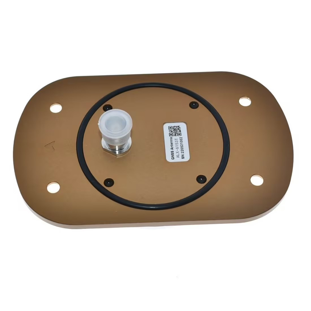
External Antennas
Positioning Chips and Modules


 Language


Language


In the realm of aviation, navigation is not merely a matter of convenience; it is the bedrock of safety, efficiency, and operational capability. The evolution from ground-based navigation aids like VOR and ILS to satellite-based systems represents the most significant shift in aviation history since the invention of the radio. At the forefront of this revolution is the High-Precision Real-Time Kinematic (RTK) Aviation GNSS Antenna, a specialized device engineered to meet the extreme demands of the aerial environment.
An Aviation RTK GNSS antenna is not a consumer-grade component. It is a highly specialized sensor designed to provide continuous, reliable, and supremely accurate positioning data for aircraft, enabling applications that range from precision approach and landing to autonomous flight and aerial surveying. Its core function is to act as the primary interface between the global constellation of navigation satellites and the aircraft's avionics suite, capturing incredibly weak signals and preparing them for processing with absolute fidelity.
The "High-Precision" and "RTK" qualifications are what separate it from a standard aviation GNSS antenna. While a standard antenna might support Wide Area Augmentation System (WAAS) or Satellite-Based Augmentation System (SBAS) for accuracy in the meter range, an RTK-capable system aims for centimeter-level accuracy. This is achieved by receiving dual-frequency signals (L1 and L2, and increasingly L5) from multiple GNSS constellations (GPS, GLONASS, Galileo, BeiDou) and utilizing RTK correction data, typically streamed via a datalink. This allows the aircraft's receiver to resolve the integer ambiguities in the carrier-phase measurements, the key to ultra-precise positioning.
The aviation environment presents a unique set of challenges that dictate the antenna's design. These include:
Extreme Dynamics: Aircraft move at high speeds and can undergo rapid changes in attitude (pitch, roll, yaw). The antenna must maintain a lock on satellites throughout these maneuvers.
Severe Environmental Conditions: It must operate flawlessly from -55°C to +85°C, withstand icing, 200+ knot winds, UV radiation, and corrosion from jet fuel and de-icing fluids.
Stringent Safety and Certification Standards: Aviation antennas must be designed and manufactured to rigorous standards like DO-160G (Environmental Conditions and Test Procedures for Airborne Equipment) and often require TSO (Technical Standard Order) approval from bodies like the FAA and EASA.
Criticality of Continuity and Integrity: Unlike a survey application where a lost signal is an inconvenience, in aviation, a loss of navigation signal can be catastrophic. The system must provide incredibly high levels of integrity, meaning it must be able to self-check and warn the pilot or automation system within seconds if the provided position is not trustworthy.
These antennas are therefore engineered not just for performance, but for resilience and absolute reliability. They are the unsung heroes of modern aviation, enabling Reduced Vertical Separation Minima (RVSM) in crowded airspace, guiding helicopters to hospital helipads in poor visibility, and forming the foundation for the future of Unmanned Traffic Management (UTM) and urban air mobility.
The design and construction of a high-precision aviation RTK antenna is a masterclass in balancing electromagnetic performance with mechanical and environmental ruggedization. Every material and design choice is made with the harsh reality of flight in mind.
Radiating Element: Patches for Precision
Unlike helical antennas used in dynamic ground applications, aviation antennas almost universally use a patch antenna design. Specifically, they employ a stacked or multi-feed circular patch element. This design is chosen for its stable phase center, a critical attribute for carrier-phase RTK processing. The patch is meticulously designed to receive Right-Hand Circularly Polarized (RHCP) signals across multiple frequency bands (L1, L2, L5) with high efficiency and a well-defined radiation pattern.
The Ground Plane: A Non-Negotiable Foundation
A large, high-quality ground plane is absolutely essential for an aviation antenna. It serves three vital purposes:
Defining the Radiation Pattern: It forces the antenna's sensitivity to be focused upward in a hemispherical pattern, maximizing gain towards the sky where the satellites are and minimizing sensitivity to signals coming from below the horizon, which are likely multipath reflections from the aircraft's own body.
Shielding: It acts as an electromagnetic shield, protecting the sensitive antenna from noise generated by the aircraft's own electronics, radars, and communication systems.
Phase Center Stability: A solid ground plane is fundamental to maintaining a stable electrical phase center, which is the reference point for all measurements. Any instability here directly translates to positioning error.
Low-Noise Amplifier (LNA): The First Stage of Fidelity
The LNA is integrated directly into the antenna housing, a configuration known as an "Active Antenna." Its specifications are exceptional: an ultra-low noise figure (often < 2 dB) and high gain (> 30 dB). This is necessary to amplify the faint satellite signals above the noise floor of the coaxial cable run to the avionics bay and the receiver itself. The LNA must also have excellent linearity to avoid being desensitized by strong out-of-band signals from other aircraft systems.
Filters: Rejecting a Noisy Environment
The RF front-end incorporates sophisticated bandpass and notch filters. An aircraft is an electrically hostile environment, filled with powerful emitters like VHF comms, transponders, DME, and radar. These filters are designed to reject these frequencies aggressively while presenting minimal loss to the desired GNSS signals. This prevents interference that could jam or degrade the GNSS receiver's performance.
Radome and Housing: The Armor
The external housing is a key part of the design. The radome—the dome that covers the antenna—must be electromagnetically transparent at GNSS frequencies. It is typically made from materials like cyanate ester or high-grade fiberglass that have low dielectric loss and stability across temperature extremes. The base is usually machined from a single block of aluminum, providing both the ground plane and a rugged structure.
Heating Elements: For operations in icing conditions, many aviation antennas include integral heating elements to prevent ice accumulation, which would block the RF signals and destroy the radiation pattern.
Sealing: The entire unit is hermetically sealed to IP67 or better standards to prevent moisture ingress, which is catastrophic for performance.
Aerodynamics: The profile is designed to be aerodynamically clean to minimize drag and prevent creating excessive noise or vibration.
Mounting and Installation
The antenna is designed to be mounted on the upper fuselage of the aircraft, typically along the centerline, to maximize sky view and minimize airframe shadowing. The installation includes a ground plane bonding kit to ensure a perfect electrical connection to the aircraft's skin, which itself often acts as an extension of the antenna's ground plane. Proper installation is critical; a poor installation can render even the best antenna ineffective.
The working principle of an aviation RTK antenna system extends beyond simple signal reception; it is about providing a continuous, trustworthy, and ultra-precise phase-coherent signal stream under the most dynamic conditions.
Signal Reception and Initial Conditioning:
The antenna's patch element captures the RHCP signals from all visible satellites across multiple bands. These signals are immediately filtered to remove powerful out-of-band interference from other avionics. The filtered signals are then amplified by the integrated LNA. This step is crucial—it boosts the signals to a level where they can survive the inevitable loss (attenuation) that occurs in the long coaxial cable run to the receiver, usually located in the avionics bay.
Dual-Frequency for Ionospheric Correction:
The ability to receive both L1 and L2 frequencies is the cornerstone of high precision. The ionosphere, a layer of charged particles, delays GNSS signals by an amount inversely proportional to the square of the frequency. By measuring the same signal on both L1 and L2, the receiver can calculate the exact ionospheric delay and eliminate it from the measurement. This is the single largest source of error in GNSS and is essential for achieving centimeter-level accuracy. The newer L5 band provides an additional signal for even more robustness and faster ambiguity resolution.
The RTK Engine:
The amplified and filtered signals are delivered to one or more RTK-capable GNSS receivers. The receiver's job is to track the code and, more importantly, the carrier phase of each satellite signal. The carrier phase measurement is incredibly precise (to a fraction of a wavelength) but ambiguous—the receiver doesn't know the integer number of wavelengths between the satellite and the antenna.
This is where RTK comes in. A ground-based reference station (at a known location) makes the same measurements and calculates the errors. It then broadcasts these error corrections (or the raw measurements) to the aircraft via a datalink (e.g., VHF, L-band satellite, or cellular). The aircraft's receiver uses this data to resolve the integer ambiguities on its own measurements. Once resolved, it can calculate its position relative to the base station with centimeter accuracy.
Coping with Dynamics:
Aircraft motion is the biggest challenge for the tracking loops within the receiver. High velocity introduces a large Doppler shift on the satellite signals, and rapid maneuvers can cause high dynamics, threatening to make the receiver lose lock. Aviation-grade receivers use sophisticated Kalman filters and high-bandwidth tracking loops that are specifically designed to predict and compensate for this motion, maintaining a continuous and precise position solution even during aggressive maneuvers.
Integrity Monitoring:
This is what makes it "aviation-grade." The system continuously performs internal consistency checks. It compares solutions from different satellite subsets, monitors the quality of the signals, and checks the validity of the RTK corrections. If any parameter falls outside strict thresholds, the system will immediately issue an integrity alert, warning the pilot or automation system that the position accuracy can no longer be trusted for the current phase of flight. This concept of "Integrity" is as important as accuracy.
The implementation of high-precision RTK in aviation offers transformative advantages but is fraught with significant technical and operational challenges.
Advantages:
Unprecedented Accuracy: Enables centimeter-level positioning, which is the foundation for performance-based navigation (PBN), precision approach paths to runways without traditional ground-based ILS, and automated landing systems.
Enhanced Safety: Provides a highly accurate and reliable primary means of navigation, reducing controlled flight into terrain (CFIT) risk and enabling safe operations in low-visibility conditions.
Increased Airspace Efficiency: Accurate positioning allows for reduced separation minima between aircraft, increasing the capacity of congested airspace and optimizing flight paths for fuel efficiency.
Infrastructure Independence: Reduces reliance on expensive-to-maintain ground-based navigation aids (VOR, ILS, DME), potentially lowering costs for airports and air navigation service providers.
Enabler for Autonomy: Is a critical sensor for Unmanned Aerial Systems (UAS) and the future of urban air mobility, allowing for precise and reliable autonomous navigation.
Challenges:
Datalink Dependency: The RTK process is entirely dependent on a continuous, low-latency, and secure datalink to receive corrections from the ground station. Any interruption, jamming, or significant lag in this link will cause the system to revert to a less accurate mode or lose integrity.
Baseline Limitations: The accuracy of RTK degrades as the distance (baseline) between the aircraft and the ground reference station increases, primarily due to decorrelation of atmospheric errors. This requires a network of ground stations for wide-area coverage.
Complexity and Cost: The antennas, receivers, and required datalink systems are complex, require certification, and are significantly more expensive than standard GNSS systems.
Multipath from Airframe: The aircraft itself is a significant source of multipath error. Signals can reflect off the wings, fuselage, and tail before reaching the antenna, corrupting the phase measurements. Careful antenna placement and advanced receiver processing are required to mitigate this.
Certification Hurdles: Proving the reliability, integrity, and safety of an RTK system for safety-critical applications is a long and arduous process requiring extensive testing and documentation to meet stringent aviation authorities' standards.
High-precision RTK is moving from a specialized tool to a core technology that will define the next era of aviation.
Applications:
Unmanned Aerial Systems (UAS)/Drones: Precision agriculture mapping, infrastructure inspection, and delivery services rely on RTK for accurate positioning, corridor navigation, and automated landing.
Rotary-Wing Aircraft: Helicopter emergency medical services (HEMS) use RTK to enable approaches to hospital helipads and unprepared landing zones in poor weather, drastically improving mission capability.
General Aviation and Commercial Aviation: Used for performance-based navigation (PBN), required navigation performance (RNP) approaches with curved paths, and as a backup or primary guidance system for approach and landing.
Aerial Surveying and LiDAR: Provides the precise georeferencing needed for high-accuracy photogrammetry and topographic mapping without the need for numerous ground control points.
Space Launch and Recovery: Guides reusable launch vehicles and spacecraft during their descent and landing phases, requiring extreme precision.
Future Trends:
Satellite-Based Augmentation for RTK (PPP-RTK): New systems are emerging that broadcast precise correction data, including atmospheric models, via geostationary satellites. This PPP-RTK (Precise Point Positioning - RTK) hybrid could provide continent-wide centimeter-level accuracy without the need for a local ground station datalink, solving the baseline limitation problem.
Multi-Constellation, Multi-Frequency (MCMF) Operation: Leveraging all four global constellations (GPS, Galileo, GLONASS, BeiDou) and three frequencies (L1, L2, L5) will provide immense redundancy, faster integer resolution, and even greater robustness against interference and multipath.
Tight Coupling with Inertial Navigation Systems (INS): Deep integration of GNSS with high-grade INS is essential. The INS provides smooth, high-rate position and attitude data during GNSS outages (e.g., during maneuvers or jamming) and aids the GNSS receiver in tracking through dynamics. The GNSS provides absolute position to calibrate the INS drift.
Advanced Airframe Multipath Mitigation: Using ray-tracing simulations of specific aircraft types to model multipath error and then applying corrections in the receiver software.
Resilience to Jamming and Spoofing: Integration of controlled reception pattern antennas (CRPAs) that can automatically nullify jamming signals and detect sophisticated spoofing attacks, protecting the navigation solution.
Conclusion
The high-precision RTK aviation GNSS antenna is far more than a simple receiver; it is the critical gateway to a new paradigm of aerial navigation. It represents the culmination of advanced electromagnetic design, materials science, and rigorous safety engineering, all focused on the singular goal of extracting flawless positional truth from the noisy RF environment of the stratosphere.
By delivering continuous, centimeter-accurate, and integrity-assured positioning, this technology is breaking down the traditional barriers of aviation. It is enabling safer operations in adverse conditions, unlocking new levels of efficiency in crowded skies, and serving as the fundamental enabler for the autonomous flight systems of the future.
The challenges of datalink dependency, multipath, and certification are significant, but the trends are clear. The move towards satellite-based corrections, multi-frequency signals, and deeply integrated INS solutions is paving the way for a future where high-precision GNSS becomes as ubiquitous and reliable as the airspeed indicator or altimeter. In this future, the high-precision RTK antenna will be an indispensable, silent sentinel on the aircraft's skin, faithfully guiding every flight with an accuracy that was once the realm of science fiction, making the skies safer, more efficient, and more accessible for all.

 86 0755 2819 9597
Lucy Yang | lucy.y@toxutech.com
Nicole Li | nicole@toxutech.com
Dotty Zhao | sales04@toxutech.com
Global Business Director / Sales Team / Global Operations


 En
En Cn
Cn Korean
 Home >


