

-
Products -PCBA Manufacturing RF Connectors RF Cable Assemblys Embedded Antennas External Antennas Positioning Chips and Modules
RF Connectors

RF Cable Assemblys
Embedded Antennas
External Antennas
Positioning Chips and Modules


 Language


Language


In an era defined by the relentless pursuit of accuracy and reliability in positioning technology, the High-Precision Global Navigation Satellite System (GNSS) antenna with a FAKRA connector represents a critical fusion of specialized RF engineering and standardized automotive integration. This overview delves into the fundamental role of these components, establishing why they are indispensable in modern high-accuracy applications ranging from autonomous vehicles to precision agriculture.
To understand their significance, one must first dissect the term. A GNSS antenna is the front-end component responsible for receiving extremely weak radio frequency signals broadcast from constellations of satellites orbiting the Earth, including GPS (USA), GLONASS (Russia), Galileo (EU), and BeiDou (China). A high-precision variant of this antenna is engineered not merely to detect these signals but to do so with exceptional fidelity, stability, and minimal error, enabling positional accuracy down to the centimeter level, as opposed to the meter-level accuracy of standard consumer-grade antennas.
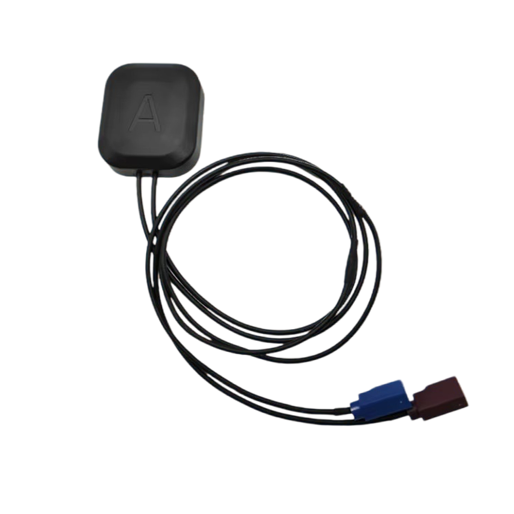
The FAKRA connector (from the German Fachkreis Automobil, or "Automobile Expert Group") is a standardized RF coaxial connector system ubiquitous in the automotive industry. It was developed to bring order to the chaos of in-vehicle connectivity, ensuring interoperability, simplifying assembly, and guaranteeing consistent RF performance in the challenging automotive environment. Its distinctive color-coded housing (typically blue for GNSS applications) and keying mechanism prevent misconnection during the vehicle manufacturing process.
The confluence of these two technologies—a high-performance antenna element and a robust, standardized interface—creates a solution that is greater than the sum of its parts. These are not mere accessories; they are the foundational sensor for any system where knowing one's exact location in real-time is paramount. The primary function of this antenna is to act as the "eyes" for the positioning engine, capturing the L-band signals (centered around 1.57542 GHz for GPS L1) and delivering them via a low-loss coaxial cable to the GNSS receiver with minimal degradation.
The demand for such high precision is driven by applications where "good enough" is not sufficient. For example, a lane-keeping system in an autonomous vehicle cannot rely on positioning that is several meters off; it requires centimeter-level accuracy to ensure the vehicle remains safely within its lane. Similarly, agricultural machinery guiding itself through a field to plant seeds or apply fertilizer must follow precise paths to maximize yield and minimize waste and environmental impact.
The operating environment for these antennas is exceptionally harsh. They must perform consistently while subjected to extreme temperatures (-40°C to +85°C is standard), constant vibration, UV radiation, moisture, salt spray, and electromagnetic interference (EMI) from the vehicle's own electronic systems. This necessitates a design philosophy that prioritizes ruggedness and reliability without compromising on electrical performance.
Furthermore, the evolution towards multi-constellation and multi-frequency (L1, L2, L5) GNSS systems has placed additional demands on antenna design. A high-precision FAKRA antenna must be a wideband or multi-band device, capable of efficiently receiving signals across a broader spectrum to leverage the advantages of modernized satellite signals, which are key to achieving high accuracy and robustness against interference and multipath.
In summary, the high-precision FAKRA GNSS antenna is a highly specialized component that sits at the very beginning of the positioning data chain. Its quality and performance directly dictate the upper limit of accuracy that the entire GNSS system can achieve. It embodies a critical compromise: delivering the cutting-edge performance required for safety-critical and precision applications through a standardized, cost-effective, and automatable interface designed for the rigors of mass production and harsh operational environments. As we move towards a more automated and data-driven world, this humble component, often unnoticed on a vehicle's roof or embedded within a device, will continue to play an outsized role in enabling the technological revolutions of tomorrow.
The exceptional performance of a high-precision FAKRA GNSS antenna is not accidental; it is the result of meticulous design and robust construction that addresses a myriad of electrical, mechanical, and environmental challenges. This section deconstructs the antenna, exploring the materials, architecture, and engineering choices that transform it from a simple passive component into a high-performance sensor.
The Radiating Element: The Heart of Performance
At the core of any antenna is its radiating element. For high-precision GNSS applications, the choice almost universally falls upon a patched antenna design. Unlike a monopole or dipole, a patch antenna consists of a flat, rectangular or circular conductive element (the patch) suspended over a larger ground plane. This structure is resonant at the target GNSS frequencies and offers several critical advantages:
Low Profile and Conformality: Their flat nature makes them ideal for integration into vehicle rooftops, dashboards, and other equipment where a low aesthetic and aerodynamic profile is required.
Controlled Radiation Pattern: They provide a directional pattern, radiating preferentially towards the sky (hemispherical or wide beamwidth) which is ideal for receiving signals from satellites above the horizon while rejecting noise and multipath reflections from the ground below.
Polarization: High-precision antennas use Circular Polarization (typically Right-Hand Circular Polarization - RHCP), as this is the polarization used by GNSS satellites. This design helps to mitigate signal degradation caused by atmospheric conditions and slight orientation shifts between the satellite and antenna, ensuring consistent signal strength.
The Multi-Layered Substrate
The patch is not mounted in free air but is fabricated onto a sophisticated printed circuit board (PCB). This PCB is a multi-layered laminate, often using materials with specific dielectric properties like Rogers RO4003 or Taconic TLY, which offer low dielectric loss and stable performance over temperature. This is crucial because any loss or instability in the substrate directly translates to reduced antenna efficiency and phase center variations—the enemy of high precision. The layers are used to create a complex feeding network, often a corporate feed or more advanced techniques, to power the radiating elements.
Achieving High Precision: Key Design Features
What separates a high-precision antenna from a standard one are several key design features:
Ground Plane: A large, stable ground plane is essential. It defines the antenna's radiation pattern, providing the necessary front-to-back ratio to reject ground reflections (multipath). In integrated designs, the vehicle's roof often acts as the ground plane.
Multipath Rejection: Advanced techniques are employed to minimize multipath—signals that bounce off the ground or nearby structures before reaching the antenna. This includes the use of EBG (Electromagnetic Band-Gap) structures or meta-materials around the periphery of the patch, which act as a high-impedance surface to suppress surface waves that cause undesired radiation.
Phase Center Stability: This is arguably the most critical parameter. The phase center is the hypothetical point from which the radiation emanates. For high-precision techniques like Real-Time Kinematic (RTK) or Precise Point Positioning (PPP), the antenna's phase center must be physically and electrically stable. Any movement of this point with signal angle, frequency, or temperature introduces error. Designers use symmetric structures and careful modeling to ensure the Phase Center Variation (PCV) is minimized and well-calibrated.
Multi-Band Operation: Modern high-precision antennas are designed to receive multiple frequencies (e.g., GPS L1, L2, L5; Galileo E1, E5a, E5b). This is achieved through sophisticated patch designs, such as stacked patches or slots, where different patches are resonant at different frequencies. This allows the receiver to correct for ionospheric delay, a major source of error.
The FAKRA Connector: The Interface Standard
The FAKRA connector is crimped or soldered to the end of a low-loss coaxial cable (often RG174 or a similar miniature cable), which is then attached to the antenna's feed point. The FAKRA system itself is a masterpiece of design-for-manufacturing:
Color-Coding and Keying: The blue housing (for GPS/GNSS) and unique mechanical keying ensure it can only be plugged into the correct port on the receiver, preventing errors on the assembly line.
Robustness: The connector is designed to withstand high vibration and repeated mating cycles.
RF Performance: It provides a consistent 50-ohm impedance match and low VSWR (Voltage Standing Wave Ratio) up to 6 GHz, more than adequate for GNSS frequencies.
Environmental Protection and Housing
The entire antenna assembly is encapsulated in a radome (housing). The material for this radome is critically important; it must be RF transparent at GNSS frequencies. Materials like polycarbonate, ABS, or ceramic-filled plastics are common. They are selected for their durability, weatherability (resistance to UV yellowing), and minimal effect on the antenna's electrical performance. The assembly is potted with epoxy or silicone to protect the delicate electronics from moisture, dust, and vibration, ensuring long-term reliability under the hood or on the roof of a vehicle.
In conclusion, the design and construction of a high-precision FAKRA GNSS antenna is a complex interplay of electromagnetic theory, materials science, and mechanical engineering. Every material, layer, and shape is optimized for a single goal: to capture pristine GNSS signals from satellites with maximum efficiency and minimum distortion, and to deliver them reliably through a standardized interface to the receiver, all while surviving the brutal conditions of its operational life.
The operation of a high-precision FAKRA GNSS antenna is a symphony of physics and engineering, translating faint electromagnetic waves from space into a precise digital location. Understanding its working principles requires moving beyond simple reception to appreciate how its design enables the complex algorithms in the receiver to achieve unparalleled accuracy.
Fundamental Signal Reception
The process begins with GNSS satellites, each transmitting spread-spectrum microwave signals on specific L-band frequencies. By the time these signals travel over 20,000 km to reach the Earth's surface, their power is astonishingly low, often described as being "below the noise floor." The primary job of the antenna is to act as a "collector" for this energy. Its physical aperture and efficient design provide gain, effectively amplifying the desired signals from specific directions (the sky) relative to the omnipresent thermal noise.
The Criticality of Circular Polarization
GNSS signals are transmitted using Right-Hand Circular Polarization (RHCP). A high-precision antenna is specifically designed to be sensitive only to RHCP waves. This offers a significant advantage: signals that reflect off surfaces (like the ground or buildings) undergo a polarization shift, typically becoming Left-Hand Circular Polarized (LHCP). The antenna is inherently less receptive to these reflected LHCP signals. This property is the first and most crucial line of defense against multipath error—a phenomenon where the receiver confuses a delayed reflected signal for a direct one, leading to large positioning errors.
Bandwidth and Multi-Frequency Operation
A standard antenna might only be tuned for the primary L1 frequency (1575.42 MHz). A high-precision antenna, however, is a wideband or multi-resonant device. It must simultaneously and efficiently receive signals on L1, L2 (1227.60 MHz), and L5 (1176.45 MHz) with consistent performance. This capability is non-negotiable for high-precision positioning. The receiver uses the slight delay between these different frequencies to calculate and correct for the ionospheric delay—the slowing of the signal as it passes through the charged particles of the ionosphere, which is the largest source of error in standard GNSS.
Phase Center Stability: The Cornerstone of Precision
The ultimate goal of systems like Real-Time Kinematic (RTK) is to measure the carrier phase of the signal, not just the code. The wavelength of the GPS L1 carrier signal is only about 19 cm. By measuring the phase of this carrier wave to a fraction of a wavelength, centimeter-level accuracy becomes possible.
The antenna's Phase Center is the virtual point from which this signal appears to originate. For these phase measurements to be valid, the phase center must not move. If it shifts when the satellite moves across the sky (azimuth and elevation) or when the temperature changes, it introduces a measurement error that mimics a physical movement of the antenna.
High-precision antennas are meticulously designed to have an extremely stable and well-defined phase center across all angles, frequencies, and temperatures. Manufacturers provide detailed calibration tables (ANTEX files) that map the precise phase center variations (PCV) for their antennas. The receiver uses these tables to correct the raw measurements, eliminating this source of error before the positioning calculation even begins.
The Role of the Ground Plane and Radiation Pattern
The antenna's radiation pattern is sculpted to maximize gain towards the horizon and slightly above it (where most satellites are located) and to minimize gain (nulls) towards the ground. This high front-to-back ratio further suppresses multipath signals arriving from below the antenna. The ground plane is essential in creating this pattern. In a vehicle-mounted antenna, the car's metal roof becomes an integral part of this system, and the antenna is designed with this in mind.
The Path to the Receiver
Once the antenna has captured the signals, its task is to deliver them to the GNSS receiver with minimal loss and distortion. This is where the coaxial cable and the FAKRA connector play their part.
The low-loss coaxial cable is chosen to preserve the weak signal strength. Longer cables have more loss, which degrades the signal-to-noise ratio (SNR), so a balance must be struck between installation flexibility and performance.
The FAKRA connector ensures a perfect 50-ohm impedance match at the interface. Any impedance mismatch causes a portion of the signal to be reflected back towards the antenna (measured as VSWR), reducing power transfer and potentially distorting the signal. The FAKRA standard guarantees a consistent, high-quality connection that maintains the integrity of the signal chain.
In essence, the working principle of a high-precision antenna is not passive; it is an active and critical participant in the measurement process. It doesn't just "hear" the satellites; it carefully curates the signals, rejecting noise and multipath, presenting a clean, stable, and multi-frequency set of data to the receiver. It provides the high-quality "raw material"—the carrier phase measurements—that the receiver's sophisticated algorithms then use to resolve integer ambiguities and compute a position with centimeter-level certainty. The antenna's stability and predictability are what make this complex mathematical process possible.
The adoption of high-precision FAKRA GNSS antennas brings a host of significant benefits but also introduces a set of unique challenges that designers and system integrators must navigate. Understanding these dualities is key to successfully implementing them in real-world applications.
Advantages
Standardization and Interoperability (The FAKRA Advantage): The single greatest advantage is the FAKRA connector itself. It eliminates guesswork and compatibility issues during manufacturing. An OEM can source antennas from multiple qualified suppliers confident that they will physically and electrically interface with their standardized receiver ports. This simplifies the supply chain, reduces assembly errors, and lowers overall costs through economies of scale and competition.
Unmatched Accuracy and Reliability: The core purpose of these antennas is delivered superbly. Their design—featuring stable phase centers, multipath rejection, and multi-frequency support—enables positioning technologies like RTK and PPP. This provides centimeter-level accuracy, which is a fundamental requirement for autonomous driving, precision guidance, and surveying, where safety and efficiency depend on it.
Ruggedness and Environmental Resilience: These components are engineered from the ground up for harsh environments. They are built to withstand extreme automotive and industrial conditions: temperature cycling, humidity, salt fog, UV exposure, and constant mechanical vibration and shock. This high level of robustness ensures long-term reliability and reduces the total cost of ownership by minimizing failures and maintenance.
Optimized for Automotive Integration: The combination of a low-profile form factor and the FAKRA connector makes them ideal for vehicles. They can be seamlessly integrated into roof modules, shark-fin assemblies, or dashboards without requiring custom wiring harnesses or connectors, streamlining the design process for automotive engineers.
Future-Proofing through Multi-Band Support: High-quality antennas designed for L1/L2/L5 are ready for the ongoing modernization of GNSS constellations. As new signals like GPS L5 and Galileo E5 become fully operational, they offer improved accuracy, better interference resistance, and faster integer ambiguity resolution for RTK. Systems equipped with these advanced antennas can leverage these new signals without requiring a hardware retrofit.
Challenges
Cost and Complexity: High-precision is not cheap. The use of specialized low-loss PCB materials (Rogers, Taconic), complex multi-layer patch designs, rigorous testing, and environmental sealing significantly increases the manufacturing cost compared to a simple ceramic patch antenna with an SMA connector. This can be a barrier to entry for cost-sensitive applications.
Calibration and Phase Center Variability: While these antennas are designed for stability, minute phase center variations (PCV) still exist. For the highest levels of accuracy (e.g., geodetic survey), these variations must be meticulously measured in an anechoic chamber for each antenna model. The resulting calibration data must then be used by the receiver software. This adds a layer of complexity to the system integration process, as using an antenna without its proper PCV table can introduce unnoticed errors.
Integration and Ground Plane Dependency: The performance of a patch antenna is heavily influenced by its ground plane. While designed to work with a vehicle's roof, the actual performance can vary depending on the specific size, shape, and curvature of the metal surface it is mounted on. Installing it on a non-ideal surface (e.g., a composite material or a small ground plane) can distort its radiation pattern, degrade its multipath rejection, and destabilize its phase center, nullifying its high-precision capabilities. This demands careful installation planning.
Cable Loss and System Design: The weak GNSS signals are vulnerable to attenuation in the coaxial cable. Longer cable runs (e.g., from a roof antenna to a receiver in the trunk) can significantly degrade the Signal-to-Noise Ratio (SNR). While active antennas with integrated Low-Noise Amplifiers (LNAs) combat this, they require a power supply (often provided via coaxial cable bias). Integrators must carefully calculate the system's link budget, balancing cable length, type, LNA gain, and receiver performance.
Electromagnetic Interference (EMI): The automotive environment is electrically noisy, with sources of EMI from motors, inverters, infotainment systems, and other electronic control units (ECUs). Despite shielding, this noise can couple onto the cable or directly interfere with the antenna. High-precision antennas must have excellent out-of-band rejection to filter out this noise, and the entire system requires careful EMI/EMC design to prevent self-jamming of the critically sensitive GNSS band.
In conclusion, the advantages of high-precision FAKRA antennas—standardization, accuracy, and ruggedness—make them the unequivocal choice for professional and automotive applications. However, these benefits come with the challenges of higher cost, integration complexity, and a need for expert calibration and system design. Successfully leveraging these components requires a holistic view of the entire GNSS system, from the antenna's physical installation to the receiver's software configuration.
The unique capabilities of high-precision FAKRA GNSS antennas have unlocked a vast array of applications that were once impractical or impossible. Furthermore, ongoing trends in technology are continuously expanding their role and shaping their future evolution.
Current Applications
Automotive and Autonomous Driving (ADAS): This is the primary domain. These antennas are critical for:
Advanced Driver-Assistance Systems (ADAS): Enabling lane-level accuracy for features like lane departure warning and adaptive cruise control.
Autonomous Vehicle (AV) Navigation: Providing the absolute positioning required for path planning and decision-making in self-driving cars, often fused with LiDAR, radar, and IMU data.
V2X (Vehicle-to-Everything) Communication: For safety applications like collision avoidance, precise location is essential for V2X messages to be meaningful.
eCall and Telematics: Providing accurate location in the event of an accident and for fleet management and stolen vehicle recovery.
Precision Agriculture: Revolutionizing farming by enabling:
Auto-Guidance: Allowing tractors and harvesters to drive themselves with centimeter accuracy, eliminating overlaps and gaps in planting, spraying, and harvesting. This saves fuel, time, seeds, and fertilizer.
Variable Rate Application (VRA): Using precise location to apply water, fertilizers, and pesticides only where needed, based on soil data maps, boosting efficiency and sustainability.
Unmanned Aerial Vehicles (UAVs) and Drones: Essential for:
Precision Navigation: Allowing drones to hold a stable hover and follow pre-programmed flight paths accurately for applications like aerial surveying, mapping, and infrastructure inspection.
Photogrammetry and LiDAR Mapping: When coupled with RTK, the drone's position is known precisely, allowing it to create highly accurate 3D models and maps without the need for numerous ground control points.
Geomatics and Surveying: While traditionally using geodetic antennas with tribrach mounts, the ruggedness and improving performance of automotive-grade antennas are finding use in:
Construction Machine Control: Guiding bulldozers, graders, and excavators to achieve design grades without stakes, significantly speeding up earthworks.
Mobile Mapping Systems: Mounted on vehicles or backpacks to quickly and accurately map infrastructure, roads, and urban environments.
Marine and Robotics: Used for precise navigation of autonomous surface vessels, underwater vehicles, and a wide variety of mobile robots in logistics and industrial settings.
Future Trends
Deep Integration with "Sensor Fusion": The antenna will increasingly be treated not as a standalone component but as a core sensor in a fused system. Future modules will co-package the antenna with an IMU (Inertial Measurement Unit), a dedicated GNSS receiver chip, and perhaps even other sensors, providing a pre-processed, robust "positioning engine" output over a CAN or Ethernet interface, rather than raw RF signals.
The Rise of Multi-Band, Multi-Constellation as Standard: Support for all signals from GPS, Galileo, GLONASS, and BeiDou across L1, L2, and L5 bands will become the baseline expectation. This "constellation redundancy" provides robustness in challenging urban canyons and ensures continuous high accuracy globally.
Anti-Jamming and Anti-Spoofing (AJA): As society becomes more dependent on GNSS, its vulnerability to intentional jamming (blocking signals) and spoofing (broadcasting fake signals) becomes a critical security risk. Future high-precision antennas will integrate controlled radiation pattern arrays (CRPAs) or null-steering techniques to automatically null out interference sources, making systems resilient to attack.
Miniaturization and "Antenna-in-Package" Solutions: The drive for smaller, more integrated designs will continue. We will see more "antenna-in-package" solutions where the radiating element is integrated directly into a module alongside other electronics, though this will present significant challenges for maintaining phase center stability and performance.
Enhanced Cybersecurity for Positioning Data: With the antenna and receiver being a critical entry point for spoofing attacks, future trends will include hardware-level security features and cryptographic authentication of satellite signals to ensure the received data is genuine and trustworthy.
The high-precision FAKRA GNSS antenna, therefore, is not a static technology. It is a dynamically evolving field, driven by the demanding requirements of autonomous systems and the need for resilient, trustworthy positioning. Its future lies in deeper integration, greater intelligence, and enhanced security, solidifying its role as the bedrock of the positioning ecosystem.
Conclusion
In the intricate and invisible process of determining one's precise location on Earth, the high-precision FAKRA GNSS antenna stands as the indispensable and foundational link in the data chain. It is the critical gateway through which all positioning information must first pass. As we have explored, this component is far more than a simple piece of metal designed to capture radio waves; it is a highly sophisticated transducer, meticulously engineered to address a profound set of electrical, environmental, and practical challenges.
Its significance is twofold. First, from a performance perspective, it is the key enabler of centimeter-level accuracy. Through its stable phase center, rejection of multipath signals, support for multiple frequencies, and resilience against environmental degradation, it provides the high-fidelity signal data that advanced algorithms like RTK and PPP require to function. Without this quality of input, the most powerful receiver in the world would be severely limited in its output. The antenna sets the ceiling for the entire system's potential accuracy.
Second, from an industrial and integration perspective, the FAKRA connector embodies the principle of standardized performance. It bridges the gap between the bespoke world of high-performance RF design and the brutal economics and logistics of automotive mass production. It ensures reliability, interoperability, and simplicity in manufacturing, allowing this cutting-edge technology to be deployed reliably millions of times over across global vehicle platforms.
The applications that depend on this technology—from autonomous vehicles that must perceive their world with absolute certainty to agricultural systems that optimize our use of the planet's resources—are at the forefront of a technological revolution aimed at enhancing safety, efficiency, and sustainability. The humble antenna, often hidden from view, is a silent hero in this revolution.
Looking ahead, the role of the high-precision antenna will only grow in importance. As trends like sensor fusion, anti-jamming capabilities, and deeper integration continue, the antenna will evolve from a passive component into an intelligent, active subsystem. The challenges of cost, calibration, and integration will persist, driving innovation towards more elegant and robust solutions.
In conclusion, the high-precision FAKRA GNSS antenna is a paradigm of modern engineering: a device that solves complex physical problems while seamlessly integrating into standardized industrial ecosystems. It is a testament to the fact that true technological advancement often depends as much on the perfection of fundamental components like antennas and connectors as it does on the power of software and processing. As we navigate towards a more automated and spatially-aware future, this component will remain, quietly and reliably, our unwavering connection to the constellations above.

 86 0755 2819 9597
Lucy Yang | lucy.y@toxutech.com
Nicole Li | nicole@toxutech.com
Dotty Zhao | sales04@toxutech.com
Global Business Director / Sales Team / Global Operations


 En
En Cn
Cn Korean
 Home >


