

-
Products -PCBA Manufacturing RF Connectors RF Cable Assemblys Embedded Antennas External Antennas Positioning Chips and Modules
RF Connectors

RF Cable Assemblys
Embedded Antennas
External Antennas
Positioning Chips and Modules


 Language


Language


In the era of precise positioning and location-based services, the demand for high-accuracy positioning technology has surged across industries ranging from agriculture and construction to autonomous vehicles and geospatial mapping. Among the key technologies driving this demand, the Global Navigation Satellite System (GNSS) has emerged as a foundational tool, providing global coverage for positioning, navigation, and timing (PNT) services. However, standard GNSS solutions often fall short of meeting the strict accuracy requirements of modern applications, where centimeter-level or even millimeter-level precision is essential. This is where Real-Time Kinematic (RTK) technology comes into play, and when integrated into a built-in antenna module, it creates a powerful solution known as the high accuracy built-in GNSS RTK antenna module.
To understand the significance of this module, it is first necessary to break down its core components and their roles. GNSS itself encompasses a suite of satellite constellations, including the United States’ GPS, Russia’s GLONASS, the European Union’s Galileo, and China’s BeiDou. These constellations transmit signals that are received by GNSS antennas, which then forward the data to a receiver for processing. Standard GNSS receivers typically achieve positioning accuracy in the range of 1-10 meters, which is sufficient for applications like general navigation but inadequate for tasks such as precision agriculture (where seed planting or fertilizer application requires sub-meter accuracy) or construction (where structural alignment demands centimeter-level precision).
RTK technology addresses this limitation by leveraging a network of fixed, reference stations that are precisely surveyed to known locations. These reference stations receive the same GNSS signals as the user’s receiver (equipped with the RTK module) and calculate the difference between the measured position and the true, known position. This difference, known as the differential correction, is then transmitted to the user’s module in real time. By applying these corrections to the raw GNSS data, the module can achieve positioning accuracy ranging from 1 centimeter to 1 meter, depending on factors like the distance from the reference station, signal quality, and environmental conditions.
The “built-in” aspect of the module is another critical feature that distinguishes it from external RTK systems. Traditional RTK setups often require separate antennas, receivers, and correction devices, which can be bulky, expensive, and difficult to integrate into compact devices. In contrast, a built-in GNSS RTK antenna module combines the antenna, receiver, and correction processing capabilities into a single, miniaturized unit that can be embedded directly into end-user devices such as smartphones, drones, wearable trackers, or industrial sensors. This integration not only reduces the size and weight of the device but also lowers power consumption and simplifies the overall system design, making high-accuracy positioning accessible to a wider range of applications.
The development of high accuracy built-in GNSS RTK antenna modules has been driven by several key trends in technology and industry demand. First, the expansion of GNSS constellations has improved signal availability and redundancy. For example, the completion of Galileo’s full constellation and the ongoing expansion of BeiDou have increased the number of satellites in orbit, ensuring that receivers can pick up signals even in challenging environments like urban canyons or dense forests. Second, advances in semiconductor technology have enabled the development of smaller, more powerful receivers that can process multiple GNSS signals simultaneously and handle the complex calculations required for RTK corrections. Third, the growth of industries like precision agriculture, autonomous driving, and drone mapping has created a urgent need for compact, high-accuracy positioning solutions that can be integrated into existing devices.
From a market perspective, the global market for GNSS RTK modules is expected to grow significantly in the coming years. According to industry reports, the market size was valued at over \(2 billion in 2023 and is projected to exceed \)5 billion by 2030, with a compound annual growth rate (CAGR) of around 12%. This growth is fueled by increasing adoption in sectors like agriculture (where precision farming techniques reduce costs and improve yields), construction (where RTK-enabled equipment enhances productivity and safety), and automotive (where autonomous vehicles rely on high-accuracy positioning for navigation and collision avoidance).
It is also important to note the role of regulatory and standards bodies in shaping the development of these modules. Organizations like the International Civil Aviation Organization (ICAO) and the International Electrotechnical Commission (IEC) have established standards for GNSS performance and safety, ensuring that RTK modules meet strict requirements for reliability and accuracy. Additionally, regional initiatives such as the European Geostationary Navigation Overlay Service (EGNOS) and the U.S. Wide Area Augmentation System (WAAS) provide additional correction signals that complement RTK technology, further improving positioning accuracy and availability.
In summary, the high accuracy built-in GNSS RTK antenna module represents a convergence of GNSS and RTK technologies, packaged in a compact, integrated form factor. It addresses the limitations of standard GNSS solutions by providing real-time differential corrections, enabling centimeter-level accuracy, and its built-in design makes it suitable for integration into a wide range of devices. As technology continues to advance and industry demand grows, this module is poised to become a key enabler of the next generation of location-based services and precision applications.
The design and construction of a high accuracy built-in GNSS RTK antenna module are complex processes that require careful consideration of multiple factors, including signal reception, noise reduction, power efficiency, miniaturization, and integration with other device components. Each element of the module—from the antenna itself to the receiver circuitry and correction processing unit—must be optimized to work together seamlessly to deliver reliable, high-accuracy positioning. This section will break down the key components of the module and explore the design principles and construction techniques that ensure its performance.
2.1 Antenna Design: The Foundation of Signal Reception
The antenna is the first and most critical component of the GNSS RTK module, as its ability to receive weak GNSS signals directly impacts the module’s overall accuracy. For built-in modules, the antenna must be compact enough to fit within the constraints of small devices (such as smartphones or drones) while still providing high gain, low noise, and wide bandwidth to capture signals from multiple GNSS constellations.
There are several common types of antennas used in GNSS RTK modules, each with its own design characteristics:
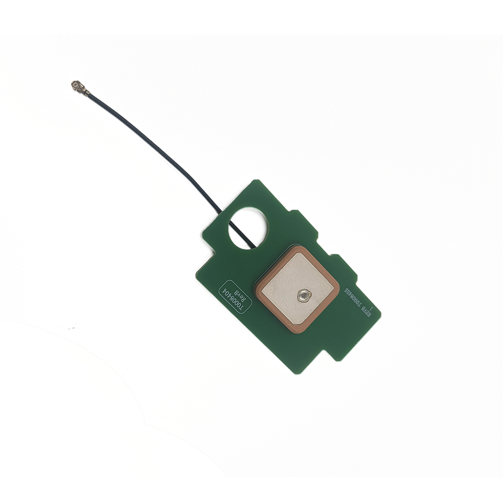
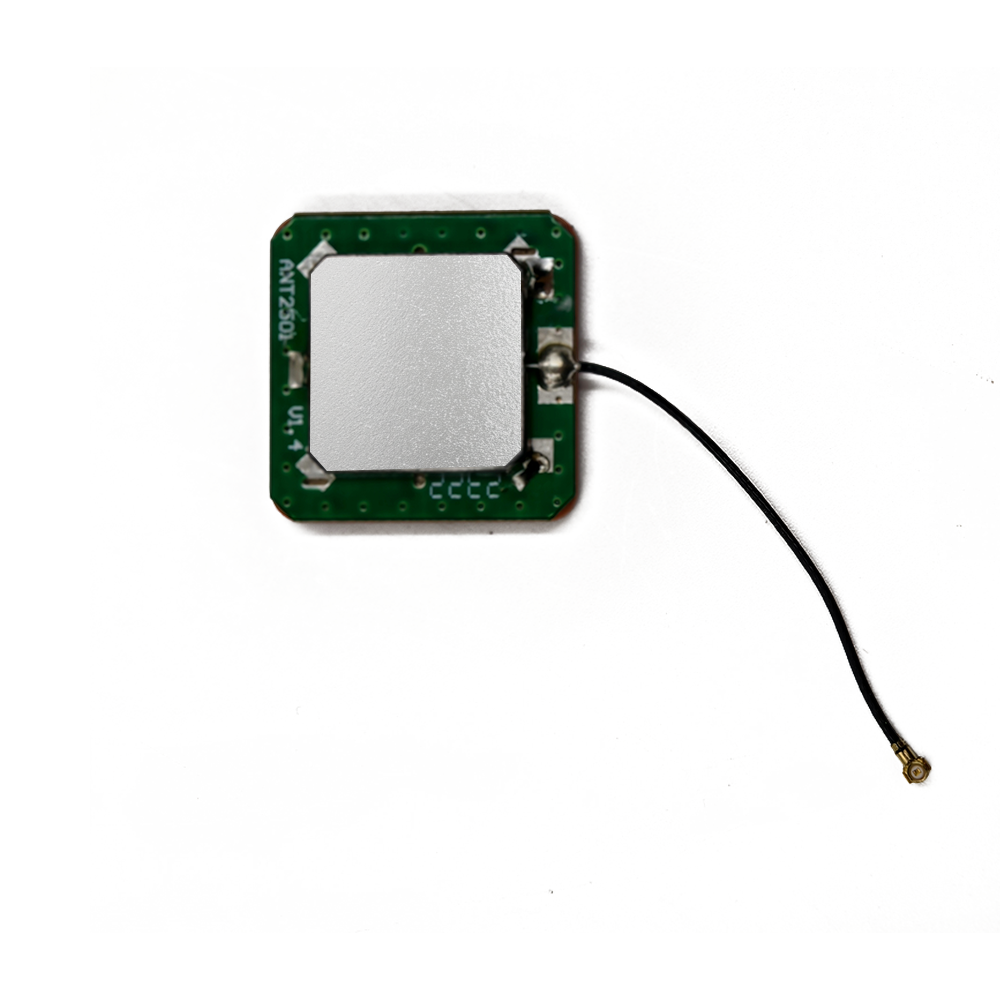
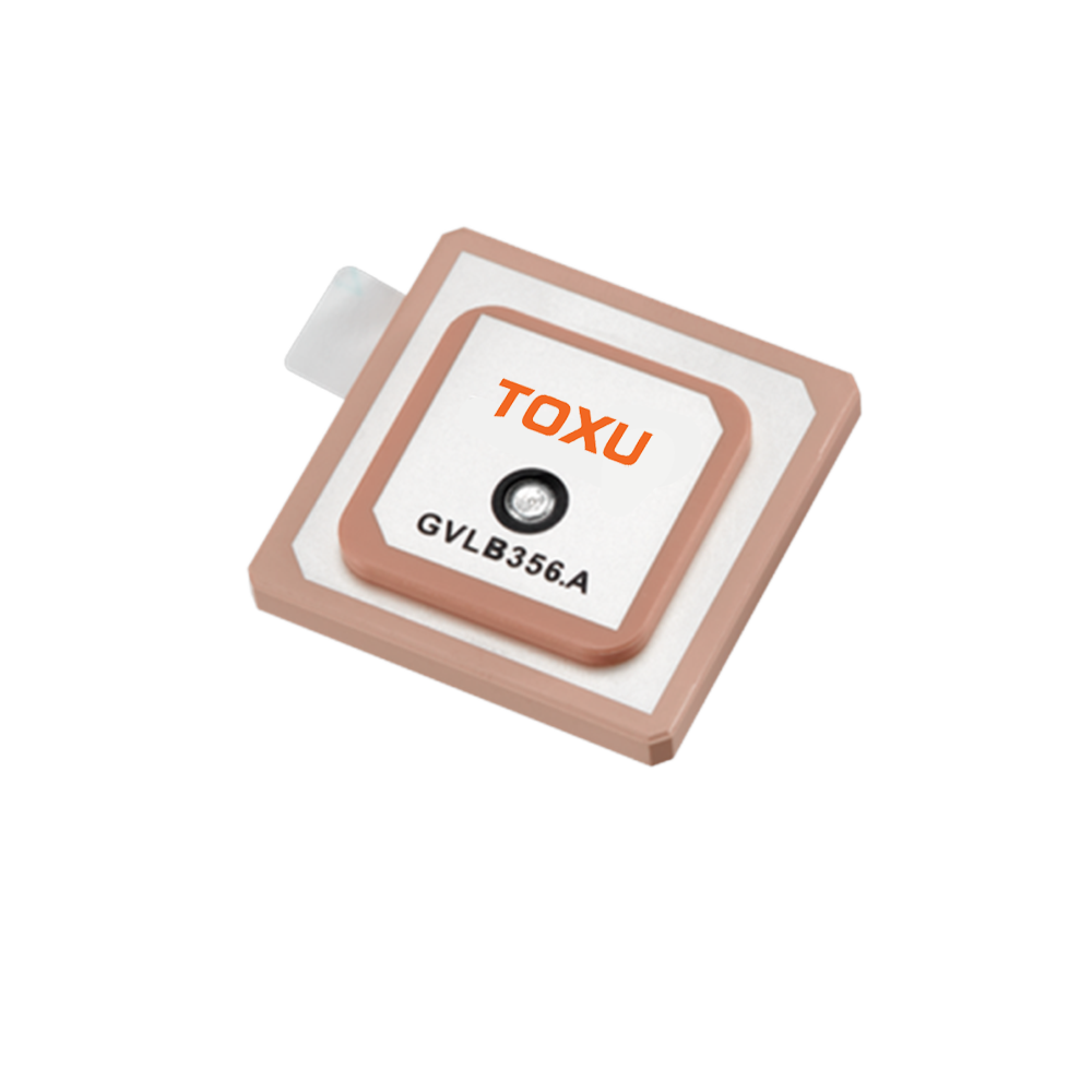
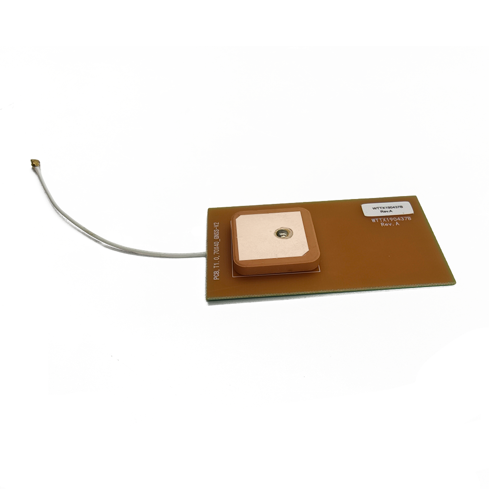
Patch Antennas: The most widely used type in built-in modules, patch antennas consist of a flat, conductive patch (usually made of copper) mounted on a dielectric substrate (such as FR4 or Rogers material) above a ground plane. They are lightweight, low-profile, and can be easily integrated into small devices. Patch antennas are designed to operate at specific frequency bands (e.g., L1, L2, L5 for GPS), and their gain (typically 2-5 dBi) and radiation pattern (hemispherical) are optimized for receiving signals from satellites in the sky. To support multiple GNSS constellations, dual-band or multi-band patch antennas are often used, which can receive signals at multiple frequency bands simultaneously (e.g., L1 and L5 for GPS, E1 for Galileo, B1 for BeiDou).
Helical Antennas: While less common in built-in modules due to their larger size, helical antennas offer higher gain (up to 10 dBi) and a more directional radiation pattern, making them suitable for applications where signal reception is challenging (e.g., in urban canyons). However, their cylindrical shape and larger volume make them less ideal for compact devices, so they are typically used in external RTK systems or larger devices like industrial sensors.
Choke Ring Antennas: These antennas are designed to minimize multipath interference, a major source of error in GNSS positioning. Multipath occurs when GNSS signals reflect off surfaces like buildings, trees, or water before reaching the antenna, leading to delayed signals and inaccurate position calculations. Choke ring antennas consist of a central patch antenna surrounded by a series of concentric rings (chokes) that absorb reflected signals, reducing multipath errors. While highly effective, choke ring antennas are large and heavy, so they are primarily used in fixed reference stations rather than built-in modules.
In addition to the antenna type, the design must also consider factors like polarization and impedance matching. GNSS signals are linearly polarized, so the antenna must be oriented to match the polarization of the incoming signals (usually vertical or horizontal) to maximize signal reception. Impedance matching (typically 50 ohms) ensures that the signal is efficiently transferred from the antenna to the receiver, minimizing signal loss.
2.2 Receiver Circuitry: Processing Raw GNSS Data
The receiver circuitry is responsible for amplifying the weak GNSS signals received by the antenna, converting them from analog to digital format, and extracting the raw data (such as satellite ephemeris, pseudoranges, and carrier phase measurements) needed for positioning. For RTK modules, the receiver must be capable of processing carrier phase measurements with high precision, as RTK relies on these measurements (rather than just pseudoranges) to achieve centimeter-level accuracy.
Key components of the receiver circuitry include:
Low-Noise Amplifier (LNA): The LNA is the first component in the receiver chain, and its role is to amplify the weak GNSS signals (which can be as low as -160 dBm) while adding minimal noise. A high-performance LNA (with a noise figure of less than 1 dB) is critical, as any noise introduced here will degrade the signal quality and reduce the module’s accuracy. LNAs are often designed to operate at specific frequency bands (matching the antenna’s bandwidth) and are integrated into the antenna module to minimize signal loss between the antenna and the LNA.
Downconverter: After amplification, the signals are passed to a downconverter, which converts the high-frequency GNSS signals (e.g., 1.575 GHz for GPS L1) to a lower intermediate frequency (IF) that is easier to process. This conversion is typically done using a local oscillator (LO) and a mixer, which multiplies the input signal with the LO signal to produce the IF signal.
Analog-to-Digital Converter (ADC): The IF signal is then converted from an analog signal to a digital signal by the ADC. The ADC’s resolution (measured in bits) and sampling rate are critical factors—higher resolution (e.g., 12-16 bits) ensures that small variations in the signal are captured, while a high sampling rate (e.g., 10-100 MHz) allows the receiver to process multiple signals simultaneously.
Baseband Processor: The digital signal is then sent to the baseband processor, which performs signal demodulation, decoding, and measurement extraction. For RTK modules, the baseband processor must be capable of tracking the carrier phase of the GNSS signals with high precision. Carrier phase measurements track the phase of the satellite’s carrier signal (e.g., 1575.42 MHz for GPS L1), which has a much shorter wavelength (about 19 cm for L1) than the pseudorange (which is based on the code signal with a wavelength of about 300 meters). This shorter wavelength allows for much higher accuracy in position calculations. The baseband processor also decodes the satellite’s navigation message, which contains information about the satellite’s orbit (ephemeris) and clock corrections, which are essential for calculating the satellite’s position and the user’s position.
2.3 RTK Correction Processing Unit: Enabling High Accuracy
The RTK correction processing unit is the heart of the module, as it is responsible for receiving differential corrections from a reference station, processing these corrections, and applying them to the raw GNSS data to calculate the user’s precise position.
2.3.1 Correction Data Reception
The module can receive correction data via several communication channels, including:
Radio Frequency (RF): Many RTK modules use dedicated RF channels (e.g., UHF or VHF) to receive corrections from nearby reference stations. This is common in applications like agriculture or construction, where a local network of reference stations is deployed.
Cellular Networks: With the growth of 4G and 5G networks, many modern RTK modules use cellular data (e.g., LTE, 5G) to receive corrections from a wide-area RTK (WARTK) network. WARTK networks consist of a large number of reference stations distributed over a wide area (e.g., a country or region), and the correction data is processed at a central server and transmitted to users via cellular networks. This approach offers wider coverage and eliminates the need for a local reference station.
Satellite Communication: In remote areas where cellular coverage is unavailable, some modules use satellite communication (e.g., via Iridium or Globalstar) to receive correction data. However, this is less common due to higher costs and slower data rates.
The correction data typically includes information like the reference station’s known position, the measured pseudoranges and carrier phases at the reference station, and the atmospheric corrections (ionospheric and tropospheric) that affect signal propagation.
2.3.2 Correction Processing and Position Calculation
Once the correction data is received, the processing unit performs several key steps:
Data Synchronization: The module synchronizes the user’s GNSS measurements with the reference station’s measurements to ensure that they are taken at the same time (or as close as possible). This is critical because the satellite positions and atmospheric conditions change over time, so unsynchronized measurements can lead to errors.
Differential Correction Calculation: The processing unit calculates the difference between the user’s measurements and the reference station’s measurements. For example, if the reference station measures a pseudorange of 20,000 km to a satellite, but the true pseudorange (based on the reference station’s known position) is 19,999.99 km, the correction for that satellite is -0.01 km. This correction is then applied to the user’s pseudorange measurement to reduce errors caused by atmospheric conditions, satellite clock errors, and other common errors.
Carrier Phase Ambiguity Resolution: One of the key challenges in RTK technology is resolving the carrier phase ambiguity. The carrier phase measurement is the fraction of the carrier wavelength that the signal has traveled from the satellite to the receiver, but the receiver does not know the integer number of wavelengths (the ambiguity) that the signal has traveled. Resolving this ambiguity is essential for achieving centimeter-level accuracy. There are several algorithms used for ambiguity resolution, including the Least Squares Ambiguity Decorrelation Adjustment (LAMBDA) method and the Integer Gauss Transformation (IGT) method. These algorithms use statistical techniques to determine the most likely integer value for the ambiguity, based on the carrier phase measurements from multiple satellites.
Position Calculation: Once the ambiguities are resolved and the corrections are applied, the processing unit calculates the user’s position using the corrected carrier phase measurements. The position is typically expressed in a global coordinate system (e.g., WGS84) or a local coordinate system (e.g., UTM) depending on the application.
2.4 Miniaturization and Integration: Key Design Challenges
One of the biggest challenges in designing a built-in GNSS RTK antenna module is miniaturization. The module must fit into small devices like smartphones or drones, which have limited space, so every component must be as small as possible. This requires the use of advanced packaging technologies, such as System-in-Package (SiP) or Chip-on-Board (COB) packaging, which integrate multiple components (e.g., the antenna, LNA, receiver, and processing unit) into a single, compact package.
Another challenge is power efficiency. Built-in modules are often used in battery-powered devices, so they must consume minimal power to extend the device’s battery life. This is achieved by optimizing the receiver circuitry (e.g., using low-power LNAs and ADCs), implementing power management techniques (e.g., turning off unused components when not in use), and using efficient correction data transmission methods (e.g., compressing correction data to reduce data transfer time).
Thermal management is also an important consideration. The receiver circuitry and processing unit generate heat during operation, which can degrade performance if not properly managed. In built-in modules, this is typically addressed by using heat sinks, thermal vias, or low-power components that generate less heat. Additionally, the module’s placement within the device is optimized to ensure that it is not exposed to excessive heat from other components (e.g., the device’s processor).
Finally, the module must be designed to be compatible with the device’s other components and communication interfaces. For example, it may need to communicate with the device’s main processor via interfaces like SPI, I2C, or UART, and it may need to integrate with the device’s power management system. This requires careful design of the module’s electrical interfaces and software drivers to ensure seamless integration.
In conclusion, the design and construction of a high accuracy built-in GNSS RTK antenna module require a holistic approach that optimizes each component—from the antenna to the receiver circuitry and correction processing unit—for performance, miniaturization, power efficiency, and integration. By addressing the challenges of signal reception, noise reduction, and thermal management, these modules can deliver the centimeter-level accuracy needed for modern precision applications.
To fully grasp the capabilities of a high accuracy built-in GNSS RTK antenna module, it is essential to understand the underlying working principles that enable it to achieve centimeter-level positioning accuracy. Unlike standard GNSS modules, which rely solely on raw satellite signals to calculate position, RTK modules leverage a combination of raw GNSS data and real-time differential corrections from reference stations to eliminate common errors. This section will break down the working principles of the module into key stages: signal reception and initial processing, reference station operation, differential correction generation and transmission, ambiguity resolution, and final position calculation.
3.1 Stage 1: GNSS Signal Reception and Initial Processing
The first step in the module’s operation begins with the reception of GNSS signals from satellites in orbit. As discussed in the design section, the module’s built-in antenna (typically a multi-band patch antenna) captures signals from multiple GNSS constellations (e.g., GPS, Galileo, BeiDou) operating at different frequency bands (e.g., L1, L2, L5). These signals are extremely weak—often as low as-160 dBm, equivalent to a few photons per second—so the first stage of processing focuses on amplifying the signal while minimizing noise interference.
The low-noise amplifier (LNA) integrated with the antenna is critical here. It boosts the weak signals by 20-40 dB (decibels) while adding a noise figure of less than 1 dB, ensuring that the signal-to-noise ratio (SNR) remains high. Any noise introduced at this stage would be amplified along with the signal, degrading the quality of subsequent measurements, so LNAs are designed with high linearity and low noise components (such as gallium arsenide or silicon germanium transistors) to maintain signal integrity.
After amplification, the signals are passed to the downconverter, which reduces the high-frequency GNSS signals (e.g., 1.575 GHz for GPS L1, 1.227 GHz for GPS L2) to a lower intermediate frequency (IF)—typically between 10 MHz and 100 MHz. This conversion simplifies signal processing, as lower-frequency signals are easier to handle with digital circuits and require less bandwidth for analog-to-digital conversion. The downconverter uses a local oscillator (LO) to generate a signal that is mixed with the incoming GNSS signal; the resulting IF signal retains the phase and amplitude information of the original GNSS signal, which is essential for later measurements.
Next, the analog IF signal is converted to a digital signal by the analog-to-digital converter (ADC). The ADC’s performance directly impacts the precision of the module: a 12- to 16-bit resolution ensures that small variations in the signal (down to a few microvolts) are captured, while a sampling rate of 10-100 MHz allows the receiver to process multiple satellite signals simultaneously. For RTK modules, which rely on carrier phase measurements, the ADC must also have low jitter (timing uncertainty) to avoid introducing errors in phase tracking.
The digital signal is then sent to the baseband processor, which performs two key tasks: demodulating the signal to extract the navigation message, and tracking the code and carrier phase of the signal. The navigation message contains critical information about the satellite’s orbit (ephemeris data), clock offsets relative to GPS time, and atmospheric correction parameters (ionospheric and tropospheric models). This data is decoded and stored in the module’s memory for use in position calculations.
Code tracking involves locking onto the pseudorandom noise (PRN) code embedded in the GNSS signal. Each satellite transmits a unique PRN code, which allows the receiver to distinguish between signals from different satellites. The baseband processor uses a code correlator to align a local copy of the PRN code with the received code; the time delay between the two codes (known as the code phase) is used to calculate the pseudorange—the approximate distance between the satellite and the receiver. Pseudoranges are relatively easy to measure but have errors of several meters due to atmospheric delays, satellite clock errors, and multipath interference.
For RTK, however, the critical measurement is the carrier phase. The carrier phase is the fraction of the carrier wave’s wavelength that the signal has traveled from the satellite to the receiver. For example, the GPS L1 carrier has a wavelength of ~19 cm, so measuring the carrier phase with a precision of 1% of the wavelength would yield a position error of just ~1.9 mm. The baseband processor uses a phase-locked loop (PLL) to track the carrier phase, which requires maintaining a stable lock on the signal. If the signal is blocked (e.g., by a building or tree), the PLL may lose lock, and the module must re-acquire the signal—a process that can take several seconds.
3.2 Stage 2: Reference Station Operation
The second key component of the RTK system is the reference station—a fixed, ground-based receiver that is installed at a precisely surveyed location (known as the “true position”). Reference stations are critical because they provide a baseline for calculating differential corrections; by comparing their own measured position (derived from GNSS signals) to their known true position, they can quantify the errors present in the GNSS signals and transmit these error corrections to the user’s module.
3.2.1 Reference Station Setup and Calibration
Before a reference station can be used, its true position must be determined with extreme precision—typically at the millimeter level. This is done through a process called “static surveying,” where the reference station collects GNSS data for several hours (or even days) and processes it with data from other nearby reference stations (part of a national or regional GNSS network, such as the U.S. National CORS Network or the European EGNOS network). The static surveying process averages out short-term errors (e.g., multipath, satellite clock fluctuations) and uses advanced algorithms to calculate the reference station’s position in a global coordinate system (e.g., WGS84) or a local coordinate system (e.g., NAD83 for North America).
Once the true position is known, the reference station is configured to continuously receive GNSS signals and calculate its “measured position” using the same code and carrier phase measurements as the user’s module. The difference between the measured position and the true position is the “error vector,” which includes contributions from:
Ionospheric delay: The ionosphere (a layer of charged particles in the upper atmosphere) slows down GNSS signals, introducing delays that vary with time of day, solar activity, and geographic location.
Tropospheric delay: The troposphere (the lower atmosphere) also delays GNSS signals, with delays increasing in humid or cold conditions.
Satellite clock errors: Small inaccuracies in the satellite’s onboard atomic clock can cause errors in pseudorange and carrier phase measurements.
Orbit errors: Even with precise ephemeris data, there may be small errors in the satellite’s calculated orbit due to gravitational perturbations from the moon, sun, or other celestial bodies.
Multipath interference: Reflected signals can cause errors in both code and carrier phase measurements, though reference stations are often installed in open areas (e.g., on top of buildings or in fields) to minimize this.
3.2.2 Correction Data Generation
The reference station processes its measured code and carrier phase data in real time to generate two types of correction data:
Code corrections: These correct the errors in the pseudorange measurements. Code corrections are relatively simple to compute and are used in less precise differential GNSS (DGNSS) systems, which achieve accuracies of 1-10 meters. For RTK, however, code corrections are primarily used to assist with carrier phase ambiguity resolution (discussed in Section 3.4).
Carrier phase corrections: These are the core of RTK technology. The reference station calculates the difference between its measured carrier phase and the carrier phase that would be expected based on its true position. This difference (the “carrier phase residual”) includes the same errors that affect the user’s module (ionospheric delay, tropospheric delay, satellite clock error, etc.), so applying this residual as a correction to the user’s carrier phase measurement eliminates most common errors.
In addition to code and carrier phase corrections, the reference station also transmits metadata such as the reference station’s true position, the time of the measurements (to ensure synchronization with the user’s module), and the status of the reference station (e.g., whether it is operating normally or experiencing signal issues).
3.3 Stage 3: Correction Data Transmission to the User’s Module
For the user’s module to apply the reference station’s corrections, the correction data must be transmitted in real time. The choice of transmission method depends on factors such as coverage area, data rate, latency, and cost. The three most common transmission methods are:
3.3.1 Radio Frequency (RF) Transmission
RF transmission is widely used in local RTK networks (known as “RTK networks” or “base-rover systems”), where the reference station and user’s module are within a few kilometers of each other. The reference station uses a dedicated RF transmitter (operating in the UHF or VHF band, typically 400-470 MHz for UHF) to broadcast correction data at a data rate of 9.6-57.6 kbps. The user’s module is equipped with an RF receiver that tunes into the reference station’s frequency and receives the corrections.
RF transmission has several advantages: low latency (typically <100 ms), low cost (no cellular or satellite subscription fees), and reliability in areas with no cellular coverage. However, its range is limited—typically 5-20 km, depending on terrain (e.g., hills or buildings can block the signal) and transmitter power. For larger areas, multiple reference stations can be deployed in a network, and the user’s module can switch between reference stations as it moves.
3.3.2 Cellular Network Transmission
With the proliferation of 4G LTE and 5G networks, cellular transmission has become the preferred method for wide-area RTK (WARTK) systems. In a WARTK network, multiple reference stations (often hundreds or thousands) are distributed across a region (e.g., a country or continent). The correction data from all reference stations is sent to a central processing server, which combines the data to generate a “network correction” that is valid for a large area (e.g., a 100 km radius). This network correction is then transmitted to the user’s module via a cellular data connection (e.g., LTE, 5G) using standard protocols such as NTRIP (Networked Transport of RTCM via Internet Protocol).
Cellular transmission offers several key benefits: wide coverage (virtually anywhere with cellular service), no need for the user to manage RF frequencies, and the ability to handle large numbers of users simultaneously. The data rate for NTRIP is typically 1-10 kbps, which is low enough to avoid significant cellular data usage. Latency is slightly higher than RF (typically 100-500 ms) but still acceptable for most real-time applications.
3.3.3 Satellite Transmission
In remote areas with no cellular or RF coverage (e.g., deserts, oceans, or dense forests), satellite transmission is used to deliver correction data. Reference stations send their correction data to a geostationary satellite (e.g., via the Iridium or Globalstar satellite constellations), which then broadcasts the data to users in the satellite’s coverage area. The user’s module is equipped with a small satellite receiver to receive the corrections.
Satellite transmission has the advantage of global coverage but is more expensive (due to satellite subscription fees) and has higher latency (1-5 seconds) than RF or cellular transmission. It is typically used in specialized applications such as maritime navigation, aviation, or remote environmental monitoring.
3.4 Stage 4: Carrier Phase Ambiguity Resolution
The most challenging—and critical—step in RTK processing is resolving the carrier phase ambiguity. As mentioned earlier, the carrier phase measurement is the fraction of the carrier wavelength that the signal has traveled (e.g., 0.3 of the 19 cm L1 wavelength, or ~5.7 cm). However, the receiver does not know the integer number of full wavelengths that the signal has traveled (e.g., 10,000 full wavelengths plus 0.3). This integer value is the “carrier phase ambiguity,” and resolving it correctly is essential for achieving centimeter-level accuracy.
Without resolving the ambiguity, the carrier phase measurement can only provide a relative position (e.g., the user’s position relative to the reference station) with an error of up to half the carrier wavelength (~9.5 cm for L1). By resolving the ambiguity to the correct integer value, the error is reduced to a few millimeters.
3.4.1 Sources of Ambiguity
The ambiguity arises because the carrier phase is measured modulo the wavelength. For example, if the true distance from the satellite to the receiver is 10,000.3 wavelengths, the receiver will measure 0.3 wavelengths, with no way to determine the 10,000 integer part. This is similar to measuring time with a stopwatch that only shows fractions of a second—you know how many tenths of a second have passed, but not how many full seconds.
The ambiguity is constant for a given satellite-receiver pair as long as the receiver maintains lock on the signal (known as “continuous tracking”). If the receiver loses lock (e.g., due to signal blockage), the ambiguity becomes unknown again, and the module must re-resolve it.
3.4.2 Ambiguity Resolution Algorithms
There are several algorithms used to resolve the carrier phase ambiguity, with the Least Squares Ambiguity Decorrelation Adjustment (LAMBDA) algorithm being the most widely used in modern RTK modules. The LAMBDA algorithm works by:
Estimating the ambiguity float solution: First, the module calculates an initial “float” solution for the user’s position and the ambiguities. The float solution treats the ambiguities as real numbers (not integers) and uses a least-squares estimator to minimize the difference between the measured carrier phases and the carrier phases predicted by the current position estimate. This step provides a rough estimate of the ambiguities (e.g., 10,000.2 for the example above) and their associated uncertainties.
Decorrelating the ambiguities: The ambiguities are often highly correlated (i.e., the uncertainty in one ambiguity is related to the uncertainty in another), which makes it difficult to distinguish between integer candidates. The LAMBDA algorithm uses a series of integer transformations to decorrelate the ambiguities, reducing their mutual dependencies and simplifying the search for the correct integer values.
Searching for integer candidates: After decorrelation, the algorithm generates a list of possible integer values for each ambiguity, based on the float solution and its uncertainties. For example, if the float ambiguity is 10,000.2 with a standard deviation of 0.1, the possible integer candidates might be 10,000 and 10,001.
Validating the integer solution: The algorithm then tests each combination of integer candidates to find the one that best fits the measured carrier phase data. This is done by calculating the “residual” (the difference between the measured and predicted carrier phases) for each candidate combination and selecting the combination with the smallest residual. To ensure the solution is reliable, the algorithm also performs a statistical test (e.g., the ratio test) to verify that the best candidate is significantly better than the next-best candidate.
Other ambiguity resolution algorithms include the Integer Gauss Transformation (IGT) and the Fast Ambiguity Resolution Approach (FARA), which are variations of the LAMBDA algorithm optimized for speed or low computational complexity. For modules with limited processing power (e.g., smartphones or wearables), simplified algorithms may be used, though these may have lower success rates in challenging environments.
3.5 Stage 5: Final Position Calculation
Once the carrier phase ambiguities are resolved, the module can calculate the user’s precise position using the corrected carrier phase measurements. The process involves the following steps:
Applying Differential Corrections: The module applies the reference station’s carrier phase corrections to its own carrier phase measurements. This eliminates most common errors, including ionospheric delay, tropospheric delay, satellite clock error, and orbit error. The corrected carrier phase for each satellite is given by:
Corrected Carrier Phase = User’s Measured Carrier Phase - Reference Station’s Carrier Phase Correction
Calculating Satellite Positions: Using the navigation message data (decoded from the GNSS signal), the module calculates the position of each satellite at the time the signal was transmitted. This involves using the ephemeris data to model the satellite’s orbit and applying clock corrections to account for differences between the satellite’s clock and GPS time.
Solving for User Position: The module uses a least-squares estimator to find the user’s position (latitude, longitude, and altitude) that minimizes the difference between the corrected carrier phases and the carrier phases predicted by the satellite positions and user position. The least-squares method is ideal for this task because it can handle measurements from multiple satellites (typically 4 or more) and provides a robust solution even if some measurements have small errors.
Outputting the Position: The final position is converted to the desired coordinate system (e.g., WGS84 for global applications, UTM for local mapping) and transmitted to the device’s main processor via a communication interface (e.g., SPI, I2C, or UART). The module typically outputs position updates at a rate of 1-10 Hz (1 to 10 times per second), though high-performance modules can achieve update rates of up to 100 Hz for applications requiring real-time tracking (e.g., autonomous vehicles or drones).
3.6 Factors Affecting Performance
While the RTK principle is straightforward, several factors can affect the accuracy and reliability of the module’s position output:
Distance from Reference Station: The accuracy of the differential corrections decreases as the distance between the user’s module and the reference station increases (known as the “baseline length”). For short baselines (<10 km), the errors (e.g., ionospheric delay) are highly correlated between the user and reference station, so corrections are very effective. For longer baselines (>100 km), the correlation decreases, leading to larger errors. Wide-area RTK networks mitigate this by using multiple reference stations to model regional errors.
Signal Quality: Multipath interference, signal blockage, and high noise levels can degrade the quality of the carrier phase measurements, making it harder to resolve ambiguities and calculate an accurate position. Modules with multi-band antennas (e.g., L1/L2/L5) are more resilient to these issues, as they can use signals from multiple frequency bands to cross-validate measurements.
Atmospheric Conditions: Severe ionospheric activity (e.g., during a solar storm) can cause large, rapid changes in ionospheric delay, which may exceed the capabilities of the correction algorithms. In such cases, the module may lose accuracy or be unable to resolve ambiguities.
Processing Power: Ambiguity resolution algorithms require significant computational resources. Modules with more powerful processors (e.g., 32-bit microcontrollers or dedicated GNSS ASICs) can resolve ambiguities faster and more reliably, especially in challenging environments.
In summary, the working principle of a high accuracy built-in GNSS RTK antenna module involves a closed loop of signal reception, reference station correction generation, data transmission, ambiguity resolution, and position calculation. By leveraging real-time differential corrections and precise carrier phase measurements, the module overcomes the limitations of standard GNSS systems, delivering centimeter-level accuracy that is essential for a wide range of precision applications. The performance of the module, however, is highly dependent on environmental conditions, reference station coverage, and computational capabilities—factors that must be carefully considered when integrating the module into end-user devices.
The high accuracy built-in GNSS RTK antenna module has emerged as a transformative technology for precision positioning, but like any advanced technology, it presents a unique set of advantages that drive its adoption and challenges that must be addressed to unlock its full potential. This section will explore these advantages and challenges in detail, covering technical performance, integration feasibility, cost-effectiveness, and real-world operational constraints.
4.1 Key Advantages
The module’s appeal stems from its ability to combine high accuracy with practicality, making it suitable for both industrial and consumer applications. Below are its most significant advantages:
4.1.1 Unmatched Positioning Accuracy
The primary advantage of the high accuracy built-in GNSS RTK antenna module is its ability to deliver centimeter-level to sub-centimeter-level positioning accuracy—a capability that standard GNSS modules (with 1-10 meter accuracy) and even DGNSS systems (with 1-100 centimeter accuracy) cannot match. This level of precision is a game-changer for applications where even small positional errors can lead to significant consequences. For example:
In precision agriculture, centimeter-level accuracy allows farmers to plant seeds in straight rows with spacing errors of less than 5 cm, optimizing crop yields and reducing seed waste.
In construction, the module enables contractors to align structural components (such as steel beams or concrete slabs) with precision, minimizing rework and ensuring compliance with safety standards.
In autonomous drones, sub-centimeter accuracy ensures that drones can hover in place, map terrain, or inspect infrastructure (e.g., power lines, bridges) without drifting, reducing the risk of collisions or missed data points.
This accuracy is made possible by the module’s use of carrier phase measurements and real-time differential corrections, which eliminate most common GNSS errors (ionospheric delay, tropospheric delay, satellite clock error). Unlike post-processing GNSS solutions (which require data to be processed after collection), RTK provides this accuracy in real time, making it suitable for applications that require immediate positioning feedback.
4.1.2 Compact, Integrated Form Factor
The “built-in” design of the module is another major advantage, especially for applications where space is limited. Traditional RTK systems require separate components—an external antenna, a receiver unit, a correction data radio, and a power supply—which can be bulky and difficult to integrate into small devices. In contrast, the built-in module combines the antenna, receiver, LNA, ADC, and correction processing unit into a single, miniaturized package (often as small as 10 mm × 10 mm × 2 mm) that can be embedded directly into end-user devices.
This integration offers several benefits:
Reduced device size and weight: For consumer devices like smartphones or wearables, a compact module ensures that the device remains slim and lightweight. For industrial devices like drones or robotic sensors, smaller size frees up space for other components (e.g., batteries, cameras).
Simplified system design: Integrating all RTK components into a single module eliminates the need for complex wiring or communication between separate parts, reducing the risk of signal loss or component failure. This simplifies the manufacturing process and lowers the cost of device assembly.
Improved portability: Compact, built-in modules make high-accuracy positioning accessible to portable devices. For example, a smartphone equipped with a built-in RTK module can be used for field surveying, replacing bulky, dedicated surveying equipment that requires multiple people to operate.
4.1.3 Low Power Consumption
Modern built-in GNSS RTK modules are designed with power efficiency in mind—a critical advantage for battery-powered devices like smartphones, wearables, and drones. Power consumption is minimized through several design optimizations:
Low-power components: The module uses energy-efficient LNAs, ADCs, and baseband processors (often based on 7 nm or 10 nm semiconductor technology) that consume less power while maintaining performance.
Dynamic power management: The module can adjust its power usage based on demand. For example, when the device is not actively using positioning (e.g., a smartphone in standby mode), the module can enter a low-power sleep state, waking up only when needed. When in use, the module can prioritize essential components (e.g., the LNA and carrier phase tracker) while disabling non-critical features (e.g., multi-constellation support for less-used constellations like GLONASS).
Efficient correction data processing: The module uses compressed correction data formats (e.g., RTCM 3.3, which is optimized for RTK) and low-data-rate transmission methods (e.g., NTRIP over cellular networks), reducing the power required to receive and process correction data.
Typically, a built-in RTK module consumes between 10 mW and 50 mW of power during operation—comparable to or even lower than standard GNSS modules. This low power consumption ensures that battery-powered devices can maintain high-accuracy positioning for extended periods (e.g., a drone can fly for 30+ minutes with RTK enabled, compared to 20+ minutes with a power-hungry external RTK system).
4.1.4 Multi-Constellation and Multi-Band Support
Most modern built-in GNSS RTK modules support multiple GNSS constellations (GPS, Galileo, BeiDou, GLONASS) and multiple frequency bands (L1, L2, L5), which significantly improves signal availability and reliability.
Multi-constellation support: Using signals from multiple constellations increases the number of satellites available for positioning. For example, in an urban canyon (where tall buildings block signals from some satellites), a module that supports GPS, Galileo, and BeiDou can still receive signals from enough satellites to calculate an accurate position. This reduces the risk of “GNSS outages” where the module cannot determine a position due to insufficient satellite signals.
Multi-band support: Receiving signals at multiple frequency bands (e.g., L1 and L5 for GPS) allows the module to cross-validate measurements and mitigate errors. For example, the L5 band (1176.45 MHz) is less affected by ionospheric delay than the L1 band, so using both bands enables the module to calculate and correct for ionospheric errors more accurately. Multi-band support also improves ambiguity resolution, as additional frequency bands provide more data points to resolve integer ambiguities, especially in challenging environments.
This versatility makes the module suitable for use in diverse geographic regions (e.g., BeiDou is widely used in Asia, Galileo in Europe) and challenging environments (urban canyons, dense forests, high-latitude regions), expanding its range of applications.
4.1.5 Cost-Effectiveness
While the initial cost of a built-in GNSS RTK module is higher than that of a standard GNSS module, it offers long-term cost savings for both device manufacturers and end users.
For manufacturers:
Reduced component costs: Integrating all RTK components into a single module is cheaper than purchasing and assembling separate components. This is because module manufacturers can leverage economies of scale to produce components in bulk, and integration reduces the number of parts that need to be sourced and tested.
Lower development costs: Built-in modules often come with pre-tested software drivers and application programming interfaces (APIs) that simplify integration into devices. This reduces the time and resources required for manufacturers to develop and test RTK functionality, accelerating time-to-market.
For end users:
Eliminated recurring costs: Unlike some RTK systems that require subscription fees for correction data (e.g., satellite-based correction services), many built-in modules use free or low-cost correction data sources (e.g., national CORS networks, which are funded by governments). This eliminates recurring costs and makes high-accuracy positioning accessible to small businesses or individual users (e.g., independent farmers, surveyors).
Reduced equipment costs: A device with a built-in RTK module can replace dedicated, high-cost equipment. For example, a tablet with a built-in RTK module can be used for land surveying, replacing a traditional surveying system that costs tens of thousands of dollars. This lowers the barrier to entry for industries that previously could not afford high-accuracy positioning technology.
4.2 Key Challenges
Despite its many advantages, the high accuracy built-in GNSS RTK antenna module faces several challenges that must be addressed to maximize its adoption and performance. These challenges range from technical limitations to operational constraints.
4.2.1 Vulnerability to Signal Interference and Blockage
Like all GNSS-based systems, the built-in RTK module is vulnerable to signal interference and blockage, which can degrade accuracy or cause positioning failures.
Multipath interference: Multipath occurs when GNSS signals reflect off surfaces (e.g., buildings, water, trees) before reaching the module’s antenna. These reflected signals arrive at the antenna with a delay, causing errors in carrier phase measurements. While multi-band modules can mitigate some multipath effects, they cannot eliminate them entirely—especially in dense urban environments or near large reflective surfaces (e.g., glass skyscrapers, lakes).
Signal jamming and spoofing: Jamming involves transmitting high-power radio signals to block GNSS signals, while spoofing involves transmitting fake GNSS signals to trick the module into calculating an incorrect position. Both threats are growing concerns, especially in industrial or military applications. For example, a jamming device near a construction site could cause RTK-enabled equipment to lose positioning, leading to safety risks. A spoofed signal could cause a drone to fly off course or a surveying device to record incorrect land boundaries.
Signal blockage: In environments with limited sky visibility (e.g., urban canyons, dense forests, underground facilities), the module may not receive enough satellite signals to calculate an accurate position. Even with multi-constellation support, severe blockage can reduce the number of available satellites below the minimum required (typically 4 satellites for 3D positioning), leading to “float” solutions (with meter-level accuracy) or no position fix at all.
Addressing these issues requires additional technologies, such as inertial measurement units (IMUs) that can complement GNSS data during signal outages, or anti-jamming antennas that filter out unwanted signals. However, integrating these technologies into the built-in module increases its size, cost, and power consumption—undermining some of its key advantages.
4.2.2 Dependence on Reference Station Coverage
The module’s accuracy depends on access to real-time differential corrections from reference stations. Without a reliable reference station network, the module cannot achieve centimeter-level accuracy. This dependence presents several challenges:
Limited coverage in remote areas: While cellular-based WARTK networks provide coverage in most urban and suburban areas, they are often unavailable in remote regions (e.g., deserts, mountains, rural areas with no cellular service). In these areas, users must deploy their own reference stations, which are expensive (costing thousands of dollars) and require specialized knowledge to set up and calibrate.
Reference station reliability: The accuracy of the module’s position output is only as good as the reference station’s data. If a reference station malfunctions (e.g., due to power loss, equipment failure, or signal interference), the correction data becomes inaccurate, leading to errors in the module’s position calculations. In WARTK networks, this risk is mitigated by using multiple reference stations, but single-reference-station systems (e.g., local RTK networks for agriculture) are highly vulnerable to reference station failures.
Latency in correction data: For applications that require ultra-low latency (e.g., autonomous vehicles, which need positioning updates in milliseconds), delays in correction data transmission can cause errors. While RF transmission has low latency (<100 ms), cellular transmission can have latency of 100-500 ms, and satellite transmission can have latency of 1-5 seconds. In high-speed applications (e.g., a car traveling at 100 km/h), a 500 ms delay could lead to a positional error of ~14 meters—rendering the RTK accuracy useless.
4.2.3 Complexity of Ambiguity Resolution
Carrier phase ambiguity resolution is the most complex part of RTK processing, and it can fail in challenging environments—leading to reduced accuracy or no position fix.
Failure in low-signal environments: When the module receives weak or noisy signals (e.g., in dense forests, near tall buildings), the carrier phase measurements become less reliable. This increases the uncertainty in the ambiguity float solution, making it harder for algorithms like LAMBDA to distinguish between correct and incorrect integer candidates. In some cases, the algorithm may select the wrong integer value, leading to “false fixes” with errors of several meters.
Reconvergence time after signal loss: If the module loses lock on a satellite signal (e.g., due to blockage), the ambiguity for that satellite becomes unknown. The module must then re-resolve the ambiguity, which can take several seconds (depending on the number of satellites and signal quality). During this reconvergence time, the module may revert to a float solution with meter-level accuracy—unacceptable for applications that require continuous high accuracy.
Computational complexity: Ambiguity resolution algorithms (like LAMBDA) require significant computational power to process carrier phase data and search for integer candidates. While modern modules use dedicated ASICs or high-performance microcontrollers to handle this, low-cost or low-power modules (e.g., those used in budget smartphones) may have limited processing capabilities, leading to slower ambiguity resolution or higher failure rates.
4.2.4 Cost Barriers for Mass Adoption
While built-in RTK modules are more cost-effective than traditional RTK systems, they are still more expensive than standard GNSS modules. This cost barrier limits their adoption in consumer applications (e.g., mid-range smartphones, entry-level drones) where price is a key factor.
Component costs: The high-performance components required for RTK (e.g., multi-band antennas, low-noise LNAs, high-resolution ADCs) are more expensive to manufacture than those used in standard GNSS modules. For example, a multi-band patch antenna can cost 2-3 times more than a single-band antenna.
Licensing and certification costs: RTK modules must comply with regulatory standards for GNSS performance (e.g., FCC certification in the U.S., CE certification in Europe) and correction data protocols (e.g., NTRIP). These certifications require extensive testing, which adds to the module’s development cost. Additionally, some correction data services (e.g., proprietary WARTK networks) require licensing fees, which are passed on to the module’s cost.
For industrial applications (e.g., construction, precision agriculture), the cost of the module is often justified by the savings in time and rework. However, for consumer applications, where users may not require centimeter-level accuracy on a daily basis, the added cost of an RTK module is hard to justify. This limits the module’s penetration in the consumer market, slowing the development of low-cost, mass-produced RTK-enabled devices.
4.2.5 Environmental Sensitivity
The module’s performance is highly sensitive to environmental conditions, which can vary widely between applications.
Temperature extremes: High temperatures (e.g., in desert environments or inside a device with poor thermal management) can degrade the performance of the module’s components (e.g., the LNA may become less linear, the ADC may introduce more noise). Low temperatures (e.g., in arctic regions or during winter) can reduce battery life and slow down the module’s processing speed. While industrial-grade modules are designed to operate in a wide temperature range (-40°C to 85°C), consumer-grade modules may have more limited ranges (0°C to 60°C), restricting their use in harsh environments.
Humidity and moisture: Moisture can damage the module’s circuitry, especially if the module is not properly sealed. In applications like maritime navigation or agricultural irrigation, high humidity or exposure to water can lead to module failure. While some modules are waterproof (IP67 or IP68 rated), this adds to their cost and size.
Electromagnetic interference (EMI): The module’s sensitive electronics can be affected by EMI from other components in the device (e.g., a smartphone’s processor, a drone’s motor). EMI can introduce noise into the GNSS signals, degrading the accuracy of carrier phase measurements. Shielding the module from EMI requires additional materials (e.g., copper foil), which increases its size and cost.
4.3 Balancing Advantages and Challenges
Despite these challenges, the advantages of the high accuracy built-in GNSS RTK antenna module far outweigh its limitations for many applications. To maximize its value, developers and users must take steps to mitigate the challenges:
Integrate complementary technologies: Combining the RTK module with an IMU or a barometer can provide positioning data during signal outages, reducing dependence on GNSS signals.
Expand reference station coverage: Governments and private companies are investing in expanding WARTK networks to remote areas, and low-cost, portable reference stations are becoming available for users who need coverage in unconnected regions.
Optimize ambiguity resolution algorithms: Advances in machine learning and edge computing are enabling faster, more reliable ambiguity resolution, even in low-signal environments.
Reduce costs through scaling: As demand for RTK modules grows, manufacturers are able to produce components in larger quantities, reducing per-unit costs. This is making RTK modules more accessible to consumer applications.
In conclusion, the high accuracy built-in GNSS RTK antenna module offers unmatched precision, compact design, and power efficiency, making it a critical technology for the next generation of positioning-enabled devices. While it faces challenges related to signal interference, reference station coverage, and cost, ongoing technological advancements are addressing these issues, paving the way for wider adoption across industries.
The high accuracy built-in GNSS RTK antenna module’s unique combination of precision, compactness, and real-time performance has made it suitable for a diverse range of applications, from industrial automation toconsumer electronics. Its ability to deliver centimeter-level accuracy in a compact, low-power package has transformed how industries approach positioning, enabling new use cases that were previously impractical or impossible with standard GNSS technology. This section will explore the module’s key applications across industries and outline the future trends that will shape its development and adoption.
5.1 Key Applications Across Industries
The versatility of the high accuracy built-in GNSS RTK antenna module makes it applicable to a wide range of sectors, each leveraging its unique capabilities to solve specific challenges.
5.1.1 Precision Agriculture
Precision agriculture (or “smart farming”) is one of the fastest-growing applications of built-in GNSS RTK modules, as farmers seek to optimize resource use, reduce costs, and increase crop yields. The module’s centimeter-level accuracy enables precise control of agricultural machinery and equipment, transforming traditional farming practices into data-driven operations.
Key use cases in precision agriculture include:
Guided Farming Machinery: Tractors, harvesters, and planters equipped with built-in RTK modules can operate autonomously or with minimal human intervention, following pre-defined paths with sub-centimeter precision. For example, a planter using RTK can space seeds evenly (with errors of less than 3 cm) and plant at a consistent depth, ensuring uniform crop growth. This reduces seed waste by up to 15% and improves yields by ensuring optimal plant spacing.
Variable Rate Application (VRA): VRA technology uses RTK positioning to apply fertilizers, pesticides, and water at variable rates based on soil conditions, crop health, or yield maps. For instance, a drone equipped with an RTK module and a multispectral camera can map a field to identify areas with nutrient deficiencies. The RTK module ensures the drone flies a precise grid pattern, and the VRA system applies additional fertilizer only to the deficient areas, reducing fertilizer use by 20-30% and minimizing environmental impact.
Field Mapping and Boundary Detection: Farmers use RTK-enabled smartphones or tablets to map field boundaries, track crop growth, and monitor soil moisture levels. The module’s high accuracy ensures that field maps are precise, enabling accurate calculation of crop yields and efficient land management. For example, a farmer can use an RTK-enabled device to mark the boundary of a field, ensuring that irrigation systems or fencing align perfectly with the field’s edges.
The adoption of RTK modules in precision agriculture is driven by the need to address global food security challenges. With the world’s population expected to reach 9.7 billion by 2050, farmers must increase crop yields while reducing resource use—and RTK technology is a key enabler of this goal.
5.1.2 Construction and Surveying
The construction and surveying industries rely heavily on accurate positioning to ensure project safety, compliance, and efficiency. Built-in GNSS RTK modules have replaced traditional surveying equipment (such as total stations and theodolites) in many applications, as they are more portable, cost-effective, and efficient.
Key use cases in construction and surveying include:
Land Surveying: Surveyors use RTK-enabled devices (such as tablets or dedicated surveying receivers) to collect precise position data for land development, infrastructure planning, and property boundary mapping. The module’s centimeter-level accuracy ensures that survey data is reliable, reducing disputes over property boundaries and ensuring compliance with local regulations. For example, a surveyor can use an RTK-enabled tablet to map a construction site in a fraction of the time required with traditional equipment, collecting data points every few meters with sub-centimeter precision.
Construction Layout: During construction, RTK modules are used to mark the location of structural components (such as foundation corners, steel beams, and utility lines) with high accuracy. This ensures that components are aligned correctly, reducing rework and improving project timelines. For instance, a construction crew can use an RTK-enabled drone to map a site and generate a 3D model, then use an RTK-enabled receiver to mark the exact location of foundation holes, ensuring that the foundation is built to the correct dimensions.
Infrastructure Monitoring: RTK modules are used to monitor the deformation of infrastructure such as bridges, dams, and highways over time. By placing RTK-enabled sensors on the structure, engineers can track small movements (as little as 1 mm) that indicate potential structural issues. For example, an RTK sensor installed on a bridge can detect slight shifts in the bridge’s deck due to temperature changes or traffic loads, alerting engineers to potential problems before they become critical.
The use of RTK modules in construction and surveying has reduced project timelines by up to 40% and lowered costs by 30-50%, as they eliminate the need for multiple surveyors and reduce rework.
5.1.3 Autonomous Vehicles and Drones
Autonomous vehicles (AVs) and drones require high-accuracy positioning to navigate safely and efficiently. Built-in GNSS RTK modules are a critical component of their navigation systems, as they provide real-time, centimeter-level accuracy that complements other sensors (such as cameras, lidars, and radars).
Key use cases in autonomous vehicles and drones include:
Autonomous Driving: AVs use RTK modules to determine their precise position on the road, enabling them to stay in their lane, avoid obstacles, and navigate intersections. The module’s high accuracy ensures that the AV can distinguish between lanes (even in low-visibility conditions) and maintain a safe distance from other vehicles. For example, a self-driving truck equipped with an RTK module can navigate a highway with centimeter-level precision, reducing the risk of lane departure and collisions.
Drone Navigation and Mapping: Drones used for aerial mapping, infrastructure inspection, and delivery rely on RTK modules to maintain stable flight and collect accurate data. The module’s sub-centimeter accuracy ensures that drones can hover in place (even in windy conditions) and capture high-resolution images with precise geotags. For instance, a drone used to inspect a wind turbine can use an RTK module to fly a precise path around the turbine, capturing images of each blade with sub-centimeter geolocation data, enabling engineers to detect small cracks or defects.
Last-Mile Delivery: Delivery drones use RTK modules to land precisely at delivery locations, even in crowded urban environments. The module’s accuracy ensures that the drone can land on a small balcony or a designated delivery pad without damaging property or endangering people. For example, a delivery drone equipped with an RTK module can deliver a package to a customer’s balcony in a high-rise building, using the module to navigate around other buildings and avoid obstacles.
The growth of autonomous vehicles and drones is driving demand for high-accuracy RTK modules, as these technologies cannot operate safely or efficiently without precise positioning.
5.1.4 Consumer Electronics
While the adoption of built-in GNSS RTK modules in consumer electronics is still in its early stages, it is growing rapidly as manufacturers seek to differentiate their products with new features.
Key use cases in consumer electronics include:
Smartphones and Wearables: High-end smartphones (such as the iPhone 15 Pro and Samsung Galaxy S24 Ultra) and wearables (such as smartwatches) are now equipped with RTK modules, enabling features like precise outdoor navigation, fitness tracking, and augmented reality (AR) applications. For example, a smartphone with an RTK module can provide turn-by-turn navigation for hikers, with centimeter-level accuracy that ensures they stay on the correct trail—even in areas with no cellular coverage. A smartwatch with an RTK module can track a runner’s path with sub-centimeter precision, providing detailed data on pace, distance, and elevation.
Augmented Reality (AR): AR applications use RTK modules to align virtual objects with the real world, creating a more immersive experience. For example, an AR app for home design can use an RTK-enabled smartphone to place a virtual furniture item in a room, with the module ensuring that the virtual item appears in the correct position and scale relative to the real room. This enables users to visualize how furniture will look in their home before making a purchase.
Outdoor Recreation: RTK-enabled devices are used for outdoor activities such as camping, fishing, and geocaching. For example, a camper can use an RTK-enabled tablet to mark the location of their campsite, ensuring they can find their way back even in dense forests. A fisherman can use an RTK-enabled device to mark the location of a productive fishing spot, enabling them to return to the same spot on future trips.
As the cost of RTK modules decreases, they are expected to become more common in mid-range and budget consumer devices, expanding their reach to a wider audience.
5.2 Future Trends
The high accuracy built-in GNSS RTK antenna module is poised for significant growth in the coming years, driven by technological advancements, expanding reference station networks, and increasing demand from new applications. Below are the key trends that will shape the future of the module:
5.2.1 Integration with Artificial Intelligence (AI) and Machine Learning (ML)
The integration of AI and ML with RTK modules will enable more intelligent and adaptive positioning systems. AI and ML algorithms can be used to:
Improve Ambiguity Resolution: ML algorithms can learn from historical data to predict carrier phase ambiguities, reducing the time required to resolve ambiguities and increasing the success rate in challenging environments (such as urban canyons or dense forests). For example, an ML model can analyze past ambiguity resolution attempts in a specific area, identifying patterns that improve the accuracy of ambiguity predictions.
Mitigate Signal Interference: AI algorithms can detect and filter out jamming and spoofing signals, improving the reliability of the module. For instance, an AI-based anti-jamming system can analyze the characteristics of incoming signals, distinguishing between legitimate GNSS signals and jamming signals, and blocking the latter.
Optimize Power Consumption: ML algorithms can dynamically adjust the module’s power usage based on user behavior and environmental conditions. For example, an ML model can learn when a user is likely to use positioning features (such as during a morning run) and activate the module only during those times, reducing power consumption and extending battery life.
The integration of AI and ML will make RTK modules more intelligent, reliable, and efficient, expanding their use in challenging environments and battery-powered devices.
5.2.2 Expansion of Global Reference Station Networks
The availability of reference station networks is a key enabler of RTK technology, and these networks are expanding rapidly around the world. Governments, private companies, and research institutions are investing in the deployment of new reference stations, particularly in remote and underserved regions.
Key developments in reference station networks include:
Global Wide-Area RTK (WARTK) Networks: Companies like Trimble, Topcon, and u-blox are deploying global WARTK networks that provide coverage across entire continents. These networks use hundreds or thousands of reference stations to generate correction data, which is transmitted to users via cellular networks or satellite. For example, Trimble’s RTX network provides global coverage, enabling RTK modules to achieve centimeter-level accuracy anywhere in the world with cellular or satellite coverage.
Low-Cost Portable Reference Stations: The development of low-cost, portable reference stations is making RTK technology accessible to users in remote areas with no access to permanent reference stations. These portable stations are small, lightweight, and easy to set up, and they can be powered by batteries or solar panels. For example, a farmer in a remote rural area can set up a portable reference station in their field, enabling their RTK-enabled machinery to achieve centimeter-level accuracy without relying on a cellular network.
Crowdsourced Reference Stations: Crowdsourced reference station networks use data from multiple RTK-enabled devices (such as smartphones and drones) to generate correction data. This approach leverages the growing number of RTK-enabled devices to create a distributed reference network, expanding coverage and reducing the cost of deploying permanent reference stations. For example, a crowdsourced network could use data from thousands of RTK-enabled smartphones in a city to generate correction data for other users in the same area.
The expansion of reference station networks will eliminate one of the key barriers to the adoption of RTK modules—limited coverage in remote areas—making high-accuracy positioning accessible to users around the world.
5.2.3 Miniaturization and Cost Reduction
As semiconductor technology advances and manufacturing processes improve, built-in GNSS RTK modules will become even smaller and cheaper. This will enable their integration into a wider range of devices, including small wearables, IoT sensors, and low-cost consumer electronics.
Key developments in miniaturization and cost reduction include:
Advanced Semiconductor Technology: The use of smaller semiconductor process nodes (such as 5 nm and 3 nm) will enable the development of smaller, more power-efficient RTK receivers. These receivers will consume less power and occupy less space, making them suitable for ultra-compact devices like smartwatches and IoT sensors.
Integration of Components: The integration of more components into a single chip (system-on-chip, or SoC) will reduce the size and cost of RTK modules. For example, an SoC that combines the GNSS receiver, LNA, ADC, and correction processing unit into a single chip will eliminate the need for separate components, reducing the module’s size by up to 50% and lowering its cost by 30-40%.
Economies of Scale: As demand for RTK modules grows, manufacturers will be able to produce them in larger quantities, reducing per-unit costs. This will make RTK modules more affordable for mid-range and budget consumer devices, expanding their adoption beyond high-end products.
The miniaturization and cost reduction of RTK modules will open up new applications, such as tiny IoT sensors for smart cities (which can track the movement of vehicles or pedestrians with centimeter-level accuracy) and low-cost drones for hobbyists (which can achieve precise flight control).
5.2.4 Multi-Sensor Fusion
Multi-sensor fusion—the combination of data from multiple sensors (such as GNSS RTK, IMU, lidar, camera, and barometer)—will become increasingly common in RTK modules, as it enables more robust and reliable positioning.
Key benefits of multi-sensor fusion include:
Redundancy: If one sensor fails (e.g., the RTK module loses signal in an urban canyon), other sensors can compensate, ensuring that the device maintains accurate positioning. For example, an autonomous vehicle equipped with RTK, IMU, and lidar can use the IMU and lidar to navigate when the RTK module loses signal.
Improved Accuracy: Combining data from multiple sensors can improve positioning accuracy beyond what is possible with a single sensor. For example, fusing RTK data with lidar data can enable an autonomous drone to navigate in dense forests, where the RTK module may receive weak signals but the lidar can detect trees and other obstacles.
Enhanced Environmental Adaptability: Multi-sensor fusion enables RTK modules to perform well in a wide range of environments, from urban canyons to remote deserts. For example, fusing RTK data with a barometer can improve altitude accuracy, which is critical for applications like drone delivery and aviation.
The adoption of multi-sensor fusion will make RTK modules more versatile and reliable, expanding their use in challenging environments and safety-critical applications (such as autonomous driving and aviation).
5.2.5 Increased Focus on Cybersecurity
As RTK modules become more widely used in critical applications (such as autonomous vehicles, power grids, and military systems), cybersecurity will become a top priority. Jamming and spoofing attacks can compromise the accuracy of RTK modules, leading to safety risks and financial losses. To address this, manufacturers will invest in developing more secure RTK systems.
Key cybersecurity developments include:
Secure Correction Data Transmission: The use of encryption and authentication protocols (such as TLS/SSL and digital signatures) to protect correction data from tampering. For example, a WARTK network can encrypt correction data before transmitting it to users, ensuring that only authorized devices can receive and use the data.
Anti-Spoofing Algorithms: The development of advanced algorithms that can detect and mitigate spoofing attacks. For example, an anti-spoofing algorithm can analyze the characteristics of incoming GNSS signals (such as signal strength, frequency, and modulation) to identify fake signals and reject them.
Hardware-Level Security: The integration of hardware security features (such as secure elements and trusted execution environments) into RTK modules, which protect sensitive data (such as encryption keys and user credentials) from unauthorized access.
By enhancing the cybersecurity of RTK modules, manufacturers will ensure that these devices can be used safely in critical applications, driving further adoption.
Conclusion
The high accuracy built-in GNSS RTK antenna module represents a pivotal advancement in precision positioning technology, bridging the gap between the high accuracy of traditional RTK systems and the practicality of compact, low-power modules. Throughout this analysis, we have explored the module’s definition, design, working principles, advantages, challenges, applications, and future trends—highlighting its transformative impact on industries ranging from precision agriculture to consumer electronics.
At its core, the module’s strength lies in its ability to deliver centimeter-level to sub-centimeter-level accuracy in real time, enabled by carrier phase measurements and real-time differential corrections. Its compact, integrated form factor makes it suitable for integration into small, battery-powered devices, while its multi-constellation and multi-band support ensures reliability in challenging environments. These features have made the module a key enabler of innovation, driving the adoption of precision technologies in industries that were previously limited by the inaccuracies of standard GNSS systems.
However, the module is not without its challenges. Vulnerability to signal interference and blockage, dependence on reference station coverage, complexity of ambiguity resolution, cost barriers for mass adoption, and environmental sensitivity are all factors that must be addressed to unlock its full potential. Fortunately, ongoing technological advancements—such as the integration of AI/ML, expansion of reference station networks, miniaturization and cost reduction, multi-sensor fusion, and enhanced cybersecurity—are mitigating these challenges, paving the way for wider adoption.
Looking ahead, the future of the high accuracy built-in GNSS RTK antenna module is bright. As reference station networks expand to remote areas, as the cost of modules decreases, and as new applications emerge (such as AI-powered autonomous systems and smart city IoT sensors), the module will become an increasingly ubiquitous component of positioning-enabled devices. Its role in addressing global challenges—such as food security (through precision agriculture), infrastructure safety (through construction and monitoring), and sustainable transportation (through autonomous vehicles)—will only grow in importance.

 86 0755 2819 9597
Lucy Yang | lucy.y@toxutech.com
Nicole Li | nicole@toxutech.com
Dotty Zhao | sales04@toxutech.com
Global Business Director / Sales Team / Global Operations


 En
En Cn
Cn Korean
 Home >


