

-
Products -PCBA Manufacturing RF Connectors RF Cable Assemblys Embedded Antennas External Antennas Positioning Chips and Modules
RF Connectors

RF Cable Assemblys
Embedded Antennas
External Antennas
Positioning Chips and Modules


 Language


Language


The modern world is fundamentally reliant on precise positioning, navigation, and timing (PNT) data provided by Global Navigation Satellite Systems (GNSS). From guiding autonomous vehicles and synchronizing financial networks to enabling personal fitness tracking and efficient logistics, GNSS signals are the invisible infrastructure of the 21st century. At the heart of every device that requires location awareness lies a GNSS receiver, and the critical interface between the satellite constellations in space and this receiver is the antenna. Among the various antenna technologies, the embedded active GNSS ceramic antenna system has emerged as the dominant solution for a vast array of consumer, industrial, and automotive applications. This overview delves into the fundamental concepts, components, and significance of this pivotal technology.
An embedded active GNSS ceramic antenna system is not a single component but a sophisticated subsystem engineered to overcome the significant challenges of receiving extremely weak signals from satellites over 20,000 kilometers away. The term can be deconstructed to understand its essence:
Embedded: This signifies that the antenna is not an external, attached accessory but is integrated directly into the printed circuit board (PCB) of the host device. This integration is crucial for the miniaturization and aesthetic design of modern electronics like smartphones, wearables, and asset trackers. The design must account for the device's form factor, surrounding components, and often a hostile RF environment filled with noise and interference.
Active: Unlike a passive antenna that simply captures radio waves, an active antenna incorporates a Low-Noise Amplifier (LNA) positioned very close to the radiating element. GNSS signals are incredibly weak by the time they traverse the atmosphere and reach the Earth's surface, often falling below the noise floor of the receiver's electronics. The primary role of the LNA is to amplify these faint signals while adding the absolute minimum amount of self-generated electronic noise (characterized by a low Noise Figure). This initial amplification is critical because it boosts the signal strength before it travels through the lossy coaxial cable (if present) and enters the receiver, dramatically improving the overall signal-to-noise ratio (SNR) and sensitivity.
GNSS: This refers to the constellation of global satellite systems the antenna is designed to receive. Modern GNSS antennas are typically multi-band and multi-constellation, meaning they can operate on multiple frequency bands (e.g., GPS L1, GLONASS G1, Galileo E1, BeiDou B1, and also L2/L5/E5a/E5b bands for high-precision applications) and receive signals from multiple satellite systems simultaneously. This capability significantly increases the number of satellites visible to the receiver, enhancing accuracy, reliability, and convergence time, especially in challenging urban canyon environments.
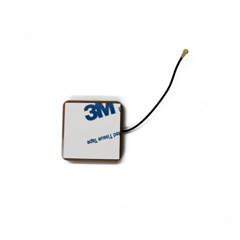
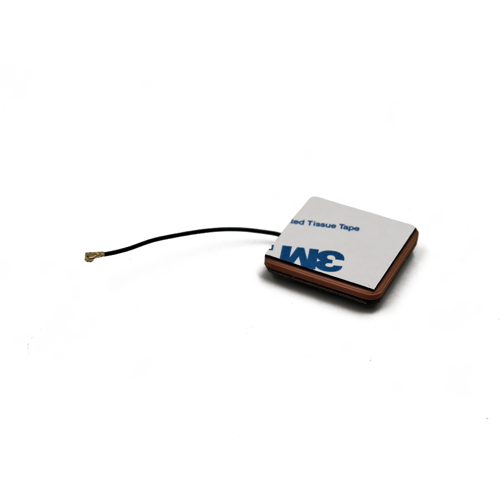
Ceramic Antenna: This defines the core radiating element itself. The antenna is fabricated from a specialized ceramic material, typically a formulation based on barium strontium titanate or similar, which has a very high dielectric constant (εr). A high dielectric constant allows the electromagnetic waves to wavelength-shorten within the material. This property is the key to miniaturization; it enables the design of a patch antenna that resonates at the target GNSS frequencies (around 1.5 GHz) while maintaining a physically small footprint, often as small as 10mm x 10mm x 4mm. The ceramic patch is metallized on its top and bottom surfaces, creating a resonant cavity.
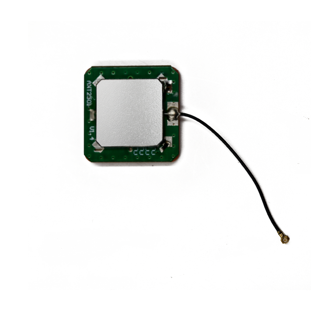
A typical system comprises three main components:
The Ceramic Radiator: The patch antenna that resonates at GNSS frequencies and converts electromagnetic waves into electrical currents.
The Low-Noise Amplifier (LNA): A semiconductor amplifier circuit that provides gain (e.g., 15-28 dB) with a very low noise figure (e.g., 0.5-1.5 dB).
The Band-Pass Filter: Often integrated with the LNA, this filter is essential for rejecting powerful out-of-band interference from cellular (4G/5G), Wi-Fi, Bluetooth, and other RF transmitters that are invariably present in modern devices. Without this filtering, these signals can desensitize or overload the sensitive GNSS receiver.
The evolution towards embedded active ceramic antennas has been driven by an insatiable market demand for smaller, cheaper, more reliable, and better-performing location-enabled devices. They represent a perfect marriage of materials science, electromagnetic theory, and semiconductor electronics, packaged into a tiny, robust form factor that has enabled the proliferation of GNSS technology into nearly every facet of our lives. Their ability to provide robust performance despite the constraints of integration is a testament to advanced engineering and makes them the unsung hero of the positioning revolution.
The design and construction of an embedded active GNSS ceramic antenna system is a complex, multi-disciplinary process that balances electromagnetic performance, mechanical constraints, thermal management, and economic feasibility. It is an intricate dance between theory and practical implementation, where every design decision has a profound impact on the final performance of the system. This section explores the materials, architectural choices, and integration considerations that define these sophisticated components.
The Ceramic Patch Antenna Core:
The foundation of the system is the ceramic patch antenna. Its design begins with the selection of the ceramic material. Engineers choose materials with a high dielectric constant (εr), typically ranging from 20 to over 90. A higher εr allows for a smaller physical size for the same resonant frequency, as the wavelength within the dielectric is reduced by a factor of √εr. However, this advantage comes with trade-offs. Very high dielectric constants can lead to:
Bandwidth Reduction: The operational bandwidth of the antenna becomes narrower, which is problematic for receiving multiple GNSS bands that require a broad bandwidth.
Increased Loss Tangent: Materials with very high εr often have higher loss tangents (tan δ), which translates to lower radiation efficiency as more energy is dissipated as heat within the ceramic itself.
Fabrication Tolerances: The higher the εr, the more sensitive the antenna's performance is to minor variations in manufacturing dimensions and material properties.
Therefore, material selection is a critical compromise between size, bandwidth, and efficiency. The ceramic is precision-ground into a specific geometry, usually a flat, rectangular or square block. Its bottom surface is fully metallized to form the ground plane, while the top surface has a specific metallized pattern that defines the radiating element. The feed point—where the RF energy is transferred to the amplifier—is crucial. It can be probe-fed (a pin connecting through the ceramic), aperture-coupled (fed by a microstrip line underneath the ground plane through a slot), or edge-fed. Each method has implications for impedance matching, bandwidth, and isolation.
The Low-Noise Amplifier (LNA) and Filtering:
The active component is the LNA, which is almost always based on a Gallium Arsenide (GaAs) or advanced Silicon Germanium (SiGe) pseudomorphic high-electron-mobility transistor (pHEMT) process. These semiconductor technologies are chosen for their exceptional ability to provide high gain with remarkably low inherent noise. The LNA is designed for a specific gain, often between 15 dB and 28 dB. Too little gain and the signal remains too weak; too much gain and the amplifier can be easily overloaded by strong nearby interferers, causing compression and desensitization.
Equally important is the integration of a band-pass filter. This is typically a Surface Acoustic Wave (SAW) or Bulk Acoustic Wave (BAW) filter placed either before the LNA (to prevent strong interferers from overloading it) or after it. The filter is sharply tuned to the GNSS bands (e.g., 1559-1610 MHz) and provides high rejection (e.g., 30-40 dB) to signals outside this passband, particularly from cellular bands (700 MHz to 3.5 GHz). The entire amplifier and filter circuit is designed on a small PCB, often using a high-frequency laminate like Rogers RO4003, and is packaged into a shielded metal can to prevent external noise coupling and to act as an electromagnetic interference (EMI) shield.
Integration and System-Level Considerations:
The true challenge lies in integrating the ceramic radiator, the active module, and the device's main PCB into a cohesive system. The performance is heavily influenced by the surrounding environment:
Ground Plane: The size and shape of the host PCB's ground plane are critical. The ceramic patch antenna couples energy to the ground plane, which acts as part of the radiating structure. A larger ground plane typically supports better efficiency and a more symmetric radiation pattern. A small or irregular ground plane can detune the antenna and create nulls in its pattern.
Placement: Antenna placement is paramount. It must be located away from noisy digital components (processors, memory, switching regulators) and other RF transmitters (cellular, Wi-Fi antennas) to avoid interference and blocking. The rule of thumb is maximum possible isolation, both physically and through frequency separation.
Desense and Mitigation: "Desensitization" (desense) occurs when a powerful transmitter drowns out the weak GNSS signal. Careful layout, the use of shielding cans over noisy components, and strategic placement of the GNSS antenna are essential countermeasures. The device casing also plays a role; metal casings can shield the antenna, requiring careful design like plastic injection windows or laser-direct-structuring (LDS) of antenna patterns onto the housing itself.
Finally, the entire system must be tested and tuned within the final product enclosure. This involves measuring key parameters like return loss (S11), gain, efficiency, noise figure, and system-level sensitivity (e.g., Time-To-First-Fix (TTFF) and tracking sensitivity). Iterative adjustments to the matching network between the antenna and the LNA are almost always required to achieve optimal performance in the real-world application. The construction is thus a holistic process, transforming a theoretical design into a practical, high-performing, and reliable embedded subsystem.
Understanding the working principles of an embedded active GNSS ceramic antenna system requires a journey from the vacuum of space to the silicon of a microprocessor. It is a process of capturing incredibly faint whispers of radio energy, carefully amplifying them, and delivering a clean, strong signal to a receiver that can decode it into a precise position and time. This section breaks down this process into its fundamental stages: radiation, amplification, filtering, and transmission.
Stage 1: Signal Capture and Radiation (The Ceramic Patch)
The process begins when right-hand circularly polarized (RHCP) electromagnetic waves, transmitted by GNSS satellites orbiting over 20,000 km away, impinge upon the ceramic patch antenna. The choice of RHCP is intentional, as it is less susceptible to signal degradation caused by Faraday rotation in the ionosphere and reflections from buildings and terrain than linearly polarized waves.
The ceramic patch is a resonant cavity. Its physical dimensions (length and width) are meticulously calculated to be slightly less than half the wavelength of the target GNSS frequency within the high-dielectric ceramic material. When the RF wave hits the patch, it induces oscillating currents on its metallized surface. If the frequency of the incoming wave matches the resonant frequency of the patch, these currents are reinforced, creating a standing wave pattern. This resonance allows the antenna to efficiently convert the electromagnetic energy from the satellite into a fluctuating voltage at its feed point. The antenna's performance is characterized by its bandwidth (the range of frequencies it can receive efficiently), its radiation pattern (a 3D representation of its sensitivity in different directions), and its gain (a measure of its directionality and efficiency).
Stage 2: Initial Low-Noise Amplification
The voltage signal generated at the antenna's feed point is extraordinarily weak, typically around -130 dBm (0.1 femtowatts). This is well below the thermal noise floor and the sensitivity of any practical receiver. Furthermore, any cable used to connect the antenna to the receiver would introduce signal loss (attenuation), making the signal even weaker and raising the overall system noise figure.
This is where the "active" component becomes critical. The weak signal is immediately routed to the Low-Noise Amplifier (LNA), which is located mere millimeters away. The primary function of the LNA is to provide significant voltage gain (e.g., 20 dB would amplify a -130 dBm signal to -110 dBm) while adding the absolute minimum amount of its own electronic noise. This is quantified by its Noise Figure (NF), which represents the degradation in the Signal-to-Noise Ratio (SNR) caused by the amplifier itself. A perfect amplifier would have an NF of 0 dB. In practice, state-of-the-art LNAs for GNSS achieve NFs between 0.5 dB and 1.0 dB. This first stage of amplification is the most important in the entire signal chain for preserving SNR, as dictated by Friis's formula for noise.
Stage 3: Band-Pass Filtering for Interference Rejection
The amplified signal now contains not just the desired GNSS signals but also a plethora of unwanted RF energy from other services. In a modern device, the GNSS antenna often resides next to powerful transmitters for cellular, Wi-Fi, and Bluetooth. A 4G/5G cellular transmission can be +23 dBm (200 milliwatts) or more, which is over 150 dB stronger than the GNSS signal. Without protection, these signals would easily overload the subsequent stages of the GNSS receiver, rendering it useless.
To prevent this, a band-pass filter is integrated into the active module. This filter, often a SAW filter, is designed to have very low insertion loss within the GNSS band (e.g., 1559-1610 MHz) but very high rejection outside of it. It acts as a gatekeeper, allowing the amplified GNSS signals to pass through while dramatically attenuating any out-of-band interference from cellular, Wi-Fi, and other sources. This filtering is essential for ensuring the receiver operates linearly and can process the desired weak signals without being "blinded" by stronger, irrelevant ones.
Stage 4: Signal Delivery to the Receiver
The now-amplified and filtered signal is output from the active antenna module. It typically requires a DC bias voltage (e.g., 3.3V) to power the LNA, which is often supplied from the GNSS receiver chip itself through the same coaxial cable used for the RF signal, using a bias tee circuit. The signal travels to the GNSS receiver IC on the device's main board.
The receiver then performs the complex tasks of down-converting the RF signal to a lower intermediate frequency (IF), digitizing it with an Analog-to-Digital Converter (ADC), and using sophisticated digital signal processing (DSP) algorithms to acquire and track the codes from multiple satellites, ultimately calculating the device's position, velocity, and time (PVT). The role of the embedded active ceramic antenna system is complete: it has successfully captured a whisper from space, given it a powerful voice, and delivered it clearly to the decoder, enabling the miracle of modern navigation.
The widespread adoption of embedded active GNSS ceramic antenna systems is a direct result of their compelling advantages over alternative solutions like external passive antennas or PCB trace antennas. However, their integration is not without significant challenges. A clear understanding of both sides of this equation is essential for product designers and engineers.
Advantages:
Superior Miniaturization and Integration: This is the foremost advantage. The high dielectric constant of the ceramic material allows the antenna to be manufactured in very small form factors (e.g., 10x10x4 mm), making it ideal for space-constrained consumer electronics like smartphones, smartwatches, and trackers. Its embedded nature means it does not require external protrusions, preserving the sleek design of modern devices.
Enhanced Sensitivity and Performance: The integrated LNA provides crucial gain at the very point of signal capture, overcoming the losses of any subsequent cabling and PCB traces. This results in a significantly higher overall signal-to-noise ratio (SNR) delivered to the receiver compared to a passive antenna. This translates directly into better performance: faster Time-To-First-Fix (TTFF), the ability to acquire and track signals in weaker environments (e.g., under tree cover, in urban canyons), and generally higher accuracy.
Improved Noise Immunity: By amplifying the signal before it encounters the lossy and potentially noisy environment of the main PCB, the active design mitigates the degradation of SNR. The integrated band-pass filter provides robust rejection of out-of-band interference, which is critical for operation in the spectrally crowded environment of a multi-radio device.
Design Flexibility and Reliability: Ceramic antennas can be placed on a PCB in various locations, offering designers some flexibility to work around other components. Furthermore, as a single, packaged surface-mount device (SMD), they are highly reliable and suitable for automated pick-and-place assembly, reducing manufacturing costs and improving consistency compared to manually assembled external antennas. They are also mechanically robust, with no moving parts or cables that can break.
Multi-Band/Multi-Constellation Support: Advanced ceramic antenna designs can support multiple resonant modes, allowing a single component to receive signals from L1, L2, L5, and other GNSS bands. This enables the use of multi-constellation, multi-frequency receivers that offer significantly improved accuracy, integrity, and reliability through advanced techniques like dual-frequency ionospheric correction.
Challenges and Limitations:
Performance Dependency on Host Environment: This is the single greatest challenge. The performance of an embedded ceramic antenna is inextricably linked to the device into which it is integrated. The size and shape of the PCB's ground plane are critical; a small or irregular ground plane can severely detune the antenna and distort its radiation pattern. The proximity of other components, batteries, and the device's housing (especially metal casings) can all dramatically impact efficiency and bandwidth.
Susceptibility to Internal Interference (Desense): While the filter rejects out-of-band interference, the antenna is still vulnerable to noise generated within the device itself. High-speed digital circuits (processors, memory buses) and switching power regulators can generate broad-spectrum noise that falls within the GNSS passband. Similarly, harmonic emissions from other RF transmitters (cellular, Wi-Fi) can leak into the GNSS band. Careful board layout, shielding, and filtering of noise sources are mandatory and add design complexity.
Limited Bandwidth and Thermal Drift: The high dielectric constant that enables miniaturization also inherently limits bandwidth. Designing a single ceramic patch that covers all GNSS bands (from ~1176 MHz for L5 to ~1602 MHz for BeiDou B1) with high efficiency is a major engineering challenge. Furthermore, the dielectric constant of ceramic materials is temperature-sensitive. As the device heats up during operation (e.g., from the processor or cellular modem), the material properties change, causing the antenna's resonant frequency to "drift," which can degrade performance if not properly accounted for in the design.
Cost and Design Complexity: While unit costs have decreased, an active ceramic antenna system is still more expensive than a simple passive PCB trace antenna. It requires additional components (LNA, filter, bias tee, matching networks) and more complex PCB real estate. Furthermore, the design process is non-trivial, requiring significant RF expertise, electromagnetic simulation software, and extensive prototyping and testing in the final product enclosure to validate performance. This raises the barrier to entry and the development cost.
Fixed Radiation Pattern: Unlike an external antenna that can be oriented for optimal sky view, an embedded antenna's orientation is fixed by the device's usage. A phone in a user's pocket or a tracker in a truck's metallic cabin may have its antenna severely obstructed. While diversity techniques using multiple antennas are emerging, this remains a fundamental limitation of the embedded approach.
In conclusion, the advantages of small size, high performance, and integrability make embedded active ceramic antennas the best choice for most mass-market applications. However, successfully overcoming the challenges of environmental dependency and interference requires a systems-level approach and deep RF design expertise.
The applications for embedded active GNSS ceramic antenna systems are vast and continually expanding, driven by the global demand for location intelligence. Their unique blend of small size, robust performance, and reliability has made them the enabling technology for a myriad of devices across diverse industries. Concurrently, ongoing research and development are pushing the boundaries of their capabilities, shaping exciting future trends.
Current Applications:
Consumer Electronics: This is the highest-volume market.
Smartphones and Tablets: Essential for navigation, location-based services, geotagging, and emergency location (e.g., E911).
Wearables: Smartwatches and fitness trackers use GNSS for tracking runs, cycles, and hikes without requiring a paired phone.
Cameras and Drones: Drones rely on GNSS for stabilization, autonomous flight, and return-to-home functions. Action cameras use it for geotagging photos and videos.
Personal Trackers: Used for tracking children, pets, and valuable assets.
Automotive and Telematics:
In-Vehicle Infotainment (IVI) and Navigation Systems: Providing turn-by-turn navigation and traffic information.
Telematics Control Units (TCUs): Black boxes for usage-based insurance, fleet management, stolen vehicle recovery, and predictive maintenance. They track vehicle location, speed, and driving behavior.
Advanced Driver-Assistance Systems (ADAS) and Autonomous Vehicles: GNSS is a critical sensor for ADAS features like adaptive cruise control and for providing absolute position and time to autonomous driving systems, often fused with inertial sensors and camera data.
Internet of Things (IoT) and Machine-to-Machine (M2M):
Asset Tracking: Monitoring the location of shipping containers, pallets, and high-value goods across global supply chains.
Agricultural Technology (AgriTech): Precision farming equipment uses GNSS for guided steering, variable rate application of seeds/fertilizers, and field mapping.
Smart City Infrastructure: Timing synchronization for networks, monitoring of infrastructure, and smart utility meters.
Micro-Mobility: E-scooters and e-bikes use GNSS for tracking location for rental services, implementing geofencing, and preventing theft.
Future Trends:
Multi-Band and Multi-Constellation Becomes Standard: The future is unquestionably multi-frequency (L1 + L5/E5a) and multi-constellation (GPS, Galileo, GLONASS, BeiDou). This trend is driven by the demand for centimeter-level accuracy using Real-Time Kinematic (RTK) and Precise Point Positioning (PPP) techniques, which require dual-frequency measurements to correct for ionospheric delay. Ceramic antennas are evolving to support these wider bandwidths efficiently.
Antenna Diversity and Advanced Receivers: To combat signal blockage in challenging environments, systems will increasingly use two or more antennas (diversity). This allows the receiver to select the antenna with the strongest signal or even combine signals to improve robustness. More advanced systems may use phased arrays to enable directional "beamforming," actively steering the antenna's gain pattern towards visible satellites.
Tighter Integration with Other RF Systems (AiP): Antenna-in-Package (AiP) technology is a growing trend where the antenna is integrated directly into the package of the GNSS receiver chip or a larger RF module that includes cellular and Wi-Fi. This further reduces size, simplifies design for OEMs, and can improve performance by minimizing transmission line losses. This represents the next step in miniaturization and integration beyond the current embedded-on-PCB approach.
Enhanced Interference Mitigation and Resilience: As the RF environment becomes more congested, both from legitimate sources and from malicious jamming/spoofing, future active antennas will incorporate more sophisticated on-board interference detection and mitigation techniques. This could involve adaptive filtering or even collaborative filtering with other radios in the device.
Focus on Low-Power Operation for IoT: For battery-powered IoT devices that need to last for years on a single charge, power consumption is paramount. Future LNAs and active antenna systems will be optimized for ultra-low power consumption, potentially incorporating duty-cycling features where the amplifier is only powered when a signal is expected to be processed.
Materials and Simulation Advancements: Research into new ceramic and substrate materials with more stable temperature properties and even higher dielectric constants will continue to push the limits of miniaturization and performance. Furthermore, advancements in 3D electromagnetic simulation software will allow designers to more accurately predict antenna performance within the complete device environment before physical prototyping, reducing development time and cost.
The trajectory is clear: embedded active GNSS ceramic antenna systems will become even more performant, more integrated, more intelligent, and more essential. They will be a foundational technology enabling the next generation of autonomous systems, ubiquitous IoT, and high-precision applications that we are only beginning to imagine.
Conclusion
The embedded active GNSS ceramic antenna system is a masterpiece of modern engineering, a testament to the incredible innovation that occurs when the fields of materials science, electromagnetics, and semiconductor technology converge. It is a technology that often goes unnoticed, hidden within the sleek enclosures of our everyday devices, yet it performs the Herculean task of bridging the vast gulf between Earth and space. By capturing faint whispers from satellites orbiting over 20,000 kilometers away and amplifying them into a clear signal, this subsystem serves as the critical gateway for the positioning, navigation, and timing data that underpins our modern world.
As we have explored, its development is a complex balancing act. The choice of ceramic material dictates a trade-off between the paramount need for miniaturization and the essential requirements of bandwidth and efficiency. The integration of a low-noise amplifier and sophisticated filtering is what transforms a simple radiator into a high-performance system, capable of operating in the spectrally hostile environment of a multi-radio device. However, this integration comes with its own set of challenges, primarily its profound dependence on the host device's design—the size of its ground plane, the placement of noisy components, and the material of its casing all play a decisive role in ultimate performance.
Despite these challenges, its advantages are overwhelming for a vast range of applications. The ability to provide robust, high-sensitivity GNSS reception in an incredibly small, reliable, and cost-effective surface-mount package has been the key enabler for the proliferation of location awareness. From the smartphone in your hand and the wearable on your wrist to the telematics unit in your car and the tracker on a shipping container, this technology is silently at work, providing the invaluable data of "where" and "when."
Looking forward, the evolution of this technology is aligned with the demands for higher precision, greater reliability, and deeper integration. The shift towards multi-band, multi-constellation support, the exploration of antenna diversity and AiP, and the continuous battle against interference and jamming are not mere incremental improvements but necessary steps to support future autonomous systems and the ever-expanding IoT universe.
In conclusion, the embedded active GNSS ceramic antenna is far more than a simple component. It is a sophisticated, essential, and enabling subsystem. It has moved from being a specialty RF item to a commoditized yet highly advanced piece of technology that is fundamental to the功能 (function) and form of contemporary electronic devices. Its continued development will remain at the forefront of the effort to make our world more connected, efficient, and intelligent, one precise location at a time.

 86 0755 2819 9597
Lucy Yang | lucy.y@toxutech.com
Nicole Li | nicole@toxutech.com
Dotty Zhao | sales04@toxutech.com
Global Business Director / Sales Team / Global Operations


 En
En Cn
Cn Korean
 Home >


