

-
Products -PCBA Manufacturing RF Connectors RF Cable Assemblys Embedded Antennas External Antennas Positioning Chips and Modules
RF Connectors

RF Cable Assemblys
Embedded Antennas
External Antennas
Positioning Chips and Modules


 Language


Language


In an increasingly interconnected world, the demand for real-time, global tracking and monitoring of assets, vehicles, and even wildlife has exploded. From shipping containers crossing oceans to scientific sensors in the Arctic, the need to transmit data from anywhere on Earth is paramount. While Global Navigation Satellite Systems (GNSS) like GPS excel at determining location, they are primarily one-way receive-only systems. Transmitting that location data, or any other sensor information, from remote areas requires a different kind of connectivity. This is where the Iridium satellite constellation and its specialized antennas come into play, forming the critical return-link communication lifeline.
Iridium Communications Inc. operates a unique network of 66 cross-linked low-earth orbit (LEO) satellites, plus spares, that provide truly global coverage, including poles, oceans, and airspace. Unlike geostationary satellites, which hover over a fixed point 36,000 km above the equator, Iridium's LEO satellites orbit at approximately 780 km, resulting in lower latency and making communication feasible with small, low-power devices. The Iridium network is designed for robust, narrowband data and voice communication, making it the gold standard for Mission-Critical IoT (MC-IoT) and personal safety applications.
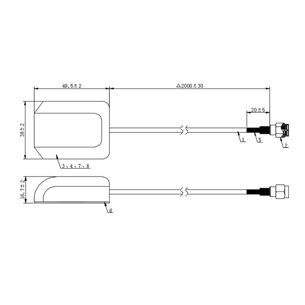
At the heart of any Iridium tracking device is its antenna. This component is not a passive receiver but an active transceiver, responsible for both receiving signals from the satellites and, more critically, transmitting data packets up to them. A compact external Iridium antenna is engineered to be a self-contained, weatherproof unit that can be mounted on the exterior of an asset—a ship's mast, a truck's roof, a container's side, or a backpack—to ensure a clear, unobstructed view of the sky for optimal satellite connectivity.
The challenge these antennas overcome is immense. They must operate in the L-band spectrum, specifically around 1616-1626.5 MHz for downlink (satellite to device) and 1616-1626.5 MHz for uplink (device to satellite). Transmitting a signal from a small, battery-powered device to a satellite moving at over 27,000 km/h requires an antenna with efficient gain and precise characteristics. Furthermore, the antenna must be extraordinarily resilient, capable of operating across a brutal temperature range (-40°C to +85°C is standard), resisting corrosion from salt spray, enduring prolonged UV exposure, and remaining fully waterproof against driving rain and waves.
The applications are as diverse as they are critical:
Maritime: For vessel tracking, emergency SOS (GMDSS), and data reporting from buoys and scientific equipment.
Aviation: For flight tracking, cockpit data transmission (ACARS), and emergency locator beacons (ELTs).
Land Transportation: For tracking heavy machinery, trucks, and rail cars in areas with no cellular coverage.
Personal Safety: For personal locator beacons (PLBs) and messaging devices for adventurers, pilots, and sailors.
Industrial IoT: For remote monitoring of pipelines, wellheads, and electrical substations in extreme environments.
Environmental Science: For transmitting data from remote weather stations, animal tracking collars, and seismic sensors.
In essence, the compact external Iridium antenna is the vital enabler of global bidirectional communication. It is the unsung hero that transforms a local tracking device into a global asset, ensuring that no matter how remote the location, the data—and a call for help—can always get through.
The design of a compact external Iridium antenna is a complex exercise in balancing electromagnetic performance, extreme environmental durability, and minimal physical footprint. Every aspect of its construction is meticulously chosen to meet the harsh demands of its operating environment while fulfilling the strict electrical requirements of the Iridium network.
1. Radiating Element and Antenna Type:
The core of the antenna is its radiating element. For compact external Iridium antennas, the most common types are variants of the quadrifilar helix antenna (QHA) or planar inverted-F antenna (PIFA) designs, often integrated into a ceramic patch or a helical structure within a radome.
Quadrifilar Helix Antenna (QHA): This is a highly popular design for satellite communication. It consists of four helical elements fed in phase quadrature (90 degrees apart). This design creates a naturally hemispherical radiation pattern, which is ideal for communicating with satellites that can appear anywhere in the sky, from horizon to horizon. It provides excellent gain at low elevation angles, which is crucial for catching satellites as they rise and set. Modern manufacturing techniques allow these intricate elements to be precision-etched onto a cylindrical substrate, making them compact and robust.
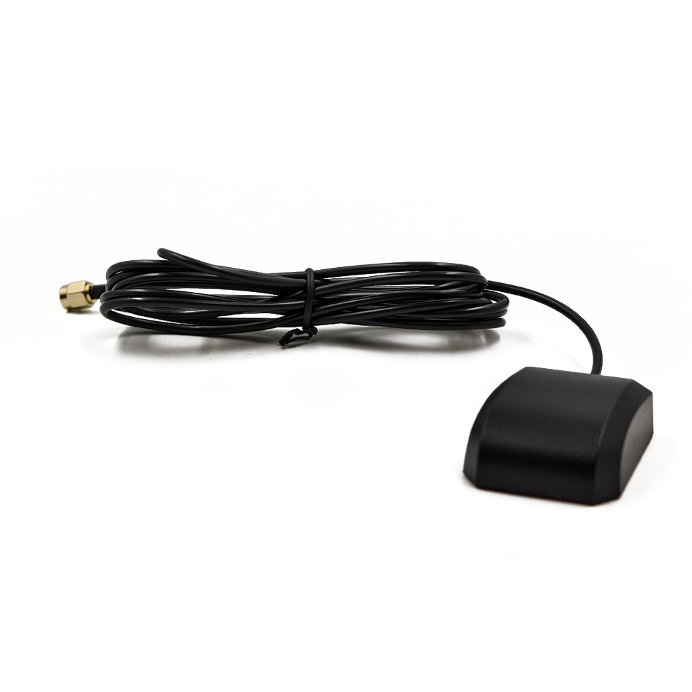
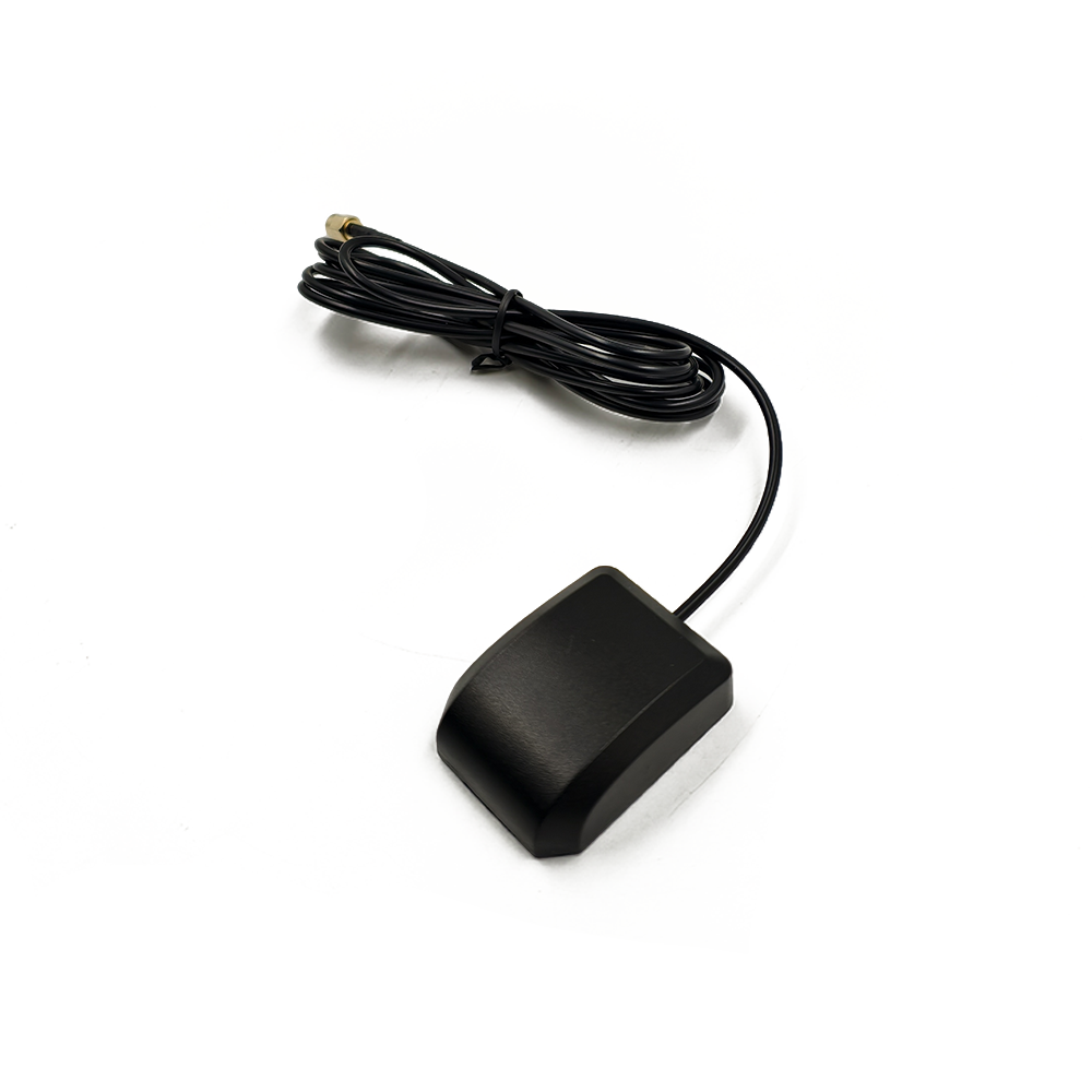
Patch Antenna (PIFA): Often seen in a low-profile, puck-style form factor. These are printed circuit board (PCB) based antennas where the radiating element is a carefully shaped copper trace on a dielectric substrate. They are valued for their very low vertical profile and mechanical robustness. Sophisticated multilayer designs are used to achieve the required bandwidth and hemispherical coverage. Their flat "puck" shape makes them aerodynamically efficient and easy to mount on flat surfaces.
2. The Radome: The Protective Shell:
The radiating elements are encased in a protective shell called a radome. This is far more than just a cover; it is a critical part of the antenna system.
Material: The radome is typically injection-molded from high-grade engineering plastics. Polyetherimide (PEI), such as Ultem, is a common choice due to its exceptional dielectric properties, high mechanical strength, and incredible resistance to UV radiation and a wide range of chemicals. Other materials include Polyphenylene Sulfide (PPS) and glass-filled thermoplastics.
Function: The radome must be transparent to RF energy at 1.6 GHz. Its shape, thickness, and material properties are engineered to have minimal impact on the antenna's radiation pattern. It also provides crucial environmental protection, forming a hermetic seal to keep moisture and dust out. The color is almost always high-gloss white or black, specifically formulated to reflect UV light and prevent solar heating and material degradation.
3. Ground Plane Integration:
Antenna performance is heavily dependent on its ground plane—a conductive surface that acts as a reflector for the radiating element. For a compact external antenna, this is a major design challenge. Some designs are ground-plane dependent, meaning they must be mounted on a large metal surface (e.g., a vehicle roof) to function correctly. The vehicle's body itself becomes the ground plane. Other advanced designs are ground-plane independent, incorporating their own integrated ground plane or counterpoise within the radome. This makes them far more versatile, allowing for effective installation on non-metallic surfaces like fiberglass boat decks or plastic containers, though often at the cost of slightly reduced peak performance or a larger size.
4. Internal Construction and Feed Network:
Inside the radome, a complex assembly exists:
Feed Network: For a QHA, a small PCB contains the phasing network that ensures the four elements are driven with the correct phase relationship. This is a delicate and precise circuit.
Matching Circuitry: Miniature capacitors and inductors are used to "tune" the antenna, ensuring a good impedance match (typically 50 ohms) to the coaxial cable across the entire Iridium bandwidth. This minimizes the Voltage Standing Wave Ratio (VSWR) and maximizes power transfer.
Connectorization: The antenna is terminated with a ruggedized coaxial connector, most commonly a TNC or SMA type. Crucially, the interface is made waterproof, often using an integrated O-ring and a threaded coupling nut that compresses the seal against the mounting surface.
5. Sealing and Environmental Protection:
Achieving a waterproof rating of IP67 or IP69K is non-negotiable. This is accomplished through:
Ultrasonic Welding or Epoxy Sealing: The two halves of the radome are fused together using ultrasonic welding, creating a permanent, molecular bond that is impervious to moisture. High-performance epoxy is also used to seal cable entry points and connectors.
Silicone Gaskets and O-rings: Where serviceable connections are needed, such as at the coaxial connector interface, compression seals made of silicone (which remains flexible across the entire temperature range) are used.
The construction of these antennas is a testament to advanced materials science and precision RF engineering, resulting in a device that is both an exceptional electronic component and a formidable piece of environmental hardware.
The operation of a compact Iridium antenna is a fascinating application of electromagnetic theory, designed to solve the unique problem of communicating between a fixed point on Earth and a fast-moving satellite in LEO.
1. Establishing a Link: The Isotropic Reference and Gain:
The fundamental challenge is energy. The tracking device has a limited power budget, often running on batteries. The transmitter power amplifier might only output 1-2 watts of RF power. This signal must travel over 700 km through the atmosphere to a satellite.
An isotropic radiator is a theoretical point source that radiates power equally in all directions. Its performance is the baseline (0 dBi gain). A practical antenna must focus this limited energy in useful directions rather than wasting it, for example, into the ground or straight up. The hemispherical pattern of a QHA or a well-designed patch antenna does exactly this. It concentrates radiated energy toward the horizon and across the entire upper hemisphere. This concentration is measured as gain, expressed in dBi (decibels relative to an isotropic radiator). A typical compact Iridium antenna might have a peak gain of 2-4 dBi at low elevation angles. This doesn't amplify the power; it redirects it, making the transmitted signal effectively stronger in the directions where satellites are most likely to be.
2. The Radiation Pattern: A Hemisphere of Coverage:
The antenna's radiation pattern is its most important property. It is a 3D representation of its effectiveness in different directions. For Iridium, a near-ideal pattern is a wide, smooth hemisphere. The goal is to have strong performance from the horizon (0 degrees elevation) up to the zenith (90 degrees). This ensures that whenever a satellite comes into view—even one just barely above the horizon—the antenna can establish and maintain a strong link. The pattern must be as omnidirectional as possible in the azimuth (compass) plane, meaning it performs equally well regardless of which direction the device is facing. This is critical for assets that move and rotate, like ships or vehicles.
3. Polarization: Matching the Satellite:
Polarization refers to the orientation of the electromagnetic wave's electric field. Iridium satellites use right-hand circular polarization (RHCP). To maximize power transfer, the antenna on the tracking device must also be RHCP. A wave transmitted with RHCP and received with an RHCP antenna will experience minimal polarization mismatch loss. A QHA inherently produces RHCP, making it a perfect match for the system. This is a key advantage over simpler linear polarized antennas, which would suffer significant and variable loss as the satellite moves across the sky.
4. The Complete Communication Cycle:
Transmission (Uplink): The tracking device's modem generates a data packet. The power amplifier boosts this signal to a few watts. The coaxial cable delivers this RF energy to the antenna. The antenna's radiating elements transform the electrical current into an electromagnetic wave, shaped by its pattern and focused by its gain, and launch it into space with RHCP.
Reception (Downlink): The process works in reverse. A weak signal from a satellite arrives at the antenna. The wave induces tiny electrical currents in the radiating elements. These signals are passed through the matching network to the coaxial cable and onward to the device's receiver, which is highly sensitive to decode the faint transmission.
5. Impact of the Environment:
The antenna's performance is constantly tested by its environment. Rain can attenuate L-band signals. Metal structures nearby can distort the radiation pattern. The antenna's design—its rugged radome, integrated seals, and corrosion-resistant materials—ensures that its electrical characteristics remain stable through these challenges, providing a reliable and predictable RF interface day after night, in all conditions.
The use of a compact Iridium antenna brings a unique set of powerful advantages alongside non-trivial challenges that designers must carefully manage.
Advantages:
True Global Coverage: The single, overwhelming advantage. It works anywhere on the planet, providing connectivity in regions completely devoid of cellular or terrestrial networks.
Reliability and Resilience: The Iridium network is designed for mission-critical communications. The LEO constellation has multiple satellites in view at any time, providing redundancy. The antennas themselves are built to military-grade environmental standards, ensuring operation in the most extreme conditions.
Low Latency: Due to the low orbital altitude, signal latency is significantly lower (20-50ms) compared to geostationary satellites (500-600ms), making it suitable for near-real-time two-way messaging and commands.
Compact Form Factor: Modern designs allow for highly effective antennas in very small packages (e.g., puck antennas as small as 25mm tall and 60mm in diameter), enabling their use on a vast array of assets without being obtrusive.
Standardized Integration: The use of standard coaxial interfaces (TNC, SMA) simplifies the integration process for device manufacturers, who can source antennas from multiple specialized vendors.
Challenges:
Power Consumption: Transmitting to a satellite is power-intensive. A successful transmission burst may require the device to draw several amps for a few seconds. This places a heavy burden on the device's battery, making power management the central design challenge for any battery-operated tracker.
Data Throughput and Cost: Iridium is a narrowband system. The legacy Short Burst Data (SBD) service is limited to ~340 bytes per message. While the new Certus® 100 service offers higher rates, it is fundamentally for small data packets. This makes it ideal for telemetry and GPS coordinates but unsuitable for large data transfers. Furthermore, airtime data costs are significantly higher than cellular services.
Link Margin and Obstructions: Achieving a reliable link requires sufficient "link margin" – a buffer of extra signal strength to overcome obstacles. The antenna must have a clear view of the sky. Placement under decks, inside metal containers, or in dense urban canyons can block signals and prevent communication.
Complexity of Design: Designing a high-performance, ground-plane independent antenna that is also small and robust is extremely challenging from an RF perspective. This R&D investment is reflected in the unit cost of the antenna itself, which is higher than a simple cellular or GNSS antenna.
Regulatory Certification: Any device using the Iridium network must undergo rigorous certification processes (Iridium's own PLUS certification, as well as FCC, CE, etc.). The antenna is a critical part of this, and any change requires re-testing, adding time and cost to development.
The applications for these antennas are vast and growing as the cost of satellite connectivity decreases and the IoT ecosystem expands.
Applications:
Maritime Domain: The quintessential application. Used for:
Vessel Tracking: Global AIS tracking for commercial fishing, shipping, and yachts.
Emergency Communications: Integral part of GMDSS-approved EPIRBs and SSAS systems.
Oceanographic Data Buoys: Transmitting environmental data from remote buoys.
Land-Based Asset Tracking: Monitoring high-value cargo, railcars, and heavy equipment in remote mining, construction, and agricultural sites far beyond the cellular grid.
Aviation: Flight tracking and data transmission (ACARS) for aircraft flying over oceans and remote regions (e.g., polar routes). Emergency Locator Transmitters (ELTs).
Personal Safety and Adventure: SPOT, Garmin inReach, and other personal locator beacons (PLBs) that allow hikers, sailors, and pilots to send SOS and text messages.
Government and Defense: Secure tracking of military assets, border patrol operations, and communication for special forces in denied environments.
Environmental and Scientific Research: Wildlife tracking collars on migratory species, data backhaul from remote weather stations, and seismic monitoring.
Future Trends:
Iridium Certus® and Higher Data Rates: The new Iridium Certus platform is a game-changer. While Certus 100 is perfect for tracking, it paves the way for smaller antennas to support even higher data rates (e.g., Certus 200/350), enabling more complex IoT applications like remote control and firmware-over-the-air (FOTA) updates.
Antenna and Modem Integration: The trend is towards highly integrated "antenna modules" that combine the RF element, the Iridium modem, and the GNSS receiver into a single, sealed unit. This simplifies design for OEMs, reducing time-to-market.
Active Antenna Systems: Incorporating Low-Noise Amplifiers (LNAs) and Power Amplifiers (PAs) directly within the antenna radome to improve overall system link margin and compensate for cable losses.
Multi-Constellation/Multi-Function Antennas: Development of single antennas that can operate on Iridium, GNSS (GPS, Galileo), and even other LEO constellations (e.g., Starlink for IoT), reducing the number of antennas needed on a platform.
Enhanced Durability and Sustainability: Continued innovation in materials to create even more robust radomes and more environmentally friendly manufacturing processes, alongside designs that can operate in expanding temperature ranges.
Conclusion
The compact external Iridium antenna is a masterpiece of focused engineering. It is a device that embodies a single, critical purpose: to provide a reliable, resilient, and globally available communication link for data and SOS signals where no other option exists. It is the key technological bridge that connects the isolated, the mobile, and the critical to the rest of the world.
Its significance cannot be overstated. It is not merely a component; it is an enabler of safety, efficiency, and knowledge. It is the reason a sailor in distress in the South Pacific can summon help, a scientist can understand climate change through data from the Antarctic, and a logistics company can optimize its global supply chain. It transforms a local device into a node on a planetary network.
As technology evolves, the demand for global connectivity will only grow. The advent of new LEO constellations and advanced services like Iridium Certus will not make this antenna obsolete but will instead demand even more sophisticated, efficient, and integrated versions of it. The compact external Iridium antenna will remain a fundamental, indispensable pillar of global satellite communication, ensuring that no matter how remote the asset or how important the message, the connection will always be made.

 86 0755 2819 9597
Lucy Yang | lucy.y@toxutech.com
Nicole Li | nicole@toxutech.com
Dotty Zhao | sales04@toxutech.com
Global Business Director / Sales Team / Global Operations


 En
En Cn
Cn Korean
 Home >


