

-
Products -PCBA Manufacturing RF Connectors RF Cable Assemblys Embedded Antennas External Antennas Positioning Chips and Modules
RF Connectors

RF Cable Assemblys
Embedded Antennas
External Antennas
Positioning Chips and Modules


 Language


Language


In the invisible tapestry of wireless communication that connects our modern world, the antenna serves as the fundamental transducer, bridging the gap between guided electromagnetic waves in a circuit and free-space radiation. Among the vast array of antenna technologies, the compact active ceramic patch antenna module has emerged as a preeminent solution for a specific and critically important application: receiving signals from Global Navigation Satellite Systems (GNSS). This overview introduces this pivotal technology, exploring its core definition, its raison d'être, and its fundamental components.
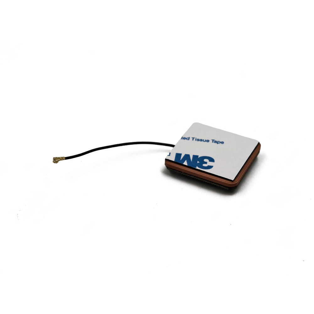
A Compact Active Ceramic Patch Antenna Module is a highly integrated, self-contained radio-frequency (RF) subsystem designed for superior reception of weak satellite signals. The term itself is descriptive of its nature:
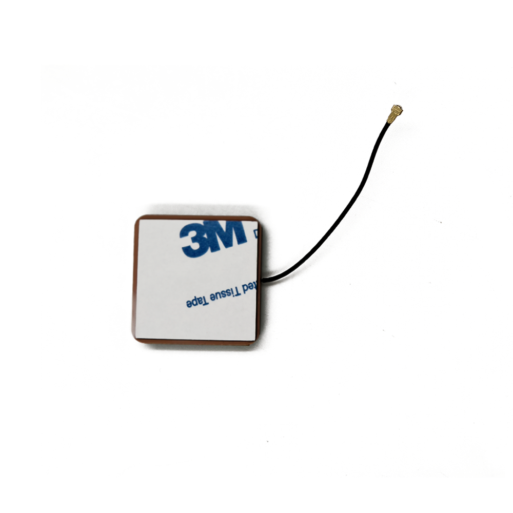
Compact: This is a key differentiator. The module is designed to occupy minimal physical volume, typically on the order of 10mm x 10mm x 4mm or smaller. This miniaturization is not merely a convenience; it is a strict requirement for integration into today's consumer electronics, wearables, drones, and IoT assets, where real estate on the printed circuit board (PCB) is fiercely contested.
Active: Unlike a passive antenna, which only captures and transmits electromagnetic waves, an active antenna incorporates electronic amplification directly at the point of reception. This activity is crucial because GNSS signals, after traveling over 20,000 kilometers from medium Earth orbit, are incredibly weak—often buried below the thermal noise floor of electronic systems. Amplification at the source is essential to overcome subsequent losses.
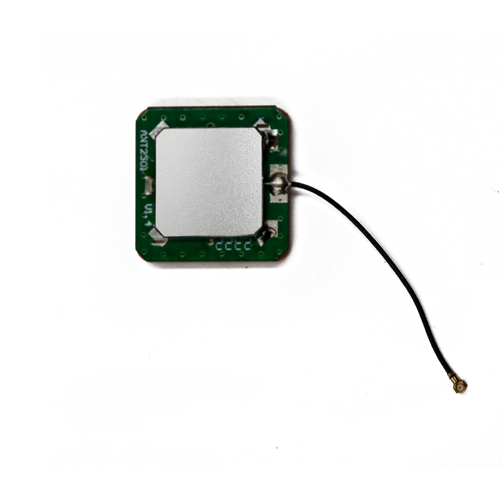
Ceramic Patch: This defines the core radiating element. The antenna is fabricated from a specialized ceramic material, typically a formulation based on barium strontium titanate, which possesses a very high dielectric constant (εr). This high εr is the secret to its compactness. It causes wavelength shortening within the material, allowing the physical dimensions of the antenna (which must resonate at a specific frequency) to be significantly reduced. The "patch" refers to its physical structure—a flat, rectangular or square metallized region on the ceramic surface.
Module: This signifies that the unit is not just a single component but a fully assembled system-in-a-package (SiP). It integrates the ceramic patch radiator, a low-noise amplifier (LNA), filtering components, impedance matching networks, and often a protective shield into a single, surface-mount device (SMD). This modularity simplifies design and manufacturing for original equipment manufacturers (OEMs).
The primary driver for the development of this technology is the challenge of receiving GNSS signals (from constellations like GPS, GLONASS, Galileo, and BeiDou) in small, portable, and often electrically noisy devices. A standalone passive antenna would be ineffective; the signal would be attenuated by the transmission line (coaxial cable or PCB trace) connecting it to the receiver, and the noise figure of the entire system would be prohibitively high. By integrating a high-gain, low-noise amplifier immediately after the radiating element, the module boosts the signal strength before any significant loss can occur. This practice preserves the signal-to-noise ratio (SNR), which is the most critical metric for receiver sensitivity and performance.
The typical architecture of such a module consists of three main functional blocks:
The Ceramic Patch Antenna: This element is responsible for resonating at the target GNSS frequencies (e.g., L1 band at 1575.42 MHz) and efficiently converting incoming electromagnetic waves into electrical signals. Its performance is characterized by its bandwidth, radiation pattern, gain, and efficiency.
The Low-Noise Amplifier (LNA): This semiconductor amplifier is the heart of the "active" functionality. It is designed to provide high gain (e.g., 15-28 dB) while introducing the absolute minimum amount of its own electronic noise, quantified by its Noise Figure (NF), which is typically below 1 dB for high-quality modules.
The Filtering and Matching Network: A band-pass filter, often a Surface Acoustic Wave (SAW) filter, is integrated to reject powerful out-of-band interference from other services like cellular (4G/5G), Wi-Fi, and Bluetooth. Impedance matching circuits ensure maximum power transfer between the antenna, the LNA, and the output to the receiver.
In essence, the compact active ceramic patch antenna module is a masterpiece of integration that solves a critical engineering problem. It transforms the daunting task of receiving femtowatt-level signals from space into a manageable one, enabling the tiny devices in our pockets and embedded in our infrastructure to know their precise location on Earth with remarkable accuracy. It is the unsung hero of the geolocation revolution.
The creation of a high-performance compact active ceramic patch antenna module is a sophisticated process that sits at the intersection of materials science, electromagnetic theory, semiconductor physics, and precision manufacturing. It involves a meticulous balancing act between competing parameters—size, bandwidth, efficiency, gain, and cost—to produce a robust and reliable component. This section delves into the materials, architectural decisions, and fabrication techniques that bring these modules to life.
The Ceramic Substrate and Patch Design:
The journey begins with the selection of the ceramic material. Engineers choose ceramic compositions (often based on titanium-based ceramics like barium strontium titanate) for their high dielectric constant (εr), which typically ranges from 20 to over 90. The primary advantage of a high εr is the drastic reduction in the physical size of the antenna for a given resonant frequency, as the wavelength within the dielectric is reduced by a factor of √εr. However, this benefit comes with significant trade-offs:
Bandwidth: A higher dielectric constant inherently results in a narrower impedance bandwidth. This is a major challenge as modern GNSS applications require support for multiple bands (L1, L2, L5, etc.) and constellations, necessitating a broader operational bandwidth.
Loss Tangent: Materials with very high εr often exhibit a higher loss tangent (tan δ), which translates to lower radiation efficiency as more energy is dissipated as heat within the ceramic itself rather than being radiated or received.
Temperature Stability: The dielectric constant of ceramics is temperature-sensitive. As the device operates and heats up, the material properties change, causing the antenna's resonant frequency to drift. This must be compensated for through material engineering or design margins.
The ceramic is precision-sintered and ground to exact dimensions. The metallization process applies a conductive layer (usually silver or copper) to the top and bottom surfaces. The bottom acts as the ground plane, while the top is patterned into the radiating patch element. The feed mechanism—how RF energy is coupled between the patch and the amplifier—is critical. Common methods include probe feeding (a conductive pin through the ceramic), aperture coupling (through a slot in the ground plane), and edge feeding. Each method offers different trade-offs in terms of bandwidth, spurious radiation, and ease of impedance matching.
The Active Circuitry: LNA and Filtering:
The active component is typically a monolithic microwave integrated circuit (MMIC) amplifier fabricated using Gallium Arsenide (GaAs) or advanced Silicon Germanium (SiGe) processes. These technologies are preferred over standard CMOS for their superior high-frequency performance and, crucially, their ability to achieve an exceptionally low Noise Figure (NF), often below 0.8 dB. The LNA is designed for a specific gain, balancing the need for strong signal amplification with the risk of overloading the subsequent receiver stages with too much power or interference.
Arguably as important as the LNA is the integrated filtering. A Surface Acoustic Wave (SAW) or Bulk Acoustic Wave (BAW) filter is placed in the signal chain, typically between the antenna and the LNA (to prevent strong interferers from saturating the amplifier) or between the LNA stages. This filter is sharply tuned to the GNSS bands and provides high rejection (often 30-40 dB or more) to powerful out-of-band signals from cellular, Wi-Fi, and other transmitters that coexist in modern devices.
Module Integration and Packaging:
The final assembly is where the "module" comes together. The ceramic antenna, the LNA/filter MMIC, and discrete components for the matching network and DC blocking are assembled onto a small, multi-layer laminate substrate, often made from a high-frequency material like Rogers RO4003® for its stable electrical properties. This substrate provides the interconnects and may also include a ground plane that extends beyond the ceramic antenna to enhance its performance.
A critical step is the precise tuning of the matching network. Using vector network analyzers, engineers adjust tiny capacitors and inductors to ensure optimal impedance matching between the antenna's output and the LNA's input across the desired frequency band. This maximizes power transfer and minimizes signal reflection (measured as Return Loss or VSWR).
Finally, the entire assembly is often encased in a metal shield can. This serves two vital purposes:
Electromagnetic Shielding: It protects the sensitive LNA from external radio frequency interference (RFI) and prevents the amplifier's output from radiating back into the device and causing issues.
Mechanical Protection: It provides a robust shell that protects the delicate ceramic and wire bonds during handling and reflow soldering.
The completed module is a hermetically sealed, surface-mount component that can be automatically placed and soldered onto a host PCB like any other integrated circuit. This construction process transforms complex RF engineering into a simple, reliable, and manufacturable commodity, hiding immense sophistication behind a deceptively simple exterior.
The operation of a compact active ceramic patch antenna module is a elegant sequence of signal transformation, from the faint whisper of a satellite transmission to a robust electrical signal ready for digital processing. Understanding this process reveals the engineering genius behind this seemingly simple component. The workflow can be broken down into four primary stages: reception, amplification, filtration, and delivery.
Stage 1: Reception and Electromagnetic Conversion (The Antenna Function)
The process initiates when electromagnetic waves transmitted by GNSS satellites impinge upon the ceramic patch element. These signals are right-hand circularly polarized (RHCP), a characteristic chosen for its resilience to signal degradation caused by atmospheric effects and reflections.
The ceramic patch is a resonant half-wave cavity. Its physical length is designed to be approximately half the wavelength of the target frequency within the dielectric material. Due to the high dielectric constant, this effective wavelength is much shorter than it would be in free space, enabling the small physical size. When the RF wave's frequency matches the patch's resonant frequency, it excites standing waves of current on the metallized surface. This resonance allows the antenna to efficiently convert the incident electromagnetic energy into a fluctuating voltage at its feed point. The antenna's performance is not isotropic; it has a specific radiation pattern, often with a broad, hemispherical view to maximize the sky coverage needed to "see" multiple satellites.
Stage 2: Pre-Amplification with Minimal Noise Degradation (The LNA Function)
The voltage signal generated at the feed point is extraordinarily weak, typically on the order of -130 dBm (0.1 femtowatts). This is below the thermal noise floor (approximately -111 dBm in a 2 MHz bandwidth) and would be unusable by any downstream receiver. Furthermore, if this signal were to travel through even a short length of lossy transmission line (e.g., a PCB trace with a loss of 2 dB), the signal would be attenuated, and the noise figure of the entire system would be degraded by that same 2 dB, according to Friis's formula.
This is the fundamental reason for the module's "active" nature. The weak signal is immediately routed to the input of the Low-Noise Amplifier (LNA), which is located just millimeters away. The LNA's primary job is to apply a high amount of gain (e.g., 20 dB) to this signal. Crucially, it must do this while adding the least possible amount of its own random electronic noise. This is quantified by its Noise Figure (NF). A perfect amplifier would have an NF of 0 dB, meaning the Signal-to-Noise Ratio (SNR) at its output is equal to the SNR at its input. A real-world LNA with an NF of 0.8 dB degrades the SNR by only that amount. By providing high gain at this first stage with a very low NF, the module effectively sets a low noise floor for the entire receiving system, ensuring that the amplified signal, now around -110 dBm, is dominated by the amplified satellite noise rather than the amplifier's own noise.
Stage 3: Interference Rejection (The Filtering Function)
The amplified signal now contains the desired GNSS energy but also carries amplified noise and, more dangerously, any interfering signals that the antenna also picked up. In a typical device, the GNSS module is located perilously close to powerful transmitters for cellular, Wi-Fi, and Bluetooth. A cellular transmission can be over 150 dB stronger than the GNSS signal. Without mitigation, these signals would easily drive the GNSS receiver chip into compression, blinding it to the desired satellite signals—a phenomenon known as desensitization or "blocking."
The integrated band-pass filter acts as a spectral gatekeeper. It is designed to have very low insertion loss within the specific GNSS frequency bands (e.g., 1559 – 1610 MHz) but very high attenuation (rejection) outside this range. It sharply attenuates strong out-of-band signals from cellular bands (700 MHz, 850 MHz, 1.9 GHz, etc.), Wi-Fi (2.4 GHz, 5 GHz), and other sources before they can cause harm. This protection is absolutely essential for reliable operation in real-world environments.
Stage 4: Signal Delivery and System Integration
The processed signal—now amplified, noise-controlled, and interference-filtered—is output from the module via a single RF port. The module typically requires a DC supply voltage (e.g., 2.7V to 3.3V) to power the LNA. This voltage is often supplied from the main GNSS receiver chip through the same coaxial cable used for the signal, using a circuit called a "bias tee."
The output signal is then fed to the input of the GNSS receiver IC. The receiver's job is to down-convert this RF signal, digitize it, and employ correlation algorithms to acquire and track the codes from multiple satellites, ultimately calculating Position, Velocity, and Time (PVT). The active antenna module's role is complete: it has successfully captured an incredibly weak signal from space, ensured its integrity, and delivered a clean, strong signal to the digital processor, thereby enabling the miracle of global navigation.
The widespread adoption of compact active ceramic patch antenna modules across countless industries is a direct testament to their compelling advantages. However, like any engineered solution, they are not without their inherent limitations and design challenges. A clear understanding of both their strengths and weaknesses is crucial for selecting and implementing them effectively.
Advantages:
Exceptional Miniaturization: This is the foremost advantage. The use of high-dielectric ceramic substrates allows for a drastically reduced footprint compared to traditional antennas like helices or patches on low-εr PCBs. This enables integration into increasingly space-constrained modern devices like smartphones, wearables, and miniature IoT sensors where every cubic millimeter counts.
High Performance and Superior Sensitivity: The integrated LNA provides critical gain at the very point of signal capture. This effectively pre-amplifies the weak GNSS signal before it can be degraded by losses in the transmission line to the receiver. The result is a significantly improved overall system Noise Figure, which translates directly into higher sensitivity. This allows devices to acquire and maintain a satellite lock in challenging environments with weak signals, such as under tree cover, in urban canyons, or indoors near a window.
Improved Resilience to Interference: The inclusion of a dedicated SAW or BAW filter within the module provides robust rejection of out-of-band interference. This is a critical feature in multi-radio devices where cellular, Wi-Fi, and Bluetooth transmitters can easily jam an unprotected GNSS receiver. The module acts as a first line of defense, preserving functionality.
Simplified Design-In Process for OEMs: The modular nature of the component is a major benefit for original equipment manufacturers. Instead of designing a custom passive antenna, a matching network, and a separate LNA circuit—tasks that require significant RF expertise—an engineer can simply place this pre-tuned, pre-matched module on the board. This dramatically reduces design complexity, development time, and risk, effectively "black-boxing" the complex RF section.
Mechanical Robustness and Manufacturing Consistency: As a single surface-mount component (SMD), it is highly suitable for automated pick-and-place assembly, ensuring manufacturing consistency and reliability. The ceramic construction and shielded package make it resistant to vibration, shock, and environmental contaminants, outperforming more fragile external antenna designs.
Challenges and Limitations:
Performance Dependency on Host Board Design: This is arguably the most significant challenge. While the module itself is engineered for performance, its efficacy is heavily influenced by the host device's PCB. The size and shape of the ground plane on the host board are critical, as the ceramic patch antenna uses it as a counterpoise. A small or irregular ground plane can severely detune the antenna, distort its radiation pattern, and reduce its efficiency. The module cannot be treated as an isolated component; it must be designed into the system with care.
Susceptibility to In-Band Interference and Desense: While the filter handles out-of-band noise, it is transparent to in-band interference. Noise generated within the GNSS band itself can still be problematic. This can come from harmonic emissions of other digital clocks on the board, switching power regulators, or poorly shielded processors. If this noise is picked up by the antenna or couples into the RF output line, it can desensitize the receiver. Careful system-level design, layout, and shielding are still required.
Inherent Bandwidth Limitations: The high dielectric constant that enables miniaturization also physically limits the achievable impedance bandwidth. Designing a single ceramic patch that efficiently covers all modern GNSS bands (L1, L2, L5, etc.) is a major engineering challenge. Often, designs are optimized for the core L1 band, with performance on secondary bands being acceptable but not optimal.
Thermal Drift: The dielectric constant of ceramic materials changes with temperature. As the device operates and its internal temperature rises (e.g., from the cellular modem or processor), the resonant frequency of the ceramic antenna can shift. If this drift is significant, it can move the operating frequency outside the optimal band, leading to a degradation in performance.
Cost: While prices have fallen with mass adoption, an active ceramic module is still more expensive than a simple passive PCB trace antenna or an external antenna. The cost includes the specialized ceramic material, the GaAs MMIC, the SAW filter, and the assembly and tuning process. For ultra-cost-sensitive applications, this can be a deciding factor.
In summary, the advantages of size, performance, and integration ease make these modules the ideal choice for the vast majority of consumer and industrial GNSS applications. However, successful implementation requires a respectful awareness of their limitations, particularly their dependence on a well-designed host environment to achieve their specified performance.
The compact active ceramic patch antenna module is not a technology developed in isolation; it is an enabling component that has found its way into the heart of a breathtakingly wide array of applications. Its unique value proposition—high performance in a tiny, integrable form factor—has made it indispensable to the global push for connectivity and location intelligence. Concurrently, ongoing technological advancements are continuously expanding its capabilities and opening new frontiers.
Current Applications:
Consumer Electronics: This is the highest-volume application domain.
Smartphones and Tablets: Ubiquitous for navigation apps, location-based services, geotagging, and emergency services (E911).
Wearable Devices: Fitness watches, sports bands, and pet trackers use these modules for accurate distance, pace, and route tracking without tethering to a phone.
Cameras and Drones: Drones rely on GNSS for stabilization, autonomous flight, navigation, and return-to-home functions. Action and digital cameras use it for geotagging photos and videos.
Personal and Asset Trackers: Compact modules are ideal for tracking children, elderly people, pets, luggage, and high-value assets in logistics.
Automotive and Telematics:
Telematics Control Units (TCUs): The core of modern fleet management, usage-based insurance (UBI), and stolen vehicle recovery systems. They track location, speed, idling time, and harsh driving events.
In-Vehicle Infotainment (IVI) Systems: Provide turn-by-turn navigation and connected services.
Advanced Driver-Assistance Systems (ADAS): GNSS data is a key sensor input for ADAS features, providing absolute location and velocity data that is fused with camera, radar, and lidar data for functions like adaptive cruise control and collision avoidance. It is a critical component for future autonomous vehicles.
Industrial IoT and Machine-to-Machine (M2M) Communication:
Smart Agriculture: Precision farming equipment uses GNSS for guided steering, variable rate application of water/fertilizers/pesticides, and yield mapping.
Asset Monitoring: Tracking of shipping containers, railway cars, and industrial equipment across global supply chains.
Time Synchronization: Providing precise timing for network infrastructure, financial transactions, and energy grid management.
Micro-Mobility: Electric scooters and bikes use embedded GNSS modules for fleet management for rental companies, implementing geofencing to control parking areas, and providing anti-theft functionality.
Future Trends:
Multi-Band/Multi-Constellation Support as Standard: The future is undeniably multi-frequency (L1 + L5/E5a) to enable centimeter-level accuracy using advanced correction techniques like Real-Time Kinematics (RTK) and Precise Point Positioning (PPP). Future modules will be designed from the ground up to support wide bandwidths and multiple resonant modes efficiently, moving beyond being primarily L1-optimized.
Integration with Other Technologies (AiP and RF Front-End Modules): The trend toward greater integration will continue. We will see the rise of Antenna-in-Package (AiP) technology, where the ceramic antenna is integrated directly into the package of the GNSS receiver SoC (System on a Chip) or a larger RF Front-End Module (FEM) that also handles cellular connectivity. This will further reduce size, simplify design, and improve performance by eliminating interconnects.
Intelligent and Adaptive Systems: Future modules may incorporate a degree of intelligence. This could include built-in interference detection and mitigation circuitry that can dynamically filter or notch out jamming signals. Systems could also use multiple antennas (diversity) and algorithms to select the best signal or even perform basic beamforming to null out interference sources.
Enhanced Robustness and Security: As society becomes more dependent on GNSS, its vulnerability to jamming and spoofing becomes a greater concern. Future modules may incorporate features to harden against these attacks, perhaps through cryptographic authentication of signals or more advanced signal processing techniques to identify and reject malicious transmissions.
Focus on Ultra-Low Power Consumption: For the massive IoT market, where devices must run on batteries for years, power consumption is paramount. The next generation of LNAs will be optimized for ultra-low-power operation, potentially incorporating advanced power-gating techniques that only activate the amplifier when a signal is present, drastically extending battery life.
The compact active ceramic patch antenna module will continue to evolve from a simple receiver into a smarter, more integrated, and more robust subsystem. It will remain a fundamental building block for the next wave of technological innovation, enabling everything from fully autonomous transportation to a truly seamless and intelligent IoT ecosystem.
Conclusion
The compact active ceramic patch antenna module is a paradigm of modern engineering—a deceptively simple component that encapsulates a profound solution to a complex problem. It represents the culmination of advancements in materials science, semiconductor technology, and electromagnetic design, all focused on the singular goal of reliably connecting our Earth-bound devices to the faint signals from satellites in medium Earth orbit. Its development and proliferation have been a critical enabler of the location-aware revolution, transforming GNSS from a specialized tool into a ubiquitous utility.
As we have seen, its core value lies in its elegant integration. By marrying a miniaturized ceramic radiator with a low-noise amplifier and protective filtering into a single, surface-mount package, it solves the primary challenges of GNSS reception in small form-factor devices: weak signal strength, transmission line loss, and a noisy RF environment. This integration offers OEMs the priceless advantages of miniaturization, superior sensitivity, design simplification, and mechanical robustness, which explains its dominance in consumer and industrial markets.
However, this integration does not equate to autonomy. The module's performance is inextricably linked to its host environment. Its efficiency and bandwidth are deeply influenced by the PCB's ground plane, and its success can be compromised by poor system design that allows internal interference to run rampant. Therefore, it is not a magic bullet but a high-performance component that demands respectful and knowledgeable implementation.
Looking forward, the trajectory of this technology is clear. It will evolve to support the demanding requirements of high-precision navigation through multi-band capabilities, become even more deeply integrated into SoCs and RF modules, and grow smarter with features aimed at combating interference and improving power efficiency. It will continue to be a vital gateway to the GNSS constellations, forming a foundational pillar for the next generation of autonomous systems, smart cities, and the ever-expanding Internet of Things.
In conclusion, the compact active ceramic patch antenna module is far more than just an antenna. It is a sophisticated, self-contained RF subsystem that has democratized access to precise positioning and timing. It is a testament to the power of integration and a key technology that has quietly helped to weave location intelligence into the very fabric of our digital lives. Its continued evolution will be essential in navigating the challenges and opportunities of our connected future.

 86 0755 2819 9597
Lucy Yang | lucy.y@toxutech.com
Nicole Li | nicole@toxutech.com
Dotty Zhao | sales04@toxutech.com
Global Business Director / Sales Team / Global Operations


 En
En Cn
Cn Korean
 Home >


