

-
Products -PCBA Manufacturing RF Connectors RF Cable Assemblys Embedded Antennas External Antennas Positioning Chips and Modules
RF Connectors

RF Cable Assemblys
Embedded Antennas
External Antennas
Positioning Chips and Modules


 Language


Language


Precision is the absolute cornerstone of surveying, mapping, and geomatics. The difference of a few centimeters can determine a property boundary, the alignment of a critical infrastructure project, or the volumetric calculation of a mine. While consumer-grade GPS can provide meter-level accuracy, the professional world demands far greater precision. This is where Real-Time Kinematic (RTK) technology enters the picture, capable of delivering centimeter-level accuracy in real-time. At the heart of any high-precision RTK system is its antenna, and the built-in ceramic patch antenna has become a dominant, albeit highly specialized, component in modern surveying equipment.
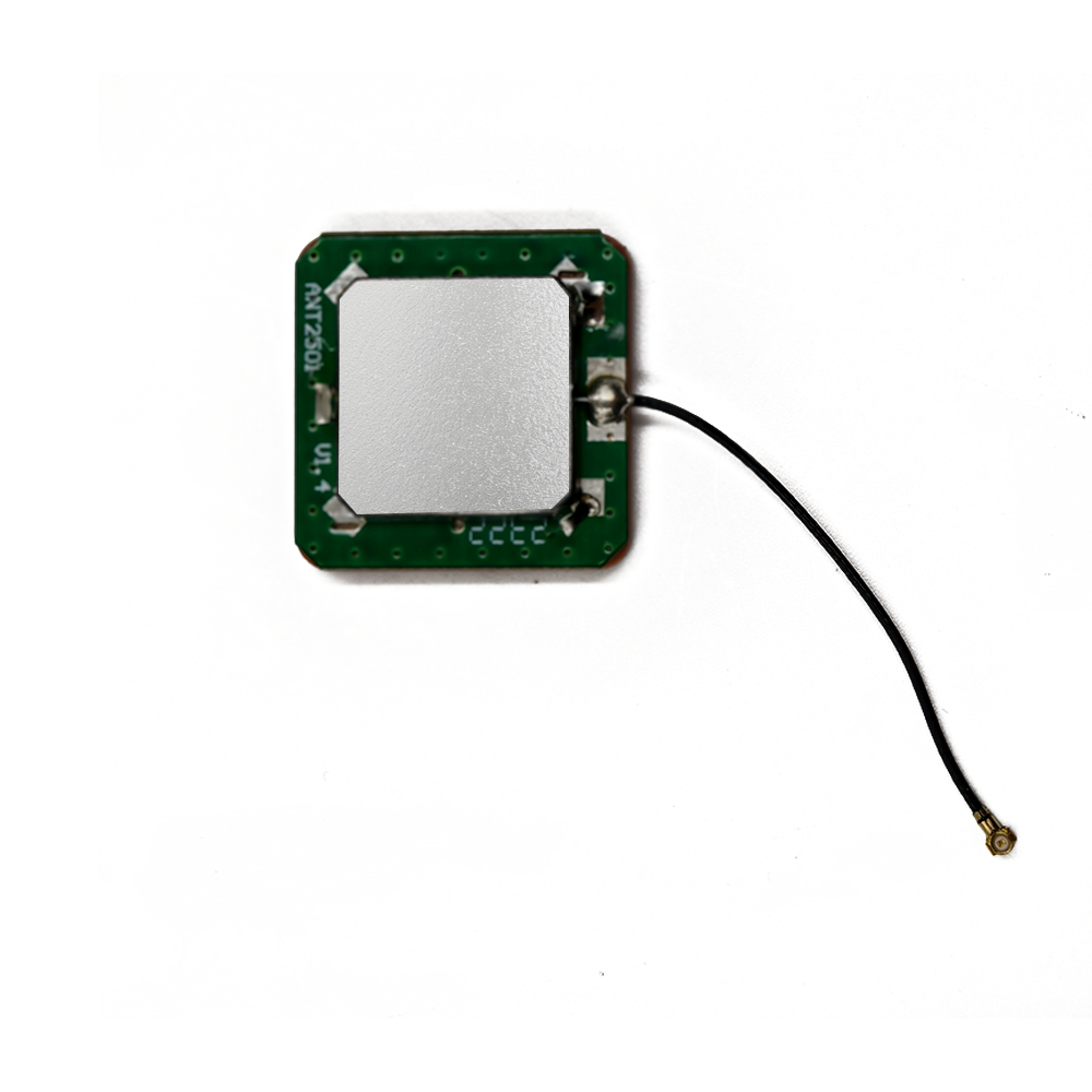
An RTK GPS ceramic antenna is not merely a larger version of the antenna found in a smartphone. It is a precision instrument engineered to meet the extreme demands of high-accuracy positioning. The term "built-in" signifies its integration into the housing of a surveying device, such as a GNSS rover or base station, as opposed to being an external, add-on component. This integration is crucial for creating a robust, portable, and reliable system for field use. The "ceramic" refers to the high-dielectric substrate material that allows the antenna's physical size to be manageable while resonating at the relatively long wavelengths of satellite navigation signals (19 cm for the GPS L1 frequency).
The primary function of this antenna is to act as the first and most critical stage in the signal reception chain. It is responsible for efficiently capturing the incredibly weak electromagnetic signals transmitted from multiple Global Navigation Satellite System (GNSS) constellations—including GPS (USA), GLONASS (Russia), Galileo (EU), and BeiDou (China)—across multiple frequency bands (e.g., L1, L2, L5, E1, E5a, E5b, B1, B2). However, for RTK, the antenna's role goes beyond simple reception. Its performance directly dictates the system's ability to resolve the integer ambiguities in the carrier phase measurements—the fundamental technique that enables centimeter accuracy. Any imperfection in the antenna's phase center, its ability to reject multipath interference, or its stability across frequencies introduces error into these measurements, thus degrading the final positional accuracy.
The evolution of these antennas parallels the advancement of surveying technology itself. Early high-precision GPS required large, heavy, choke-ring antennas. These were excellent at mitigating multipath (signals reflecting off the ground or nearby objects) but were utterly impractical for mobile field use. The development of advanced ceramic patch antennas offered a path to miniaturization without a complete sacrifice of performance. Modern built-in RTK antennas are the result of decades of refinement in electromagnetic design, materials science, and manufacturing, packing the performance once reserved for large geodetic antennas into a compact, ruggedized form factor that can be mounted on a surveyor's pole.
A key differentiator for an RTK antenna is its focus on phase center stability. Unlike amplitude-based measurements (how strong the signal is), RTK relies on measuring the phase of the carrier wave itself, which is akin to measuring the distance to the satellite with a ruler that has marks every 19 centimeters. The electrical point from which these phase measurements are referenced is called the phase center. In a perfect antenna, this point would be a fixed, unchanging location. In reality, it varies with the direction (azimuth and elevation) of the incoming satellite signal and its frequency. A high-quality surveying antenna is meticulously designed to minimize this variation, ensuring that the measurements for a satellite directly overhead and one near the horizon are referenced from as consistent a point as possible. This stability is paramount for achieving rapid and reliable integer ambiguity resolution.
In summary, the built-in RTK GPS ceramic antenna is the unsung hero of modern high-precision surveying. It is a sophisticated sensor that transcends the basic role of signal collection. Its design is a complex balancing act between physical size, multi-frequency performance, phase stability, and multipath rejection, all aimed at providing the cleanest, most stable signal possible to the RTK receiver. This enables surveyors, engineers, and scientists to achieve unprecedented levels of accuracy and efficiency in the field, forming the foundation for the data that builds our world.
The design and construction of a built-in RTK GPS ceramic antenna is a feat of precision engineering, involving a multi-layered approach where every material, dimension, and component is optimized for electromagnetic purity and stability rather than simply for miniaturization or cost.
The Core: High-Performance Ceramic Substrate
The foundation is a high-purity ceramic substrate, typically based on alumina (Al2O3) or more advanced proprietary blends. For surveying antennas, the dielectric constant (εr) is carefully chosen not just for size reduction but for optimal bandwidth and efficiency. While consumer antennas may use very high-εr ceramics (>30) for extreme miniaturization, surveying antennas often use moderate-εr materials (e.g., 20-25) to achieve a better balance, resulting in a larger patch but with wider bandwidth and lower losses. The substrate's thickness is also a critical parameter; a thicker substrate provides wider bandwidth, which is essential for supporting multiple GNSS bands, but it can also increase the antenna's profile and weight.
The Radiating Element: Precision Patch Design
The metallic radiating patch is photolithographically etched or printed onto the ceramic surface with extreme precision. Its geometry is far more complex than a simple square.
Multi-Frequency Operation: To receive all necessary signals (L1, L2, L5, etc.), the single patch is often engineered with slots, notches, or other perturbations. These features create multiple current paths, allowing the single element to resonate at several fundamental and harmonic frequencies simultaneously. Alternatively, a stacked patch design is used, where a second, slightly larger patch is placed above the primary one, separated by a second dielectric layer. Each patch is tuned to a different frequency band (e.g., the lower patch for L2, the upper for L1).
Circular Polarization Purity: Achieving near-perfect Right-Hand Circular Polarization (RHCP) is paramount. This is often accomplished using a single feed point with a carefully designed asymmetric geometry (like truncated corners) or, more commonly in high-end designs, a dual-feed system. In a dual-feed antenna, the patch is excited at two orthogonal points. An external or internal 90° hybrid coupler then ensures the signals at these points are exactly 90 degrees out of phase, generating exceptionally pure circular polarization, which is vital for multipath rejection.
The Ground Plane and Multipath Mitigation
A extensive, high-conductivity ground plane is located beneath the ceramic substrate. Its size and quality are crucial for defining the antenna's radiation pattern. A larger ground plane helps to push the pattern's peak gain upward and reduces sensitivity to signals arriving from low elevations (which are more likely to be multipath). The most significant innovation in surveying antenna design is the integration of multipath mitigation technology directly into the ground plane structure. This often takes the form of a Frequency Selective Surface (FSS) or a simplified "choke-ring" structure built into the antenna housing itself. These structures consist of concentric rings or a patterned surface that presents a high impedance to reflected signals (which typically have shallow elevation angles), effectively "choking" them out, while being transparent to the direct signals from satellites overhead.
The Phase Center and Calibration
The most critical aspect of the design is ensuring Phase Center Stability (PCS). Engineers use advanced 3D electromagnetic simulation software (e.g., ANSYS HFSS, CST) to model the antenna's performance from every possible angle of arrival. The goal is to minimize the Offset and Variation of the Phase Center (PCO and PCV). After manufacture, high-end antennas undergo rigorous robotic testing in an anechoic chamber. Here, a precise robotic arm measures the antenna's phase response from every direction across all frequencies. This data is used to generate a phase center calibration model, a table of corrections that the RTK receiver software can apply to each measurement based on the satellite's elevation and azimuth, effectively compensating for the antenna's inherent imperfections.
Construction and Integration
The entire assembly—ceramic substrate, patch element, ground plane, and often the feed network—is laminated and sintered into a robust, monolithic block. This is then housed in a ruggedized plastic or composite radome. The radome is designed to be environmentally sealed (IP67 or higher) to protect against water, dust, and shock. It is also electrically designed to have minimal impact on the antenna's performance. The Low-Noise Amplifier (LNA) is a critical integrated component, chosen for its ultra-low noise figure (<1 dB) and high linearity to handle strong out-of-band signals without distortion. The entire unit is designed to be precisely mounted within the survey instrument, with its mechanical and electrical reference points clearly defined for the user.
The working principle of an RTK ceramic antenna extends far beyond basic signal reception; it is about the faithful preservation of the carrier wave's phase information, which is the key to centimeter-level accuracy.
The Foundation: Capturing the Carrier Phase
GPS and other GNSS satellites transmit two types of ranging codes: the Coarse/Acquisition (C/A) code and the Precision (P) code. While code-based measurements can provide meter-level accuracy, the real magic of RTK lies in measuring the phase of the underlying carrier wave itself. The L1 carrier, for instance, has a wavelength of approximately 19 cm. By precisely measuring the phase of this carrier, the receiver can measure the distance to the satellite with a precision of a small fraction of this wavelength—potentially down to 1-2 millimeters. However, there's an initial ambiguity: the receiver can measure the fractional part of the wavelength but does not know the integer number of full wavelengths between the satellite and itself. Resolving this integer ambiguity is the core challenge of RTK.
The Antenna's Role in the RTK Engine
The antenna is the starting point for this entire process. Its job is to deliver a clean, stable signal to the receiver so it can perform two crucial tasks:
Maintaining Lock: The receiver must maintain continuous, uninterrupted lock on the carrier phase of each satellite. Any loss of lock resets the integer ambiguity for that satellite. The antenna facilitates this by providing a strong, stable signal with high gain, even at low elevation angles, and by aggressively rejecting multipath that could cause the receiver's phase-locked loops (PLLs) to slip or lose track.
Providing a Stable Reference Point: All phase measurements are made relative to the antenna's electrical phase center. If this phase center were to move depending on the satellite's position, it would introduce error into the measurement. The antenna's design goal is to make this phase center as stable and predictable as possible. The calibration model applied by the receiver software is a set of corrections that virtually "moves" all measurements to a single, consistent ARP (Antenna Reference Point), usually the physical bottom of the antenna mount.
Multipath Rejection in Action
Multipath occurs when a satellite's signal takes an indirect path to the antenna, reflecting off the ground, buildings, or other objects. This reflected signal arrives slightly later than the direct signal and, crucially, often has reversed polarization (becoming LHCP). The antenna combats this through two primary mechanisms:
Radiation Pattern Shaping: The antenna is designed to have very low gain at negative elevation angles (below the horizon). Since multipath signals usually arrive from these low angles, they are naturally attenuated.
Polarization Filtering: The antenna's pure RHCP characteristic acts as a filter. The direct signal from the satellite is RHCP and is received efficiently. When this signal reflects off a surface, its polarization often reverses to become predominantly LHCP. The RHCP antenna is inherently less sensitive to LHCP signals, thus rejecting a large portion of the multipath energy.
The Multi-Constellation, Multi-Frequency Advantage
Modern RTK antennas are designed to receive all signals from all available constellations and frequencies. This provides massive advantages:
More Satellites: More visible satellites improve the geometric strength of the solution (lower PDOP - Position Dilution of Precision), leading to better accuracy and availability, especially in obstructed environments.
Faster Ambiguity Resolution: Using multiple frequencies allows for the creation of extra-wide-lane combinations. These combinations have very long wavelengths (e.g., 86 cm for the wide-lane between GPS L1 and L2), making the integer ambiguity much easier and faster to resolve, even when on the move (kinematic surveying).
Ionospheric Error Correction: The ionosphere delays signals, an error that is frequency-dependent. By measuring the same signal on two different frequencies (e.g., L1 and L2), the receiver can directly calculate and eliminate most of the ionospheric delay, a dominant source of error in single-frequency systems.
In essence, the antenna works by acting as a spatially and polarization-selective filter for space. It preferentially admits direct, line-of-sight signals from satellites above the horizon while suppressing noise, interference, and reflected multipath signals. It does this consistently across a wide range of frequencies and from all directions, providing the receiver with the pristine raw data it needs to perform the mathematical feat of integer ambiguity resolution and deliver a centimeter-accurate position.
The integration of a high-performance ceramic antenna directly into an RTK surveying system offers a compelling set of advantages that have driven its widespread adoption, but it also introduces specific challenges that manufacturers and users must navigate.
Advantages:
Compact and Integrated Form Factor: The primary advantage is the creation of a single, unified instrument. There are no external cables, separate antennas, or additional mounting hardware to manage, transport, or fail. This greatly enhances portability, simplifies setup, and reduces the risk of damage or connection issues in the field. The surveyor simply powers on the pole and begins working.
Optimized System Performance: Because the antenna and receiver are designed together as a system, the manufacturer can perfectly match the antenna's performance characteristics to the receiver's requirements. The LNA gain and noise figure can be optimized, and the receiver can be pre-loaded with the exact phase center calibration model for that specific antenna, ensuring the highest possible accuracy out of the box.
Robustness and Environmental Sealing: A built-in antenna is protected within a ruggedized housing. The entire unit is typically rated to high IP standards (e.g., IP67), making it waterproof, dustproof, and resistant to the shocks and vibrations encountered in harsh field environments. This is far more reliable than a system with external cables and connectors, which are common points of failure.
Consistency and Ease of Use: The system eliminates user error related to antenna setup. There is no risk of mis-measuring the height of an external antenna above a survey point (Antenna Height Reference Error), as the ARP is a fixed, known point on the integrated pole. This simplifies procedures and improves measurement consistency across different crews.
Effective Multipath Suppression: Modern built-in antennas incorporate advanced ground plane designs (like embedded choke rings or FSS) that are highly effective at suppressing ground-plane multipath. This provides performance that, while not quite matching a large geodetic choke ring, far surpasses that of a simple patch antenna on a flat ground plane.
Challenges and Limitations:
The Compromise on Ultimate Performance: The laws of physics present a fundamental challenge. The most effective multipath mitigation technology, the large ground-plane choke ring, is physically incompatible with a compact, portable design. While built-in designs use clever techniques to approximate its performance, they cannot fully equal the supreme multipath rejection of a large, professional-grade external choke ring antenna, especially in highly reflective environments (e.g., near steel-framed buildings or fencing).
Thermal Management: The antenna module, and particularly the LNA, generates heat. When sealed inside a housing with the receiver electronics, managing this heat becomes a challenge. Temperature variations can cause slight shifts in the electrical properties of the components, potentially affecting the phase center stability. High-end designs use careful layout and materials to mitigate thermal drift.
Limited Upgradeability: In a system with an external antenna, a surveyor can upgrade the antenna or the receiver independently. With a built-in design, the system is a closed unit. If a new GNSS signal becomes available or a significantly better antenna technology emerges, the entire unit must be replaced instead of just a single component.
Potential for Internal Interference: Cramming a sensitive analog RF antenna in close proximity to a powerful digital receiver creates potential for electromagnetic interference (EMI). The digital noise from the receiver's processors and clocks can easily desensitize the front-end LNA if not meticulously shielded. This requires excellent internal shielding, filtering, and PCB layout design, which adds to the complexity and cost.
Cost: The research, development, and precision manufacturing required for a high-performance, calibrated, multi-frequency antenna are significant. Integrating it with a receiver further adds to the unit's cost. While the total system cost may be comparable to a separate antenna-and-receiver setup, the initial investment for the integrated unit is higher.
Calibration Dependency: The system's accuracy is entirely dependent on the factory-loaded phase center model. If the antenna is damaged or the internal characteristics drift over time (though this is rare), the user has no way to re-calibrate it. The system must be returned to the manufacturer, whereas an external antenna can simply be swapped out.
Built-in RTK GPS ceramic antennas have revolutionized data collection workflows across numerous industries that rely on centimeter-accurate positioning. Their application is defined by the need for high precision combined with operational efficiency and mobility.
Applications:
Construction Site Layout and Machine Control: Surveyors use RTK rovers to precisely stake out the locations of foundations, walls, and columns from digital design plans. Furthermore, these antennas are integrated into bulldozers, graders, and excavators for machine guidance and control, automatically guiding blades and buckets to the correct grade without the need for traditional grade stakes.
Precision Agriculture: Agricultural RTK systems guide tractors with 2-3 cm accuracy for automated planting, spraying, and harvesting. This enables practices like variable rate application (applying seed, fertilizer, or pesticide only where needed), reducing waste and increasing yields. The rugged, integrated design is essential for the dusty, vibrating environment of a farm.
Cadastral and Topographic Surveying: This is the traditional core of surveying. RTK systems are used to establish national grids, mark property boundaries, and create highly detailed topographic maps of the land's surface for engineering and design projects. The portability of the integrated pole allows surveyors to access difficult terrain.
Utility Mapping and GIS: For mapping the location of underground assets (gas lines, water valves, fiber optic cables), the speed and accuracy of RTK are invaluable. GIS professionals use it to accurately attribute geographic data in the field.
Monitoring and Deformation Analysis: Networks of RTK receivers (often base stations) with stable antennas are used to monitor minute movements of critical infrastructure like dams, bridges, volcanoes, and landslides over time, providing early warning of potential failures.
Drone-Based Photogrammetry and Lidar: Integrated, lightweight RTK antennas are mounted on Unmanned Aerial Vehicles (UAVs). They provide precise geotagging for each aerial photograph or lidar point, creating highly accurate orthomosaics and 3D models without the need for numerous ground control points.
Future Trends:
Towards Full-Band, Multi-Constellation Support: The future is "all signals, all constellations." Next-generation antennas will need to support all current and planned signals, including the new L1C, L2C, and L5 from GPS, and similarly modernized signals from other constellations. This demands even wider bandwidth designs and more sophisticated multi-resonant patch structures.
Tighter Integration with Inertial Navigation Systems (INS): The fusion of GNSS with Inertial Measurement Units (IMUs) is becoming standard for mobile mapping. The trend is towards deeply integrated GNSS-INS systems within a single housing, providing continuous centimeter-level positioning even during short GNSS outages (under bridges, in tunnels, under tree cover). The antenna's stability is critical for calibrating the IMU in real-time.
AI-Enhanced Multipath Mitigation: Future systems may incorporate artificial intelligence to analyze the signal characteristics in real-time and identify and filter out multipath that manages to bypass the antenna's physical mitigation techniques, further improving accuracy in challenging urban canyons.
Miniaturization for New Platforms: As robotics and autonomous systems advance, there will be a push to further miniaturize high-precision antennas for integration into smaller platforms like delivery robots, augmented reality headsets, and even consumer devices for emerging applications.
Cloud-Based Calibration and Corrections: The phase center calibration model could become a dynamic, cloud-based service. The antenna could report its serial number to a correction service, which would then stream a tailored, potentially even real-time refined, calibration model to the receiver in the field, pushing the boundaries of accuracy.
Resilience to Jamming and Spoofing: As reliance on GNSS grows, so do threats from intentional jamming (blocking signals) and spoofing ( broadcasting fake signals). Future antenna designs may incorporate adaptive null-steering capabilities to automatically null out interference sources, protecting the integrity of the positioning solution.
Conclusion
The built-in RTK GPS ceramic antenna represents a pivotal convergence of precision electromagnetics and practical field engineering. It is a component that has been elevated from a simple receiver to a calibrated, mission-critical sensor, forming the foundation upon which the entire edifice of modern high-accuracy positioning is built. Its development and refinement have been directly responsible for transforming RTK from a complex, cumbersome technique used only by specialists into a accessible, reliable, and efficient tool deployed daily across countless industries.
The core achievement of this technology is its successful reconciliation of the inherent conflict between performance and portability. While it acknowledges that a compromise must be made against the gold standard of a large geodetic antenna, it minimizes this compromise through intelligent design, advanced materials, and sophisticated calibration. The result is a system that delivers superlative performance—characterized by exceptional phase center stability, superior multipath rejection, and multi-frequency capability—in a package that is rugged, portable, and simple to use.
The advantages of integration—eliminating cabling, reducing setup time, minimizing user error, and ensuring a perfectly matched system—have proven overwhelmingly valuable for the vast majority of field applications. This has democratized centimeter-accurate positioning, empowering not just surveyors but also farmers, construction workers, and GIS professionals to perform their work with unprecedented levels of efficiency and confidence.
Looking forward, the role of the built-in antenna will only grow more critical. The insatiable demand for higher accuracy, faster initialization times, and more reliable operation in challenging environments will continue to drive innovation in materials science, electromagnetic design, and signal processing. The trends towards full-band support, deep INS integration, and AI-powered enhancement are not mere incremental improvements but are steps towards creating ever more robust and intelligent positioning systems. The built-in RTK ceramic antenna, though hidden from view, will remain the silent, stable, and precise foundation upon which the future of autonomous systems and the digitally-mapped world is constructed.

 86 0755 2819 9597
Lucy Yang | lucy.y@toxutech.com
Nicole Li | nicole@toxutech.com
Dotty Zhao | sales04@toxutech.com
Global Business Director / Sales Team / Global Operations


 En
En Cn
Cn Korean
 Home >


