

-
Products -PCBA Manufacturing RF Connectors RF Cable Assemblys Embedded Antennas External Antennas Positioning Chips and Modules
RF Connectors

RF Cable Assemblys
Embedded Antennas
External Antennas
Positioning Chips and Modules


 Language


Language


In the rapidly evolving landscape of automotive technology, the demand for precise positioning has become a cornerstone of advanced driver assistance systems (ADAS), autonomous driving (AD), and connected car services. Among the technologies enabling high-precision positioning, Real-Time Kinematic (RTK) stands out for its ability to deliver centimeter-level accuracy, a leap beyond the meter-level precision of standard Global Navigation Satellite System (GNSS) receivers. The automotive multi-band RTK car antenna solution emerges as a critical component in this ecosystem, designed to overcome the limitations of single-band antennas and unlock the full potential of RTK technology for vehicles.
To understand the significance of this solution, it is first essential to define its core components and purpose. A multi-band RTK car antenna is a specialized device that receives signals from multiple frequency bands of GNSS constellations—such as GPS (L1, L2, L5), GLONASS (G1, G2, G3), Galileo (E1, E5a, E5b), and BeiDou (B1, B2, B3)—and works in tandem with an RTK receiver to correct positioning errors in real time. Unlike single-band antennas, which rely on a single frequency and are vulnerable to signal interference, multipath effects, and atmospheric disturbances, multi-band antennas leverage multiple frequencies to mitigate these issues, ensuring more reliable and accurate positioning even in challenging environments.
The development of automotive multi-band RTK antennas is driven by two key trends: the advancement of autonomous driving and the growing need for connected mobility services. For autonomous vehicles (AVs), centimeter-level positioning is non-negotiable—whether for navigating narrow urban streets, merging onto highways, or avoiding obstacles. Standard GNSS receivers often fail to meet this requirement due to errors caused by ionospheric delay (a major source of positioning inaccuracy, as ionized particles in the upper atmosphere distort satellite signals) and multipath (where signals reflect off buildings, trees, or other objects before reaching the antenna, leading to timing errors). Multi-band RTK antennas address these challenges by using multiple frequencies to model and cancel out ionospheric delays, while their design minimizes multipath interference.
Another driver of adoption is the expansion of smart city infrastructure and vehicle-to-everything (V2X) communication. In smart cities, vehicles need to interact with traffic lights, road sensors, and other infrastructure to optimize traffic flow and enhance safety. This interaction requires precise positioning to ensure that vehicles can accurately report their location and receive context-aware alerts. Multi-band RTK antennas provide the reliability needed for V2X systems, even in dense urban canyons where satellite signal visibility is limited.
Additionally, the rise of electric vehicles (EVs) and fleet management solutions has increased the demand for accurate tracking and monitoring. Fleet operators rely on precise positioning to optimize routes, reduce fuel consumption (or EV battery usage), and improve driver safety. Multi-band RTK antennas enable real-time tracking with centimeter-level accuracy, allowing fleet managers to make data-driven decisions and enhance operational efficiency.
It is also important to contextualize the multi-band RTK solution within the broader GNSS ecosystem. As global constellations like Galileo and BeiDou continue to expand their coverage and add new frequency bands, multi-band antennas are well-positioned to leverage these advancements. For example, Galileo’s E5a and E5b bands are designed specifically for high-precision applications, offering better resistance to interference and improved accuracy compared to older bands like GPS L1. By supporting multiple constellations and bands, automotive multi-band RTK antennas ensure redundancy—if one constellation or band is disrupted (e.g., due to weather or jamming), the antenna can switch to another, maintaining continuous positioning.
In summary, the automotive multi-band RTK car antenna solution is a vital enabler of next-generation automotive technologies. Its ability to deliver centimeter-level accuracy, resist interference, and operate in challenging environments makes it indispensable for ADAS, autonomous driving, V2X communication, and fleet management. As the automotive industry continues to move toward greater automation and connectivity, the role of multi-band RTK antennas will only grow, driving innovation and improving the safety, efficiency, and reliability of vehicles worldwide.
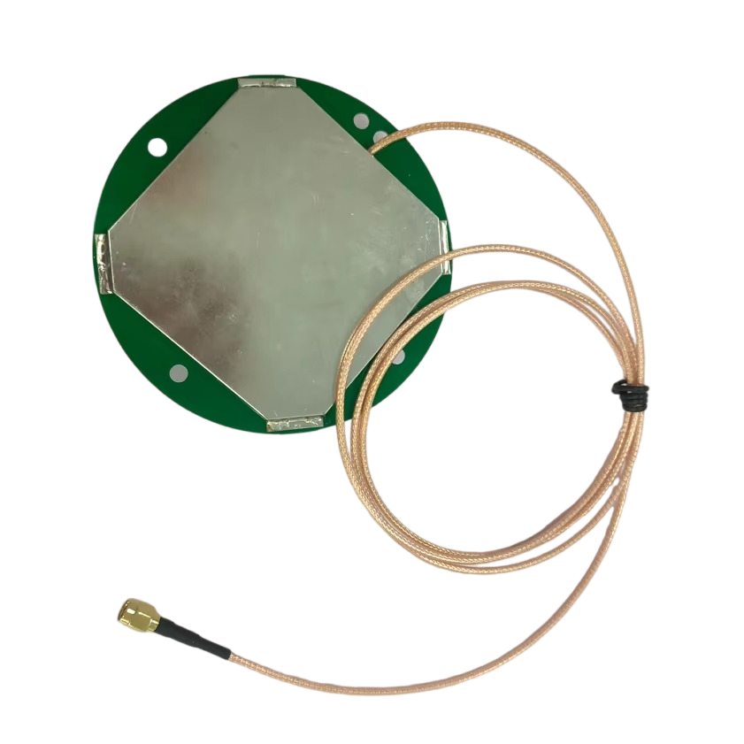
The design and construction of an automotive multi-band RTK car antenna are engineered to meet the stringent requirements of high-precision positioning, durability in harsh automotive environments, and compatibility with multiple GNSS constellations and frequency bands. Every component—from the radiating element to the housing and mounting structure—is carefully selected and optimized to ensure performance, reliability, and integration with vehicle systems. This section breaks down the key design considerations, components, and construction processes that define a high-quality multi-band RTK car antenna.
2.1 Core Design Considerations
Before delving into components, it is critical to outline the primary design constraints that shape the antenna’s architecture. First and foremost is multi-band compatibility: the antenna must efficiently receive signals across a wide range of frequencies (e.g., 1.164–1.215 GHz for GPS L2, 1.559–1.592 GHz for GPS L1, 1.176–1.207 GHz for Galileo E5a). This requires a radiating element that can resonate at multiple frequencies without sacrificing gain or efficiency. Second is environmental robustness: automotive antennas are exposed to extreme temperatures (-40°C to 85°C, per automotive industry standards), moisture, vibration, dust, and chemical exposure (e.g., road salt). The design must withstand these conditions to ensure long-term reliability. Third is multipath mitigation: urban and suburban environments are rife with multipath signals (reflected off buildings, trees, or roads), which degrade positioning accuracy. The antenna’s radiation pattern and polarization are optimized to minimize multipath interference. Fourth is integration with vehicle design: the antenna must be compact enough to fit on the vehicle (e.g., on the roof, behind the windshield, or in the rear spoiler) without disrupting aerodynamics, aesthetics, or other vehicle systems (e.g., radar, lidar, or communication antennas).
2.2 Key Components and Their Design
2.2.1 Radiating Element
The radiating element is the heart of the antenna, responsible for capturing GNSS signals. For multi-band operation, the most common design is the microstrip patch antenna (also known as a printed circuit board (PCB) antenna), due to its low profile, lightweight, and ease of integration with multiple frequency bands. Unlike traditional dipole antennas, which are bulky and limited to single bands, microstrip patches can be designed with multiple resonant structures (e.g., stacked patches, aperture-coupled patches, or fractal patches) to support multiple frequencies.
Stacked Patch Design: This design uses two or more concentric or overlapping patches, each tuned to a different frequency. For example, a lower patch may be tuned to GPS L2 (1.227 GHz), while an upper patch is tuned to GPS L1 (1.575 GHz). The stacked structure allows the antenna to maintain high gain across all bands, as each patch operates independently.
Fractal Patch Design: Fractal geometries (e.g., sierpinski triangle, minkowski curve) are used to create a compact radiating element that resonates at multiple frequencies. The self-similar nature of fractals enables the antenna to cover a wide frequency range without increasing its size, making it ideal for automotive applications where space is limited.
In addition to the patch design, polarization is a critical factor. GNSS satellites transmit signals in right-hand circular polarization (RHCP), so the antenna must be designed to receive RHCP signals efficiently. Circular polarization helps mitigate the effects of signal depolarization (caused by reflection or atmospheric scattering), ensuring that the antenna captures signals even when the satellite is at a low elevation angle.
2.2.2 Ground Plane
The ground plane is a conductive layer (typically made of copper or aluminum) that sits beneath the radiating element. It serves two key purposes: first, it reflects signals upward, increasing the antenna’s gain and directing the radiation pattern toward the sky (where GNSS satellites are located); second, it isolates the antenna from electromagnetic interference (EMI) generated by vehicle electronics (e.g., engine control units, infotainment systems). For automotive multi-band RTK antennas, the ground plane must be large enough to support the radiating element’s frequency range—typically, the ground plane diameter is at least 0.5 wavelengths of the lowest frequency band (e.g., ~128 mm for GPS L2, which has a wavelength of ~244 mm). However, to save space, some designs use a truncated ground plane with parasitic elements to maintain performance.
2.2.3 Low-Noise Amplifier (LNA) and Filter
Once the radiating element captures the GNSS signal, the signal is passed to a low-noise amplifier (LNA) to boost its strength. GNSS signals are extremely weak when they reach the Earth’s surface (typically -130 dBm to -150 dBm), so the LNA must amplify the signal without introducing significant noise, which would degrade positioning accuracy. For multi-band antennas, the LNA is designed to operate across all supported bands (e.g., 1.1–1.6 GHz) and has a low noise figure (NF)—ideally less than 1.5 dB—to ensure minimal signal degradation.
Following the LNA, a band-pass filter is used to eliminate unwanted signals (e.g., interference from cellular towers, Wi-Fi routers, or other RF sources) that fall outside the GNSS frequency bands. The filter is critical for preventing interference from corrupting the GNSS signal, which could lead to positioning errors or signal loss. For multi-band antennas, the filter is a wideband design that covers all supported frequencies while rejecting out-of-band signals.
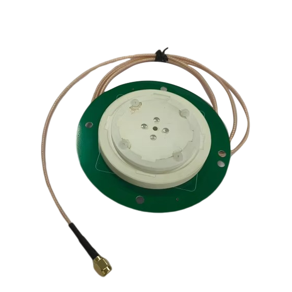
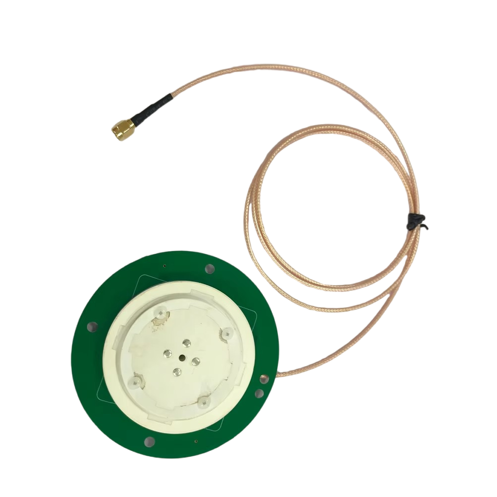
2.2.4 Housing and Enclosure
The housing protects the antenna’s internal components (radiating element, LNA, filter) from environmental damage. It is typically made of a high-performance plastic (e.g., polycarbonate, ABS) or composite material that is resistant to UV radiation, moisture, and temperature extremes. The housing must also be RF-transparent—meaning it does not block or attenuate GNSS signals. To achieve this, the material’s dielectric constant (εr) is carefully selected (typically between 2.0 and 3.0) to minimize signal loss. Additionally, the housing may include a gasket or seal to prevent water and dust ingress, meeting IP67 or IP6K9K standards (common in automotive applications).
2.2.5 Mounting Structure
The mounting structure determines how the antenna is attached to the vehicle. Common mounting locations include the roof (using a magnetic or adhesive mount), behind the windshield (integrated with the defroster grid), or in the rear spoiler. The mounting structure must be sturdy enough to withstand vibration (e.g., from rough roads) and wind loads (at high speeds) while ensuring that the antenna’s radiation pattern is not blocked by other vehicle components (e.g., metal roof rails, satellite radio antennas). For roof-mounted antennas, the mount may include a ground connection to the vehicle’s chassis, which helps reduce EMI and improve grounding for the antenna.
2.3 Construction Process
The construction of an automotive multi-band RTK antenna follows a rigorous process to ensure quality and consistency:
PCB Fabrication: The radiating element and ground plane are printed on a high-frequency PCB substrate (e.g., Rogers RO4350B, which has a low dielectric loss and stable performance across temperatures). The PCB is then cut to size using precision machining.
Component Assembly: The LNA, filter, and other electronic components (e.g., capacitors, resistors) are soldered to the PCB using surface-mount technology (SMT). This process requires high precision to avoid damaging the delicate components and ensure reliable electrical connections.
Testing and Calibration: After assembly, the antenna undergoes rigorous testing to verify its performance. Key tests include:
Gain and Radiation Pattern Testing: Conducted in an anechoic chamber to measure the antenna’s gain (typically 2–5 dBi for GNSS antennas) and radiation pattern (ensuring maximum gain toward the sky).
Noise Figure Testing: Measures the LNA’s noise figure to ensure it meets specifications.
Environmental Testing: Includes temperature cycling, humidity testing, vibration testing, and IP rating testing to verify durability.
Housing Integration: The tested PCB assembly is inserted into the housing, and the housing is sealed to prevent environmental ingress. The mounting structure is then attached to the housing, completing the antenna assembly.
In conclusion, the design and construction of an automotive multi-band RTK car antenna are a balance of performance, durability, and integration. Every component—from the radiating element to the housing—is optimized to meet the unique challenges of automotive environments while delivering the centimeter-level accuracy required for advanced automotive applications.
The automotive multi-band RTK car antenna solution operates on a combination of GNSS signal reception, multi-band processing, and real-time kinematic correction to deliver centimeter-level positioning accuracy. To fully grasp its functionality, it is essential to break down its working principles into three core stages: GNSS Signal Reception and Multi-Band Processing, RTK Correction Data Transmission, and Position Calculation with RTK Enhancement. Each stage builds on the previous one, addressing key limitations of standard GNSS systems and enabling high-precision positioning for vehicles.
3.1 Stage 1: GNSS Signal Reception and Multi-Band Processing
The first step in the antenna’s operation is capturing GNSS signals from multiple satellites and processing them across multiple frequency bands. Unlike single-band antennas, which only receive signals from one frequency (e.g., GPS L1), multi-band antennas are designed to receive signals from two or more bands (e.g., GPS L1/L2/L5, Galileo E1/E5a/E5b), allowing them to leverage the unique properties of each band to mitigate errors.
3.1.1 Signal Reception
GNSS satellites orbit the Earth at an altitude of ~20,000 km (for GPS and Galileo) and transmit continuous RF signals that carry two types of information: ephemeris data (detailed orbital parameters of the satellite, allowing the receiver to calculate the satellite’s position at any time) and pseudorange data (a measure of the time it takes for the signal to travel from the satellite to the antenna, used to estimate the distance between the satellite and the vehicle).
The multi-band antenna’s radiating element (typically a microstrip patch, as discussed in Section 2) is tuned to resonate at the frequencies of the target GNSS bands. When a GNSS signal reaches the antenna, the radiating element converts the RF signal into an electrical current, which is then passed to the low-noise amplifier (LNA). The LNA boosts the weak signal (which is often as low as -150 dBm) to a level that can be processed by the receiver, while the band-pass filter removes out-of-band interference (e.g., from cellular or Wi-Fi signals) that could corrupt the GNSS data.
3.1.2 Multi-Band Processing for Error Mitigation
The key advantage of multi-band processing lies in its ability to reduce two major sources of GNSS positioning error: ionospheric delay and multipath interference.
Ionospheric Delay Correction: The ionosphere is a layer of ionized particles in the upper atmosphere (80–600 km above Earth) that bends and delays GNSS signals. The amount of delay depends on the frequency of the signal—higher-frequency signals (e.g., GPS L5, 1.176 GHz) are less affected by the ionosphere than lower-frequency signals (e.g., GPS L1, 1.575 GHz). By receiving signals from two or more frequencies, the multi-band antenna (working with the RTK receiver) can calculate the difference in delay between the bands and use this information to model and cancel out the ionospheric delay. For example, the ionospheric delay for GPS L1 and L2 can be approximated using the Klobuchar model, but multi-band data allows for a more accurate, real-time correction. This is critical for high-precision positioning, as ionospheric delay can cause errors of up to 10 meters in single-band systems.
Multipath Interference Reduction: Multipath occurs when GNSS signals reflect off objects (e.g., buildings, trees, roads) before reaching the antenna. These reflected signals arrive at the antenna slightly later than the direct signal, leading to timing errors and positioning inaccuracies. Multi-band antennas mitigate multipath in two ways: first, their radiation pattern is optimized to receive direct signals from the sky while rejecting reflected signals (which often come from lower elevation angles); second, the receiver uses multi-band data to identify and discard multipath-contaminated signals. For example, if a signal from a satellite is received on both L1 and L2 bands, but the L1 signal shows signs of multipath (e.g., a sudden jump in pseudorange), the receiver can rely more on the L2 signal to calculate the position. This reduces multipath errors from several meters to centimeters.
3.2 Stage 2: RTK Correction Data Transmission
While multi-band processing reduces ionospheric and multipath errors, it does not eliminate all sources of GNSS inaccuracy—such as satellite clock errors, orbital errors (small deviations from the ephemeris data), and tropospheric delay (delay caused by water vapor and gases in the lower atmosphere). Real-Time Kinematic (RTK) technology addresses these errors by using a fixed reference station to generate correction data, which is then transmitted to the vehicle’s RTK receiver.
3.2.1 The Role of Reference Stations
An RTK reference station is a fixed location with a precisely known coordinate (surveyed to centimeter-level accuracy). The reference station is equipped with a high-precision GNSS receiver and antenna (often a multi-band RTK antenna similar to the one in the vehicle) that continuously tracks GNSS signals. By comparing its measured position (calculated from the GNSS signals) to its known true position, the reference station can compute the error vector—the difference between the measured and true position, which represents the combined effect of satellite clock errors, orbital errors, and tropospheric delay.
3.2.2 Correction Data Transmission and Reception
Once the reference station computes the error vector, it encodes this data into a standardized format—most commonly the RTKlib format (used in open-source systems) or proprietary formats from manufacturers like Trimble or Topcon—and transmits it to the vehicle’s RTK receiver. The transmission typically occurs via wireless communication technologies, with the choice of technology depending on factors like coverage, latency, and data rate:
Cellular Networks (4G LTE/5G): The most widely used option for automotive applications, as cellular networks offer extensive coverage (including urban, suburban, and rural areas) and low latency (typically <100 ms for 4G, <10 ms for 5G). This ensures that correction data reaches the vehicle in near real time, which is critical for dynamic automotive environments where the vehicle’s position is constantly changing.
Dedicated Short-Range Communication (DSRC): A short-range wireless technology (range ~300 meters) designed specifically for V2X communication. DSRC is ideal for urban areas where reference stations are densely deployed, as it enables direct, low-latency transmission of correction data between the reference station and the vehicle—without relying on cellular infrastructure.
Satellite Communication (Satcom): Used in remote areas where cellular or DSRC coverage is unavailable (e.g., rural highways, off-road environments). Satcom ensures that correction data is still transmitted to the vehicle, though it may have higher latency (100–500 ms) compared to cellular or DSRC.
The vehicle’s multi-band RTK antenna does not directly transmit or receive correction data (this is handled by the vehicle’s communication module), but it plays an indirect role: by providing accurate, real-time GNSS data to the RTK receiver, it ensures that the receiver can properly align and apply the correction data. For example, if the antenna’s GNSS data includes the time of signal reception, the receiver can synchronize this with the timestamp of the correction data to ensure the error correction is applied to the correct position measurement.
3.3 Stage 3: Position Calculation with RTK Enhancement
The final stage of the antenna’s operation involves the RTK receiver using the multi-band GNSS data and RTK correction data to compute the vehicle’s precise position. This process relies on two key techniques: carrier-phase measurements and integer ambiguity resolution—both of which are enabled by the multi-band antenna’s ability to capture high-quality GNSS signals.
3.3.1 Carrier-Phase Measurements
Standard GNSS receivers use pseudorange data (based on the time delay of the signal’s code component) to calculate position, which typically results in meter-level accuracy. RTK receivers, by contrast, use carrier-phase measurements—based on the phase of the GNSS signal’s carrier wave (e.g., 1.575 GHz for GPS L1)—which are far more precise. The carrier wave has a much shorter wavelength (e.g., ~19 cm for GPS L1) than the code component, so small changes in the phase can be measured to within a fraction of a wavelength (i.e., millimeters).
The multi-band antenna is critical for carrier-phase measurements because it captures signals from multiple bands, each with a unique carrier wavelength. For example, GPS L2 has a carrier wavelength of ~24 cm, while GPS L5 has a wavelength of ~25.4 cm. By comparing carrier-phase measurements across multiple bands, the receiver can reduce errors caused by cycle slips (temporary losses of the carrier-phase lock, often due to signal blockage or interference). If a cycle slip occurs on one band (e.g., L1), the receiver can use data from another band (e.g., L2) to correct it, ensuring continuous, precise measurements.
3.3.2 Integer Ambiguity Resolution
A key challenge with carrier-phase measurements is integer ambiguity—the unknown number of full carrier cycles between the satellite and the antenna. For example, if the distance between the satellite and the antenna is 20,000 km, the number of carrier cycles (for GPS L1) is ~105,263,158, but the receiver only measures the fractional part of the cycle (e.g., 0.3 cycles). Resolving this integer ambiguity is essential for centimeter-level accuracy.
Multi-band antennas simplify integer ambiguity resolution by providing measurements from multiple frequencies. The integer ambiguity for each band is related (since the distance between the satellite and the antenna is the same), so the receiver can use mathematical algorithms (e.g., the LAMBDA method) to solve for the unknown integers across all bands simultaneously. This is far more reliable than single-band systems, where ambiguity resolution often fails in challenging environments (e.g., urban canyons) due to weak or noisy signals.
Once the integer ambiguity is resolved, the receiver applies the RTK correction data to the carrier-phase measurements to eliminate errors from satellite clocks, orbits, and tropospheric delay. The result is a position calculation with centimeter-level accuracy (typically 1–5 cm horizontally, 2–10 cm vertically)—a transformative improvement over standard GNSS systems.
The automotive multi-band RTK car antenna solution offers a range of advantages that make it indispensable for next-generation automotive technologies, but it also faces significant challenges that must be addressed to accelerate adoption. Understanding these pros and cons is critical for manufacturers, engineers, and industry stakeholders looking to integrate this technology into vehicles.
4.1 Key Advantages
4.1.1 Unmatched Positioning Accuracy
The most significant advantage of multi-band RTK antennas is their ability to deliver centimeter-level positioning accuracy—a requirement for autonomous driving, precise V2X communication, and advanced fleet management. As discussed earlier, this accuracy is achieved through multi-band processing (which mitigates ionospheric and multipath errors) and RTK correction (which eliminates satellite and atmospheric errors). For example, in autonomous parking applications, centimeter-level accuracy ensures that the vehicle can align itself perfectly with a parking space, avoiding collisions with adjacent vehicles or curbs. In contrast, single-band GNSS antennas (with meter-level accuracy) would struggle to meet this requirement, leading to imprecise parking or safety risks.
4.1.2 Enhanced Reliability in Challenging Environments
Multi-band RTK antennas are far more reliable than single-band antennas in environments where satellite signals are weak, blocked, or interfered with. This includes:
Urban Canyons: Tall buildings block or reflect GNSS signals, causing multipath interference. Multi-band processing reduces multipath errors, while support for multiple GNSS constellations (e.g., GPS + Galileo + BeiDou) ensures that the antenna can capture signals from satellites that are visible above the buildings.
Rural and Remote Areas: In regions with limited satellite visibility (e.g., dense forests, mountain valleys), multi-band antennas leverage the redundancy of multiple constellations and bands to maintain positioning. For example, if GPS signals are blocked by a mountain, the antenna can switch to BeiDou or Galileo signals to continue operating.
Adverse Weather: Heavy rain, snow, or fog can attenuate GNSS signals, but multi-band antennas’ low-noise amplifiers (LNAs) and wideband filters ensure that weak signals are still captured and processed. This reliability is critical for safety-critical applications like ADAS, where signal loss could lead to accidents.
4.1.3 Compatibility with Evolving GNSS Ecosystems
As global GNSS constellations continue to expand and upgrade, multi-band RTK antennas are well-positioned to leverage these advancements. For example:
GPS III: The latest generation of GPS satellites includes the L1C band (designed for improved interoperability with other constellations) and enhanced signal strength, which multi-band antennas can support.
Galileo Second Generation (G2): Set to launch in the 2020s, G2 will add new bands (e.g., E6) for high-precision applications, which multi-band antennas can integrate with minimal hardware changes.
BeiDou-3: China’s latest GNSS constellation includes the B1C and B2a bands, which are compatible with GPS and Galileo, enabling multi-band antennas to achieve even greater redundancy and accuracy.
This compatibility ensures that multi-band RTK antennas will remain relevant for decades, as they can adapt to new constellations and bands without requiring a complete redesign.
4.1.4 Improved Integration with Vehicle Systems
Modern automotive multi-band RTK antennas are designed to integrate seamlessly with other vehicle systems, such as ADAS, V2X communication, and infotainment. For example:
ADAS Integration: The antenna’s precise position data is fed into ADAS algorithms to enable features like lane-keeping assist (LKA) and adaptive cruise control (ACC) with stop-and-go functionality. LKA, for instance, uses centimeter-level positioning to ensure the vehicle stays within its lane, even on roads with faded lane markers.
V2X Integration: Position data from the antenna is shared with other vehicles and infrastructure via V2X communication, enabling features like cooperative adaptive cruise control (CACC) and intersection collision warning. For CACC, vehicles use precise positioning to maintain a safe, consistent distance from the vehicle ahead, even at high speeds.
This integration reduces the need for redundant sensors, lowering the overall cost and complexity of vehicle systems.
4.2 Critical Challenges
4.2.1 High Cost of Components and Infrastructure
One of the biggest barriers to adoption is the high cost of multi-band RTK antennas and the supporting infrastructure. Multi-band antennas require specialized components—such as high-performance LNAs, wideband filters, and multi-resonant radiating elements—that are more expensive than those used in single-band antennas. For example, a multi-band RTK antenna can cost 2–5 times more than a single-band GPS antenna, which adds to the overall cost of the vehicle.
Additionally, RTK technology relies on a network of reference stations to generate correction data. Deploying and maintaining these stations (especially in rural areas) is costly—each reference station can cost tens of thousands of dollars to install, plus ongoing maintenance fees. While some regions (e.g., Europe, Japan) have government-funded RTK networks (e.g., Europe’s EGNOS, Japan’s MSAS), many areas lack this infrastructure, making it difficult for automakers to offer multi-band RTK solutions globally.
4.2.2 Vulnerability to Jamming and Spoofing
Like all GNSS-based systems, multi-band RTK antennas are vulnerable to jamming (intentional interference that blocks GNSS signals) and spoofing (sending fake GNSS signals to trick the receiver into calculating an incorrect position). Jamming devices—often small, low-cost devices that emit RF noise in GNSS frequency bands—can disrupt the antenna’s ability to capture signals, leading to loss of positioning. Spoofing is even more dangerous, as it can cause the vehicle to believe it is in a different location (e.g., on a highway instead of a city street), leading to accidents.
While multi-band antennas are more resistant to jamming than single-band antennas (since they can switch to an unjammed band), they are still vulnerable if all supported bands are jammed. Spoofing is also a growing concern, as spoofers can generate fake multi-band signals that are difficult for the receiver to distinguish from real ones. Addressing these vulnerabilities requires additional technologies—such as anti-jamming filters, signal authentication (e.g., GPS III’s Navigation Message Authentication), and sensor fusion (combining GNSS with lidar, radar, or inertial measurement units (IMUs))—which add cost and complexity.
4.2.3 Power Consumption and Thermal Management
Multi-band RTK antennas require more power than single-band antennas, as they must process signals from multiple bands and support the LNA and filter. This is a particular challenge for electric vehicles (EVs), where power efficiency is critical for maximizing range. For example, a multi-band RTK antenna may consume 50–100 mW of power, compared to 20–30 mW for a single-band antenna. While this may seem small, every milliwatt counts in EVs, where even minor increases in power consumption can reduce range by several kilometers over a long drive.
Additionally, the LNA and other electronic components generate heat during operation, which can degrade performance if not managed properly. In automotive environments—where temperatures can reach 85°C—thermal management is critical. Multi-band antennas require heat sinks or thermal pads to dissipate heat, which increases their size and weight. This can make integration into compact vehicle designs (e.g., small EVs) challenging.
4.2.4 Regulatory and Standardization Issues
The global adoption of multi-band RTK antennas is hindered by regulatory and standardization challenges. Different regions have different regulations governing GNSS frequency bands—for example, some bands used by Galileo or BeiDou are not yet approved for use in certain countries (e.g., parts of the Middle East or Africa). This requires automakers to design region-specific antennas, increasing development costs.
Additionally, there is a lack of global standards for RTK correction data formats and transmission protocols. While some standards (e.g., RTKlib) exist, many manufacturers use proprietary formats, which makes it difficult for different systems (e.g., a vehicle using a Trimble receiver and a reference station using a Topcon system) to communicate. This fragmentation slows down the deployment of RTK networks and limits the interoperability of multi-band RTK solutions.
The automotive multi-band RTK car antenna solution is already transforming a range of automotive applications, from autonomous driving to fleet management. As technology advances and challenges are addressed, its applications will expand further, while new trends will shape its evolution. This section explores the current key applications and future trends of this critical technology.
5.1 Key Current Applications
5.1.1 Autonomous Driving (AD)
Autonomous driving is the most high-profile application of multi-band RTK antennas, as centimeter-level positioning is essential for all levels of autonomy (L3 to L5). For example:
L3 Autonomy (Conditional Automation): Vehicles with L3 autonomy can handle most driving tasks (e.g., highway driving) but require the driver to take over in certain situations. Multi-band RTK antennas provide the precise positioning needed to maintain lane position, navigate highway exits, and avoid obstacles. For instance, Tesla’s Autopilot (which is approaching L3 capability) uses multi-band GNSS (including GPS L1/L2 and Galileo E1/E5a) to enhance positioning accuracy.
L4/L5 Autonomy (High/Full Automation): L4 and L5 vehicles require no human intervention, even in complex urban environments. Multi-band RTK antennas are critical here, as they enable the vehicle to navigate narrow streets, avoid pedestrians and cyclists, and park autonomously. For example, Waymo’s self-driving taxis use multi-band RTK antennas (paired with lidar and radar) to achieve centimeter-level positioning in cities like Phoenix and San Francisco.
Without multi-band RTK antennas, autonomous vehicles would rely solely on lidar and radar, which are more expensive and have shorter ranges. The antenna’s ability to provide long-range, precise positioning reduces the reliance on other sensors, lowering costs and improving reliability.
5.1.2 Advanced Driver Assistance Systems (ADAS)
While ADAS systems (e.g., L1/L2 autonomy) do not require centimeter-level accuracy, multi-band RTK antennas still enhance their performance. Key ADAS applications include:
Lane-Keeping Assist (LKA): LKA uses positioning data to ensure the vehicle stays within its lane. Multi-band RTK antennas provide the precision needed to detect small lane departures (e.g., 10–20 cm) and correct them, even when lane markers are faded or missing.
Adaptive Cruise Control with Stop-and-Go (ACC-SG): ACC-SG maintains a safe distance from the vehicle ahead. Multi-band RTK antennas enable the system to predict the leading vehicle’s position more accurately, reducing braking and acceleration events and improving passenger comfort.
Automatic Emergency Braking (AEB): AEB uses positioning data to detect potential collisions with other vehicles or pedestrians. Multi-band RTK antennas provide faster, more accurate position updates, allowing the system to trigger braking earlier and avoid accidents.
According to a study by the Insurance Institute for Highway Safety (IIHS), ADAS systems enhanced with multi-band RTK reduce rear-end collisions by 30–40% compared to systems using single-band GNSS.
5.1.3 Vehicle-to-Everything (V2X) Communication
V2X communication enables vehicles to exchange data with other vehicles (V2V), infrastructure (V2I), pedestrians (V2P), and the cloud (V2C). Precise positioning is essential for V2X, as it ensures that vehicles can accurately report their location and interpret the location of other objects. Multi-band RTK antennas support key V2X applications:
Cooperative Adaptive Cruise Control (CACC): CACC allows a platoon of vehicles to travel closely together (with gaps of 1–2 seconds) by sharing position and speed data. Multi-band RTK antennas ensure that each vehicle in the platoon knows the exact position of the vehicle ahead, reducing fuel consumption and improving traffic flow.
Intersection Collision Warning (ICW): ICW uses V2I communication to alert drivers of potential collisions at intersections. The antenna’s precise positioning ensures that the system can accurately determine the vehicle’s distance from the intersection and the speed of oncoming vehicles, triggering warnings in time to avoid accidents.
Pedestrian Safety: V2P communication alerts drivers of pedestrians in the vicinity. Multi-band RTK antennas (paired with pedestrian smartphones or wearables that use GNSS) provide the precise position of pedestrians, even in crowded urban areas.
5.1.4 Fleet Management and Logistics
Fleet operators rely on multi-band RTK antennas to optimize operations, improve safety, and reduce costs. Key applications include:
Precise Tracking: Multi-band RTK antennas enable real-time tracking of fleet vehicles with centimeter-level accuracy. This allows operatorsto monitor the exact location of each vehicle, ensuring compliance with delivery schedules and identifying any unauthorized detours. For example, a logistics company delivering time-sensitive medical supplies can use the antenna’s data to track the vehicle’s progress in real time and adjust routes if delays occur, ensuring the supplies arrive on time.
Route Optimization: By combining precise positioning data with traffic information, fleet management systems can optimize routes to reduce fuel consumption (or EV battery usage) and travel time. For instance, if the antenna detects that a vehicle is approaching a traffic jam, the system can reroute it to a less congested road, saving time and reducing operational costs.
Driver Safety Monitoring: Multi-band RTK antennas can be paired with telematics systems to monitor driver behavior, such as harsh braking, speeding, or sudden lane changes. The precise positioning data allows the system to detect these behaviors accurately, enabling fleet operators to provide targeted training to improve driver safety and reduce the risk of accidents.
5.2 Future Trends
5.2.1 Integration with 6G and Advanced Communication Technologies
As 6G networks begin to roll out in the 2030s, multi-band RTK antennas will integrate with this technology to further enhance positioning accuracy and reliability. 6G will offer ultra-low latency (less than 1 ms) and high data rates, which will enable real-time transmission of large volumes of RTK correction data. This will be particularly beneficial for autonomous driving, as it will allow vehicles to receive correction data faster, reducing the time between position updates and improving the vehicle’s ability to react to dynamic road conditions.
Additionally, 6G will support terrestrial-satellite integration, which will extend the coverage of RTK networks to remote areas (e.g., deserts, oceans) where cellular or DSRC coverage is currently unavailable. This will enable multi-band RTK antennas to be used in off-road vehicles, shipping vessels, and aerial drones, expanding their applications beyond traditional automotive use cases.
5.2.2 Miniaturization and Cost Reduction
One of the key trends in the development of multi-band RTK antennas is miniaturization. As semiconductor technology advances, manufacturers will be able to reduce the size of the antenna’s components (e.g., LNAs, filters, radiating elements) while maintaining or improving performance. This will allow the antenna to be integrated into smaller vehicle designs (e.g., micro-EVs, urban mobility vehicles) and even into other devices (e.g., smartphones, wearables) for pedestrian positioning.
Along with miniaturization, cost reduction will be a major focus. As production volumes increase and component costs decrease, the price of multi-band RTK antennas is expected to drop by 30–50% over the next decade. This will make the technology more accessible to mid-range and entry-level vehicles, accelerating its adoption in the mass market. For example, by 2030, multi-band RTK antennas could become a standard feature in most new vehicles, similar to how GPS antennas are standard today.
5.2.3 Sensor Fusion with AI and Machine Learning
To address the vulnerabilities of GNSS-based systems (e.g., jamming, spoofing), multi-band RTK antennas will increasingly be integrated with other sensors (e.g., lidar, radar, IMUs) through sensor fusion technologies. Sensor fusion combines data from multiple sensors to provide a more accurate and reliable position estimate than any single sensor alone. For example, if a multi-band RTK antenna is jammed, the vehicle can rely on lidar and radar data to maintain positioning until the jam is resolved.
Artificial intelligence (AI) and machine learning (ML) will play a key role in sensor fusion. AI/ML algorithms will be used to analyze data from the antenna and other sensors in real time, identifying patterns and anomalies that indicate jamming or spoofing. For example, an ML algorithm could detect a sudden, unexplained change in the antenna’s position data (a sign of spoofing) and switch to lidar/radar data automatically. This will improve the robustness and security of multi-band RTK systems, making them more suitable for safety-critical applications like autonomous driving.
5.2.4 Expansion into Smart City and Smart Mobility Ecosystems
Multi-band RTK antennas will become a core component of smart city and smart mobility ecosystems. In smart cities, the antenna’s precise positioning data will be used to optimize traffic flow, manage parking spaces, and monitor public transportation. For example, a smart city could use data from multi-band RTK antennas in vehicles and infrastructure to adjust traffic light timings based on real-time traffic conditions, reducing congestion and improving air quality.
In smart mobility ecosystems, multi-band RTK antennas will enable seamless integration between different modes of transportation (e.g., cars, buses, trains, bicycles). For example, a commuter could use a smartphone equipped with a multi-band RTK antenna to navigate from their home to a train station, then from the train station to their workplace using a shared electric vehicle—all with centimeter-level accuracy. This will improve the efficiency and convenience of multi-modal transportation, encouraging more people to use sustainable mobility options.
Conclusion
The automotive multi-band RTK car antenna solution represents a transformative technology in the automotive industry, enabling centimeter-level positioning accuracy that is essential for the development of autonomous driving, advanced ADAS, V2X communication, and smart fleet management. Throughout this analysis, we have explored the solution’s overview, design and construction, working principles, advantages and challenges, and current applications and future trends—highlighting its critical role in shaping the future of mobility.
From an overview perspective, the multi-band RTK antenna addresses the limitations of single-band GNSS systems by leveraging multiple frequency bands and RTK correction data to mitigate errors from ionospheric delay, multipath interference, and satellite clock/orbital inaccuracies. Its design and construction are engineered to meet the stringent requirements of automotive environments, with components like microstrip patch radiating elements, low-noise amplifiers, and robust housings ensuring performance, durability, and integration with vehicle systems.
The working principles of the antenna—from GNSS signal reception and multi-band processing to RTK correction data transmission and position calculation—demonstrate how it achieves centimeter-level accuracy through carrier-phase measurements and integer ambiguity resolution. Its advantages, including unmatched accuracy, enhanced reliability in challenging environments, compatibility with evolving GNSS ecosystems, and seamless integration with vehicle systems, make it indispensable for next-generation automotive technologies. However, challenges like high cost, vulnerability to jamming/spoofing, power consumption, and regulatory issues must be addressed to accelerate its adoption.
Looking at current applications, the antenna is already transforming autonomous driving, ADAS, V2X communication, and fleet management—improving safety, efficiency, and convenience for drivers, fleet operators, and pedestrians. Future trends, such as integration with 6G, miniaturization and cost reduction, sensor fusion with AI/ML, and expansion into smart city ecosystems, will further expand its applications and solidify its position as a key enabler of smart mobility.
In conclusion, the automotive multi-band RTK car antenna solution is not just a technological innovation—it is a catalyst for the transition to a safer, more efficient, and more connected transportation system. As the automotive industry continues to evolve, the multi-band RTK antenna will play an increasingly important role in realizing the vision of autonomous driving, smart cities, and sustainable mobility. With ongoing advancements in technology and a focus on addressing key challenges, the future of multi-band RTK antennas is bright, and their impact on the automotive industry and society as a whole will be profound.

 86 0755 2819 9597
Lucy Yang | lucy.y@toxutech.com
Nicole Li | nicole@toxutech.com
Dotty Zhao | sales04@toxutech.com
Global Business Director / Sales Team / Global Operations


 En
En Cn
Cn Korean
 Home >


