

-
Products -PCBA Manufacturing RF Connectors RF Cable Assemblys Embedded Antennas External Antennas Positioning Chips and Modules
RF Connectors

RF Cable Assemblys
Embedded Antennas
External Antennas
Positioning Chips and Modules


 Language


Language


The modern automobile has evolved into a sophisticated connected platform, and at the core of this transformation lies the Global Navigation Satellite System (GNSS) antenna. Far from a simple accessory, the automotive GNSS antenna is a critical component that enables a vast array of functionalities, from basic turn-by-turn navigation and emergency calling to advanced driver-assistance systems (ADAS), vehicle tracking, and usage-based insurance. The automotive environment presents a unique set of extreme challenges—thermal, mechanical, and electromagnetic—that demand a specialized antenna solution. The ubiquitous FAKRA connector is the industry-standard interface that ensures reliable and standardized integration of this vital component into the vehicle's architecture.
An automotive GNSS antenna is a specialized active antenna system designed for one primary purpose: to provide a robust and continuous positioning signal to the vehicle's telematics unit or infotainment system, regardless of driving conditions. Unlike consumer-grade antennas, it must perform flawlessly across a temperature range of -40°C to +85°C (and up to 105°C in some engine bay applications), withstand intense UV exposure, vibration, shock, and exposure to chemicals like salt spray. Furthermore, it must operate in an increasingly hostile Radio Frequency (RF) environment, crowded with emissions from the vehicle's own systems (e.g., CAN bus, radars, other antennas) and external sources.
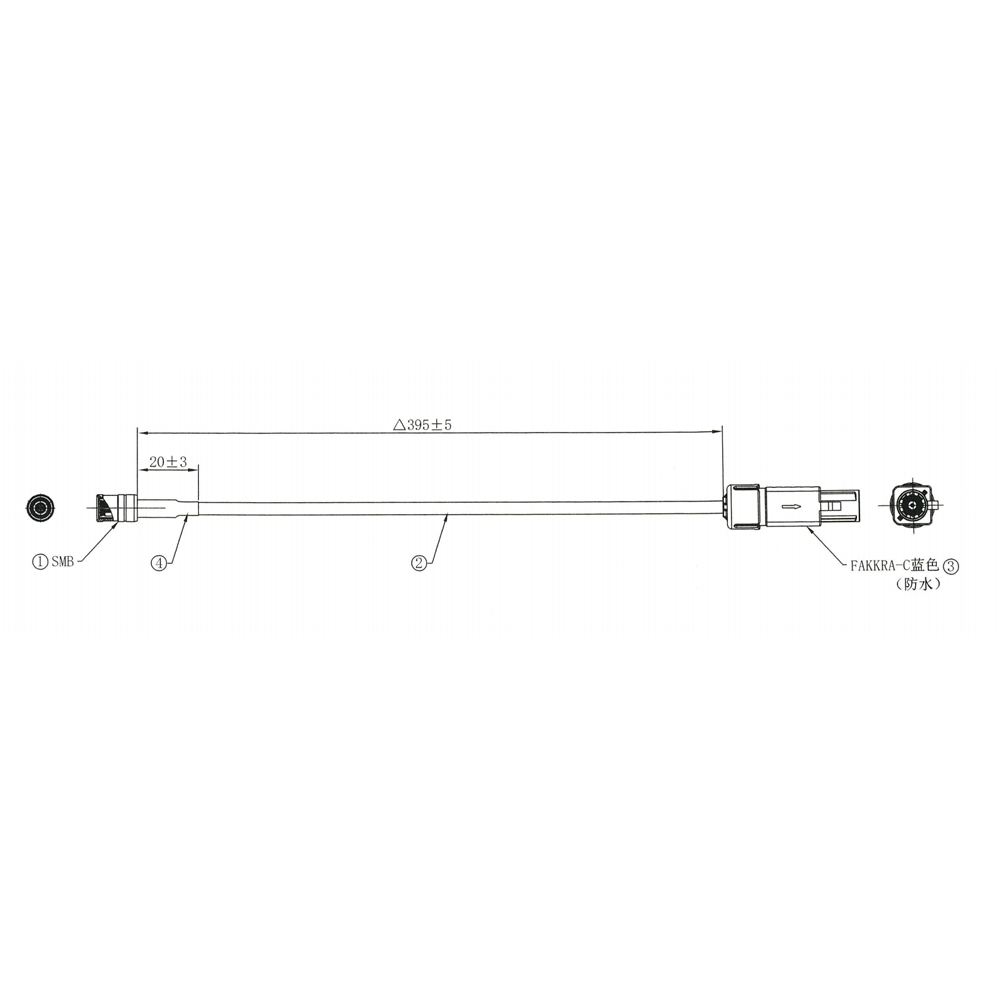
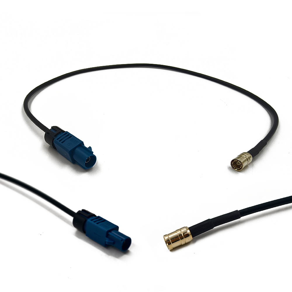
The FAKRA connector (a German abbreviation for Fachkreis Automobil, or "Automobile Expert Group") is as important as the antenna itself. Developed in the early 2000s, this standardized coaxial connector system solved a critical problem for the automotive industry: ensuring consistent, reliable, and keyed RF connections in a high-volume manufacturing environment. FAKRA connectors are color-coded and mechanically keyed to prevent mis-mating during assembly line installation. The most common color for GNSS systems is blue, which designates a 50-ohm impedance connector for radio services (GPS/GNSS falls under this category). This standardization allows automakers to source antennas and wiring harnesses from multiple suppliers with the confidence that they will interconnect seamlessly.
The typical placement for these antennas is on the vehicle's roof, often integrated into the shark-fin or fin-type antenna module. This location is ideal for several reasons: it provides a mostly unobstructed 360-degree view of the sky, is typically the highest point on the vehicle for best satellite visibility, and allows for a large, solid ground plane (the vehicle's roof sheet metal) which is essential for optimal antenna performance. However, antennas are also found in other locations, such as embedded in the dashboard, rear window, or even the front bumper, each presenting its own unique performance challenges that the antenna design must overcome.
A modern automotive GNSS antenna is rarely a single-band GPS receiver. It is a multi-GNSS antenna, capable of receiving signals from all major constellations (GPS, GLONASS, Galileo, BeiDou) to ensure global coverage and improve accuracy by leveraging more satellites. It is almost always an active antenna, meaning it incorporates a Low-Noise Amplifier (LNA) to compensate for cable loss and boost the extremely weak satellite signals before they are degraded by the long cable run to the telematics unit.
In summary, the automotive GNSS antenna with its FAKRA connector is a masterpiece of reliability engineering. It represents a perfect synergy of RF performance, environmental ruggedness, and manufacturing standardization. It is the unsung hero that provides the fundamental data stream of location, enabling the connected, navigated, and increasingly autonomous driving experiences that define the modern automotive era.
The design and construction of an automotive GNSS antenna with a FAKRA connector is a rigorous process governed by stringent automotive-grade standards, balancing electromagnetic performance with unparalleled durability and cost-effective high-volume manufacturing.
The Radiating Element: Ceramic Patch Foundation
The core of the antenna is almost invariably a ceramic patch antenna. The substrate is a high-dielectric-constant ceramic material (εr typically between 20 and 40), chosen to achieve a small form factor that can fit within the constrained space of a shark-fin housing. Common materials include alumina or barium-strontium-titanate blends. The patch itself, typically made of silver or copper, is printed onto the ceramic with precise geometry to resonate at the target GNSS frequencies (e.g., 1575.42 MHz for L1). For multi-GNSS support covering a wider frequency range (e.g., from 1550 MHz to 1610 MHz), the patch design incorporates techniques like slot-cutting or utilizes a stacked-patch configuration to broaden the bandwidth.
The Ground Plane: The Vehicle's Roof
A critical design aspect often overlooked is that the vehicle's roof itself acts as the antenna's ground plane. The performance of a patch antenna is heavily dependent on the size and electrical characteristics of the ground plane beneath it. Automotive antenna designers must work with a finite ground plane size defined by the roof's dimensions and curvature. The antenna is designed and simulated to perform optimally with this specific ground plane in mind. The use of the vehicle's body is a key advantage, providing a large, solid metallic surface that enhances gain and helps shape the radiation pattern for a hemispherical coverage towards the sky.
The Active Component: Automotive-Grade LNA
Given the long cable runs (often 4-6 meters) from the roof to the telematics unit in the dashboard, signal loss in the coaxial cable is significant. Therefore, every automotive GNSS antenna is an active antenna, integrating a Low-Noise Amplifier (LNA) directly at the feed point. This LNA is not a commercial-off-the-shelf component; it is an automotive-grade semiconductor chosen for its ability to operate reliably across the extreme temperature range and its resistance to thermal shock. Key specifications include:
Low Noise Figure (NF): Typically < 1.5 dB to avoid degrading the already-weak satellite signals.
Gain: Typically between 25-30 dB to overcome the subsequent cable loss.
High Linearity (IP3): Essential to avoid compression or intermodulation from strong in-vehicle transmitters (e.g., cellular modems also located in the shark-fin).
Shielding and Filtering: Surviving the RF Jungle
The automotive EM environment is brutal. The antenna and its LNA are housed in a sealed metalized plastic cavity or within a dedicated shielding can. This protects them from external interference. Furthermore, advanced Bulk Acoustic Wave (BAW) or Surface Acoustic Wave (SAW) filters are integrated into the RF path. These are highly selective band-pass filters that reject powerful out-of-band interference from cellular services (4G/5G), Bluetooth, Wi-Fi, and vehicle radars, preventing the LNA from being overloaded.
The FAKRA Connector: Standardized Interface
The FAKRA connector is crimped or soldered to the end of the coaxial cable. The connector housing is made from high-temperature resistant plastic (often PBT). Its keyed and colored design (blue for GPS/GNSS) ensures foolproof mating on the assembly line. The connector also provides the DC power for the integrated LNA from the telematics unit via the same coaxial cable, typically using a 3V or 5V bias.
Housing and Environmental Sealing
The entire assembly is housed within a protective outer shell. For roof-mounted modules, this is the iconic "shark-fin," made from materials like Polycarbonate (PC) or Polypropylene (PP) blended with UV stabilizers to prevent fading and cracking from sun exposure. The assembly is hermetically sealed, often using laser welding or ultrasonic welding of the housing parts along with silicone gaskets, to achieve an IP6K9K rating (protection against powerful water jets and dust ingress). This sealing is critical to prevent moisture condensation, which would severely degrade performance and lead to failure.
Validation and Testing
The design process is validated through extensive 3D electromagnetic simulation (e.g., CST, HFSS) to model performance on the specific car roof. Prototypes undergo a brutal battery of tests defined by automotive standards (e.g., ISO 16750), including thermal cycling, vibration, mechanical shock, humidity, salt spray, and RF performance validation in anechoic chambers. This ensures the antenna will perform for the lifetime of the vehicle.
The working principle of an automotive GNSS antenna system is a continuous battle against signal loss, environmental degradation, and electromagnetic interference, all to deliver a clean, amplified signal to the receiver that is usable for accurate positioning.
The Signal Chain: From Space to the Receiver
Signal Capture: The ceramic patch element acts as a transducer, converting the electromagnetic waves from GNSS satellites (which arrive with a power level as low as -130 dBm) into a tiny electrical current on its feed point.
Pre-Amplification (The Critical Step): This faint electrical signal is immediately fed into the integrated LNA. The LNA's primary role is to amplify the signal before any significant loss occurs. Its low noise figure ensures it adds minimal inherent noise during this process. This step is crucial because the subsequent coaxial cable run to the telematics unit has significant attenuation (loss can be 2-4 dB per meter). Without pre-amplification, the signal would be attenuated below the noise floor of the receiver, making it irretrievable.
Filtering: The amplified signal then passes through a band-pass filter. This filter performs the essential task of "cleaning" the signal by rejecting powerful out-of-band interference. In a vehicle, strong signals from cellular transceivers (which can be +23 dBm or higher) are the biggest threat. If these signals entered the LNA, they could cause compression (blocking) or generate intermodulation products that would drown out the weak GNSS signals. The filter ensures only the GNSS frequency band (~1550-1610 MHz) passes through.
Transmission: The now-cleaned and amplified signal is transmitted down the coaxial cable. The FAKRA connector at the end of this cable ensures a reliable, 50-ohm impedance-matched connection to the telematics unit, minimizing signal reflections at the interface.
Receiver Processing: The telematics unit provides the DC bias voltage to power the antenna's LNA through the same coaxial cable (via a bias-T circuit). It then receives the RF signal, down-converts it, and the internal GNSS receiver chip performs the complex digital signal processing (correlation, demodulation) to calculate the vehicle's position, velocity, and time (PVT).
Maintaining Signal Integrity in a Dynamic Environment
The antenna must perform consistently while the vehicle is in motion through constantly changing environments. This involves:
Multipath Mitigation: In urban canyons, signals reflect off buildings, creating multipath. The antenna's radiation pattern is designed to have higher gain towards the zenith (where direct signals come from) and lower gain towards the horizon (where multipath often originates). Furthermore, the circular polarization (RHCP) of the antenna helps reject reflected signals that have become partially LHCP.
Continuous Operation: Unlike a consumer device, the automotive antenna is always on when the vehicle is running, providing a continuous location data stream not just for navigation, but for a multitude of vehicle systems.
The Role of the FAKRA Interface
The FAKRA connector is not a passive component in this process. It ensures:
Impedance Matching: A consistent 50-ohm connection is maintained throughout the signal chain, preventing standing waves and signal loss due to reflections.
Shielding: The connector body and its interface provide continuous shielding, preventing external EMI from coupling into the cable and corrupting the weak GNSS signal.
Reliable Power Delivery: The robust mechanical connection ensures uninterrupted delivery of DC power to the remote LNA.
In essence, the antenna system works as a signal recovery and preservation unit. It captures a whisper of a signal from space, protects and amplifies it in a hostile environment, and delivers it reliably over a long distance to the brain of the vehicle's navigation system.
The standardized design of automotive GNSS antennas with FAKRA connectors offers significant systemic advantages for manufacturers and consumers alike, but the extreme operating environment presents a persistent set of engineering challenges.
Advantages:
Standardization and Interchangeability (The FAKRA Advantage): This is the single greatest benefit. The color-coded and keyed FAKRA system allows different Tier 1 and Tier 2 suppliers to provide interoperable components. An automaker can source antennas from one vendor and wiring harnesses from another, with the confidence they will connect correctly on the assembly line, simplifying logistics and reducing cost.
Proven Reliability and Durability: Automotive-grade components are designed and tested to survive a 15-20 year lifespan under extreme conditions. The rigorous validation against standards like ISO 16750 ensures that the antenna will withstand temperature cycles, vibration, moisture, and UV exposure that would quickly destroy a consumer-grade antenna.
Optimized Performance: The integrated active design (LNA) is perfectly tailored to the application. The gain of the LNA is chosen to precisely offset the known loss of the standard cable run, ensuring the receiver gets a signal with an optimal signal-to-noise ratio (SNR). The use of the vehicle's roof as a ground plane provides a stable and effective RF platform.
Simplified Assembly and Service: The foolproof nature of the FAKRA connector enables faster, error-proof installation on the high-speed automotive assembly line. It also simplifies aftermarket repairs and replacements for service technicians.
Integrated Design (Shark-Fin): The shark-fin housing allows for the aesthetically pleasing integration of multiple antennas (GNSS, cellular, satellite radio, TV) into a single, aerodynamic module, reducing drag and improving vehicle design.
Challenges and Limitations:
The Hostile RF Environment: This is the paramount challenge. The co-location of multiple wireless services (4G/5G, V2X, Wi-Fi, Bluetooth, radars) in close proximity creates a intense RF environment. Preventing these powerful transmitters from desensitizing the hypersensitive GNSS receiver requires complex and expensive filtering and shielding strategies, adding cost and design complexity.
Non-Ideal Placements and Compromises: While the roof is ideal, packaging constraints sometimes force antenna placements into sub-optimal locations like dashes, bumpers, or rear windows. These locations can have obstructed views of the sky, smaller ground planes, and increased exposure to multipath and interference, necessitating performance compromises.
Thermal Management: The integrated LNA generates heat during operation. When sealed inside a black shark-fin module sitting on a hot roof in direct summer sun, junction temperatures can soar, threatening the semiconductor's longevity and potentially causing performance drift. Managing this heat is a constant challenge.
Cost Pressure: The automotive industry is fiercely cost-competitive. Every component, including advanced BAW filters and automotive-grade LNAs, is subject to extreme cost-down pressure. This can limit the adoption of the most advanced performance-enhancing technologies until they become cost-effective.
Increasing Bandwidth Requirements: As GNSS evolves to include more constellations and more frequency bands (L1, L2, L5), the antenna must maintain performance across a wider bandwidth. Designing a small, cost-effective patch antenna that performs well from 1176 MHz (L5) to 1602 MHz (GLONASS) is a significant technical hurdle.
Testing and Validation Complexity: Ensuring reliability and performance across all vehicle models and environmental conditions requires an enormous investment in testing time and sophisticated anechoic chamber facilities, adding to the development cost and time.
The automotive GNSS antenna is the linchpin for a rapidly expanding ecosystem of connected vehicle services and advanced automotive technologies, its role evolving far beyond simple navigation.
Applications:
Telematics and Emergency Services: The core application. Enacles vehicle tracking, stolen vehicle recovery, remote diagnostics, and automatic collision notification and emergency response (e.g., GM's OnStar, BMW Assist). The GNSS antenna provides the crucial location data in these life-saving and security applications.
Advanced Driver-Assistance Systems (ADAS): High-quality location data is a key sensor input for ADAS. It provides context for other sensors (cameras, radar, lidar), enabling features like intelligent speed adaptation, predictive headlight control, and navigation-based cruise control that anticipates curves and hills.
Connected Navigation and Traffic Services: Powers real-time traffic updates, predictive routing, and cloud-based navigation platforms that offer points-of-interest search and over-the-air map updates. The antenna ensures continuous positioning even in urban areas.
Usage-Based Insurance (UBI) and Fleet Management: Provides the precise driving data (location, speed, mileage, time of day) required for insurance risk assessment and for managing logistics and driver behavior for commercial fleets.
Autonomous Vehicle Development: While full autonomy (L4/L5) will rely on sensor fusion, GNSS provides the essential absolute positioning and lane-level accuracy required for localizing the vehicle on a high-definition map, which is a foundational technology for current autonomous driving systems.
V2X Communication (Future): For Vehicle-to-Everything communication to function, especially for safety-of-life applications like intersection movement assist, each vehicle must know its own position with high accuracy and integrity. The GNSS antenna is the primary source for this data.
Future Trends:
Multi-Band GNSS for Enhanced Accuracy: The future is the widespread adoption of dual-frequency (L1 + L5) GNSS in automotive. L5 signals are stronger, have higher bandwidth, and are less affected by ionospheric delay. This will enable lane-level accuracy (20-30 cm) without solely relying on correction services, which is critical for ADAS and V2X applications.
Dead Reckoning Integration (GNSS/INS): Tightly coupling the GNSS receiver with an Inertial Navigation System (INS) containing accelerometers and gyroscopes will become standard. This allows the vehicle to maintain a highly accurate position solution during short GNSS outages in tunnels, parking garages, and urban canyons, providing continuous and seamless positioning.
Integrated Active Antenna Systems (AAS): The shark-fin will evolve into a sophisticated "Active Antenna System" where the antenna elements are integrated with beamforming capabilities and amplifiers, connected via a standardized FAKRA-over-Coax or 以太网 interface, allowing for more advanced signal processing and control.
Enhanced Interference Mitigation: With the RF environment becoming more crowded, antennas and receivers will incorporate more advanced anti-jamming and anti-spoofing techniques, such as adaptive filtering and null-steering, to ensure operational safety and security against intentional and unintentional interference.
Standardization towards H-MTD and AEF: The industry is moving towards new connector standards like H-MTD (High-Speed FAKRA) and AEF (Automotive Ethernet FaKra) to support higher data rates required for connected antenna modules and to reduce wiring harness complexity. These will coexist with and eventually supplant traditional FAKRA for advanced applications.
Material Science Innovations: Development of new ceramic substrates with lower loss tangents and more stable dielectric constants over temperature will enable smaller, more efficient, and more stable antennas to meet the demands of future multi-band, multi-function modules.
Conclusion
The automotive GNSS antenna with its FAKRA connector is a paradigm of successful engineering standardization and ruggedization. It exemplifies how a component can be transformed from a generic electronic part into a specialized, automotive-grade appliance designed for a lifetime of reliable service under the most demanding conditions. Its evolution has been driven by the dual engines of relentless automotive cost pressure and the exponentially increasing performance demands of connected and automated vehicle technologies.
The humble FAKRA connector has been instrumental in this journey, providing the reliable, standardized, and foolproof interface that enabled the high-volume integration of RF technology into the automobile. While new standards are on the horizon, FAKRA's legacy of reliability and interoperability is undeniable.
The role of the GNSS antenna has expanded from a simple navigation aid to a critical safety and connectivity sensor. It is now an indispensable source of truth for the vehicle's location, enabling everything from emergency response to the first steps towards autonomy. The future trends of multi-band reception, sensor fusion, and advanced interference mitigation will only deepen this criticality, pushing the performance boundaries of these antennas further.
In conclusion, the automotive GNSS antenna is far more than a "GPS antenna." It is a highly engineered, robust, and intelligent system that serves as the fundamental gateway between the vehicle and its geographic context. It is a key enabler of the modern connected driving experience and will remain a cornerstone of automotive electronics architecture as the industry continues its march towards higher levels of automation and connectivity.

 86 0755 2819 9597
Lucy Yang | lucy.y@toxutech.com
Nicole Li | nicole@toxutech.com
Dotty Zhao | sales04@toxutech.com
Global Business Director / Sales Team / Global Operations


 En
En Cn
Cn Korean
 Home >


