

-
Products -PCBA Manufacturing RF Connectors RF Cable Assemblys Embedded Antennas External Antennas Positioning Chips and Modules
RF Connectors

RF Cable Assemblys
Embedded Antennas
External Antennas
Positioning Chips and Modules


 Language


Language


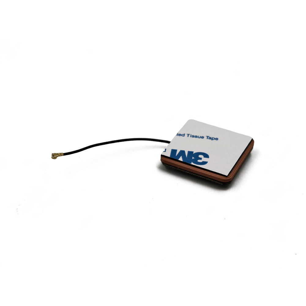
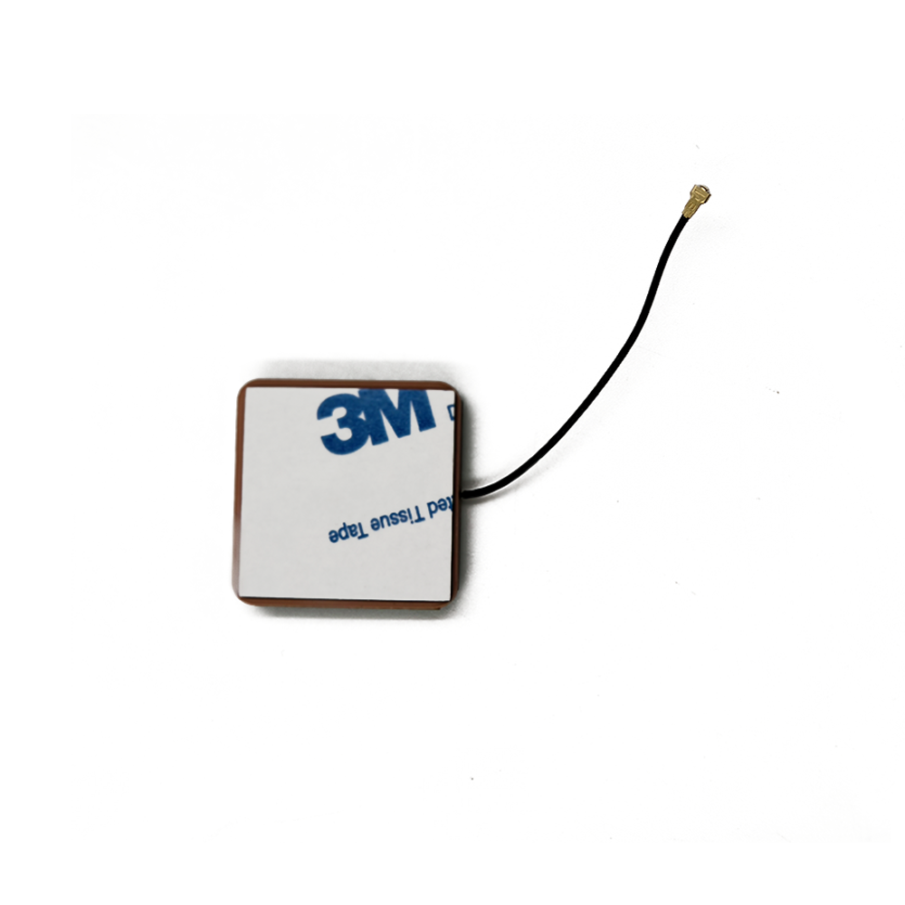

In the realm of wireless communication and positioning, the demand for antennas that combine compact size, reliable signal performance, and resistance to harsh environmental conditions has grown exponentially. The active ceramic patch antenna with waterproof housing emerges as a specialized solution that addresses these needs, integrating the advantages of active ceramic patch technology with robust waterproofing to operate seamlessly in wet, dusty, or rugged environments. Unlike standard active ceramic patch antennas— which are vulnerable to moisture damage and limited to indoor or sheltered use—this variant is engineered to withstand exposure to rain, splashes, submersion, and humidity, making it indispensable for applications ranging from outdoor IoT sensors to marine navigation systems.
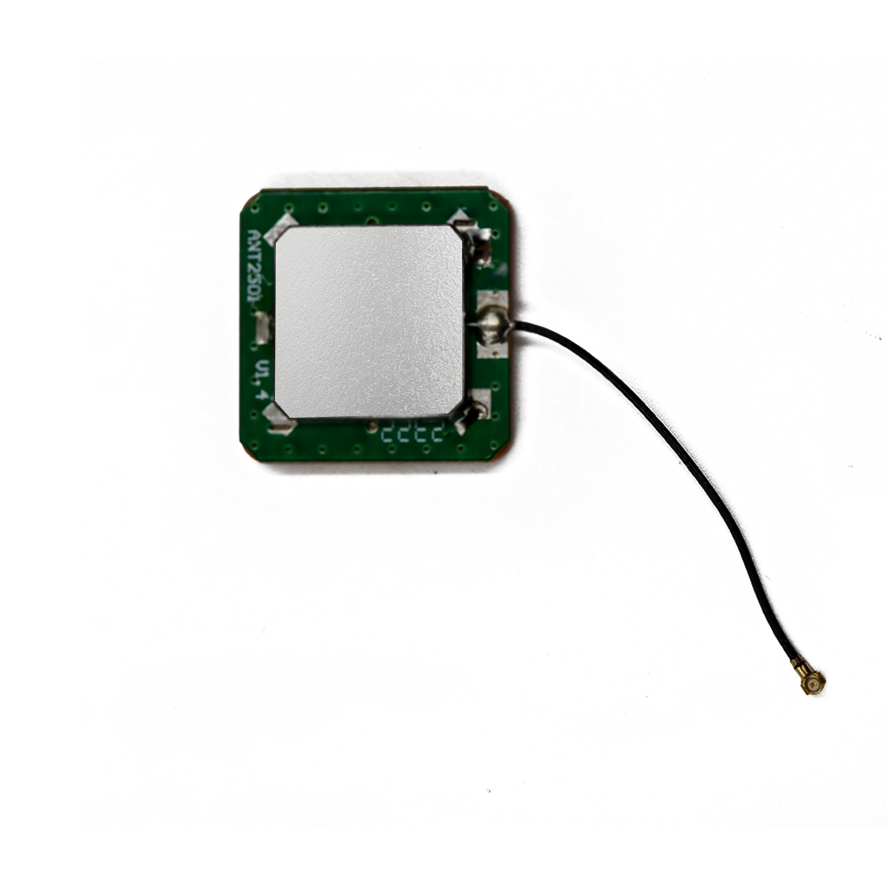
To grasp its significance, it is first essential to break down the core components and purpose of this antenna. At its base, an active ceramic patch antenna consists of two key elements: a ceramic patch radiator (optimized for compact size and efficient signal reception/transmission across specific frequency bands, such as GNSS L1, Wi-Fi 2.4/5 GHz, or cellular LTE) and an integrated low-noise amplifier (LNA) (for signal boosting in weak-signal scenarios). The ceramic patch, made from high-dielectric-constant (high-εr) materials like barium titanate or alumina composites, enables the antenna to be ultra-compact—typically 5mm×5mm to 15mm×15mm—while maintaining good gain (1-5 dBi) and bandwidth. The LNA, with a noise figure (NF) of 0.8-1.5 dB, ensures that weak incoming signals are amplified without excessive noise, critical for applications like outdoor asset tracking or remote environmental monitoring.
The "waterproof housing" is the defining feature that expands the antenna’s utility beyond traditional use cases. This housing is not merely a protective cover but a precision-engineered component designed to meet industry-standard ingress protection (IP) ratings—most commonly IP67 (dust-tight and submersible in 1m of water for 30 minutes) or IP68 (dust-tight and submersible in 1.5m+ of water for extended periods). For extreme applications, such as marine or underwater sensors, some variants may even meet IP69K (resistant to high-pressure, high-temperature water jets), ensuring durability in the harshest wet conditions.
The market for active ceramic patch antennas with waterproof housing is driven by three key trends: the expansion of outdoor IoT, the growth of marine and offshore industries, and the demand for rugged consumer electronics. According to a 2024 report by Transparency Market Research, the global waterproof antenna market is projected to grow at a CAGR of 9.2% from 2024 to 2030, reaching $6.8 billion—with active ceramic patch variants accounting for a significant share due to their compactness and performance. Outdoor IoT applications, such as smart agriculture sensors (monitoring soil moisture in rain-soaked fields) or smart city infrastructure (traffic cameras exposed to weather), rely on these antennas to maintain connectivity in wet conditions. Marine industries use them for GPS navigation, VHF communication, and AIS (Automatic Identification System) transponders, where exposure to saltwater and heavy rain is constant. Rugged consumer devices, like outdoor smartwatches or action cameras, also integrate these antennas to enable location tracking and wireless connectivity during water-based activities.
It is important to distinguish this antenna from other waterproof alternatives, such as external waterproof whip antennas or waterproof dipole antennas. Whip antennas, while waterproof, are larger and less suitable for space-constrained devices; dipole antennas, though compact, lack the integrated LNA needed for weak-signal performance. The active ceramic patch antenna with waterproof housing strikes a unique balance: it is small enough for embedded use in compact devices, has the active amplification to handle weak signals, and offers the waterproofing to survive harsh outdoor or marine environments.
Regulatory standards further shape these antennas, with certifications like FCC (U.S.), CE (EU), and IEC 60529 (for IP ratings) ensuring compliance with performance and safety requirements. For example, the IEC 60529 standard defines the IP rating testing procedures, including submersion tests for waterproofing and dust chamber tests for dust resistance. These standards guarantee that the antenna will perform as advertised, giving manufacturers and end-users confidence in its reliability.
In summary, the active ceramic patch antenna with waterproof housing is a versatile, high-performance component that bridges the gap between compact active antennas and rugged environmental resistance. Its ability to deliver reliable signal performance in wet, dusty, or harsh conditions makes it a critical enabler of modern outdoor, marine, and rugged wireless applications. As these markets continue to grow, the demand for even more advanced variants—with higher IP ratings, broader frequency support, and lower power consumption—will only increase.
The design and construction of an active ceramic patch antenna with waterproof housing require a meticulous balance of three core objectives: maintaining high RF performance (signal reception/transmission), ensuring robust waterproofing, and preserving compact size for integration into space-constrained devices. Every component—from the ceramic patch radiator to the waterproof enclosure and internal sealing— is engineered with these goals in mind, and even subtle design choices (such as housing material or sealing method) can impact both performance and durability. This section breaks down the key design elements, materials, and manufacturing processes that define these antennas.
2.1 Core Antenna Components (Active Ceramic Patch Assembly)
Before addressing the waterproof housing, it is critical to understand the design of the active ceramic patch assembly itself— the "heart" of the antenna that handles signal capture and amplification.
2.1.1 Ceramic Patch Radiator
The ceramic patch radiator is the primary RF component, responsible for converting electrical signals to electromagnetic waves (transmission) or vice versa (reception). Its design is defined by two key factors: the ceramic substrate and the patch geometry.
Ceramic Substrate: The substrate is made from high-εr materials to enable compact size. Common materials include barium titanate (εr = 20-40) and alumina (εr = 9-10); barium titanate is preferred for ultra-compact designs (e.g., 5mm×5mm patches), while alumina is used for applications requiring higher thermal stability (e.g., marine environments with temperature fluctuations). The substrate’s thickness (typically 0.5-2mm) is carefully calculated to balance mechanical strength and RF performance—thicker substrates offer better durability but may increase signal loss at higher frequencies.
Patch Geometry: The patch is a thin, conductive layer (usually silver or copper) deposited on the top surface of the ceramic substrate via sputtering or screen printing. Its dimensions (length, width) are optimized to resonate at the target frequency band. For example, a patch designed for GPS L1 (1575.42 MHz) on a barium titanate substrate (εr = 30) will have a length of ~1.9mm and width of ~2.2mm—far smaller than an air-dielectric patch of the same frequency. For multi-band support (e.g., GPS L1 + GLONASS G3), the patch may include slots or notches to create additional resonant modes. A U-shaped slot, for instance, can add a second resonant frequency without increasing the patch size.
Ground Plane: A conductive ground plane (copper or brass) is deposited on the bottom surface of the ceramic substrate. The ground plane serves two critical roles: it reflects electromagnetic waves back to the patch, enhancing gain, and it isolates the patch from other electronic components (which could cause EMI). For waterproof designs, the ground plane is often extended slightly beyond the substrate edges (by 0.5-1mm) to provide a surface for bonding with the waterproof housing, improving sealing.
2.1.2 Integrated Low-Noise Amplifier (LNA) and Matching Network
The LNA and matching network are the "active" components that define the antenna’s signal performance, especially in weak-signal environments.
LNA Design: The LNA is a surface-mount device (SMD) soldered directly to the ceramic substrate, minimizing signal loss between the patch and amplifier. For waterproof applications, the LNA is chosen for its ruggedness—typically a GaAs (gallium arsenide) or SiGe (silicon germanium) chip with a wide temperature range (-40°C to 85°C) and low power consumption (5-15 mA at 1.8-3.3 V). The LNA’s noise figure (NF) is critical: a NF of 0.8-1.2 dB ensures that weak signals (e.g., -160 dBm for GPS) are amplified without being masked by noise.
Matching Network: The matching network—composed of SMD resistors, capacitors, and inductors—connects the ceramic patch to the LNA, ensuring impedance matching (typically 50 ohms) to maximize signal transfer. For waterproof antennas, the network components are selected for their moisture resistance (e.g., ceramic capacitors with hermetic packaging) and soldered using high-temperature solder (Sn96.5Ag3.0Cu0.5) to withstand environmental stress. The network is often placed on the same side of the substrate as the LNA, minimizing the antenna’s overall footprint.
2.2 Waterproof Housing Design
The waterproof housing is the most critical component for environmental resistance, designed to protect the active ceramic patch assembly from moisture, dust, saltwater, and physical impact. Its design is governed by IP rating requirements (e.g., IP67, IP68) and must not compromise RF performance— a key challenge, as housing materials can attenuate or reflect signals.
2.2.1 Housing Materials
Housing materials are selected for three key properties: RF transparency (minimal signal loss), waterproof durability, and mechanical strength.
RF-Transparent Plastics: The most common housing material is polycarbonate (PC) or PPS (polyphenylene sulfide). PC offers excellent RF transparency (signal loss <0.5 dB at GNSS frequencies), good impact resistance, and compatibility with waterproof sealing. PPS is preferred for high-temperature or chemical-resistant applications (e.g., marine saltwater), as it can withstand temperatures up to 200°C and is resistant to corrosion. Both materials are lightweight (density ~1.2-1.3 g/cm³) and easy to mold into compact shapes (e.g., 8mm×8mm×3mm for embedded use).
Metal Alloys (for Specific Applications): In some cases—such as marine VHF antennas— the housing may include a metal base (aluminum or stainless steel) for mechanical stability. However, the metal is carefully shaped (e.g., with a slot or cutout) to avoid blocking RF signals, and the top portion of the housing remains RF-transparent plastic. Stainless steel is preferred for saltwater environments due to its corrosion resistance.
Surface Coatings: To enhance durability, the housing may be coated with a UV-resistant layer (e.g., acrylic) to prevent degradation from sunlight, or a hydrophobic coating (e.g., fluoropolymer) to repel water, reducing moisture buildup on the surface.
2.2.2 Sealing Techniques
Sealing is the key to achieving IP ratings, ensuring no moisture penetrates the housing. Two primary sealing methods are used: gasket sealing and potting.
Gasket Sealing: For housings with two parts (e.g., a base and a top cover), a compressible gasket made from silicone rubber or EPDM (ethylene propylene diene monomer) is placed between the parts. Silicone rubber is preferred for most applications, as it is flexible (compression set <10% after 24 hours at 150°C), resistant to water and UV radiation, and has good RF transparency. The gasket is sized to match the housing’s mating surface, and the parts are fastened with small screws or snap-fits to compress the gasket (typically 20-30% compression) and create a watertight seal. For cable entry points (where the antenna’s coaxial cable exits the housing), a cable gland (made from brass or plastic) with a silicone O-ring is used. The gland is threaded into the housing, and tightening it compresses the O-ring around the cable, preventing water ingress.
Potting: For single-piece housings or applications requiring maximum durability (e.g., IP68 or IP69K), the active ceramic patch assembly is encapsulated in a waterproof potting compound (e.g., epoxy resin or polyurethane) before being enclosed in the housing. The potting compound fills all gaps between the assembly and the housing, creating a solid, moisture-proof barrier. Epoxy resin is preferred for high-strength applications, as it has good adhesion to ceramic and plastic, while polyurethane is more flexible, making it suitable for applications with temperature-induced expansion/contraction. The potting compound is selected for low RF loss (dielectric loss tangent <0.005 at target frequencies) to avoid degrading signal performance.
2.2.3 Housing Geometry
The housing’s shape is optimized to balance RF performance, waterproofing, and integration.
Low-Profile Design: Most housings have a low-profile (thickness <5mm) to enable integration into thin devices (e.g., smartwatch casings or sensor enclosures). The top surface is often slightly curved (radius 5-10mm) to shed water, reducing moisture buildup that could attenuate signals.
Internal Cavity Design: The internal cavity (where the active patch assembly sits) is sized to be slightly larger than the assembly (clearance 0.1-0.2mm) to accommodate potting or gaskets. The cavity’s walls are smooth to ensure uniform potting coverage, and any internal ribs (for mechanical support) are placed away from the patch to avoid blocking signals.
Drainage Features (for IP69K): For antennas rated IP69K (high-pressure water resistance), the housing may include small drainage holes (0.5-1mm diameter) at the bottom. These holes allow water from high-pressure jets to escape, preventing pressure buildup that could damage the seal. The holes are covered with a hydrophobic membrane (e.g., PTFE) that allows water to exit but blocks dust and moisture from entering.
2.3 Manufacturing and Quality Control
The manufacturing process of active ceramic patch antennas with waterproof housing involves strict quality control to ensure both RF performance and waterproof durability.
Ceramic Patch Fabrication: The ceramic substrate is pressed from high-purity powder, fired at 1200-1400°C, and polished to a smooth surface. The patch and ground plane are deposited via sputtering (for high precision) or screen printing, then fired to bond the conductive layer to the substrate.
Active Component Assembly: The LNA and matching network components are soldered to the substrate using reflow soldering (temperature 210-230°C). The assembly is tested for RF performance (gain, return loss, noise figure) using an anechoic chamber and network analyzer.
Housing Manufacturing: The housing is injection-molded from PC or PPS, then trimmed and polished to remove excess material. Gaskets or cable glands are pre-installed if using gasket sealing.
Sealing and Encapsulation: For gasket-sealed designs, the active assembly is placed in the housing, the gasket is positioned, and the cover is fastened. For potted designs, the assembly is placed in the housing, potting compound is injected, and the compound is cured (epoxy: 120°C for 1 hour; polyurethane: room temperature for 24 hours).
Quality Testing: Every antenna undergoes two critical tests:
RF Performance Testing: The antenna’s gain, return loss, and noise figure are measured again to ensure the housing and sealing did not degrade performance.
Waterproof Testing: The antenna is subjected to IP rating tests—for IP67, it is submerged in 1m of water for 30 minutes; for IP68, submerged in 1.5m of water for 24 hours; for IP69K, exposed to high-pressure (80-100 bar) water jets at 80°C. After testing, the antenna is inspected for moisture ingress and re-tested for RF performance.
These manufacturing and testing steps ensure that the antenna meets the strict requirements of its target applications, delivering both reliable signal performance and long-term waterproof durability.
To understand how an active ceramic patch antenna with waterproof housing delivers reliable signal performance in wet or harsh environments, it is essential to unpack its working principles—from signal capture/transmission to the role of the waterproof housing in preserving functionality. Unlike standard active ceramic patch antennas, which operate in controlled environments, this variant must maintain performance while protecting internal components from moisture, dust, and physical stress. This section explains the step-by-step operation of the antenna, as well as how the waterproof housing integrates with its RF functionality.
3.1 Step 1: Signal Interaction with the Ceramic Patch Radiator
The first step in the antenna’s operation—whether receiving or transmitting signals—centers on the ceramic patch radiator. For reception (e.g., GPS or Wi-Fi signals), electromagnetic waves from the source (satellite, router) travel through the waterproof housing and interact with the conductive patch on the ceramic substrate.
The waterproof housing’s material (e.g., PC or PPS) is critical here: it must be RF-transparent, meaning it allows electromagnetic waves to pass through with minimal attenuation. At GNSS frequencies (1.5-1.6 GHz) or Wi-Fi frequencies (2.4-5 GHz), PC has a dielectric loss tangent of <0.001, resulting in signal loss of <0.5 dB—negligible for most applications. The housing’s shape (low-profile, curved top) also helps: it avoids creating signal-reflective surfaces that could cause multipath interference (where reflected signals disrupt the direct signal).
When the electromagnetic waves reach the patch, they induce an alternating current (AC) inthe conductive layer. The patch’s dimensions—calibrated to resonate at the target frequency—maximize this AC current. For example, a patch tuned to Wi-Fi 2.4 GHz (2400-2483.5 MHz) on an alumina substrate (εr = 9.8) will have a length of ~3.1mm and width of ~3.5mm, ensuring that the incoming 2.4 GHz waves match the patch’s resonant frequency and induce the strongest possible current.
The high-εr ceramic substrate plays a key role in concentrating the electromagnetic energy of the signal. Unlike air-dielectric antennas, where energy spreads freely, the ceramic substrate’s high dielectric constant confines the energy within the substrate, increasing the electric field strength at the patch. This concentration is especially critical for weak signals (e.g., -160 dBm GPS signals), as it ensures the induced AC current is strong enough to be detected by the LNA. The ground plane on the substrate’s bottom surface further enhances this effect by reflecting any energy that passes through the substrate back to the patch, effectively doubling the signal’s interaction with the conductive layer.
For transmission (e.g., sending data from an IoT sensor to a gateway), the process reverses: the device’s transmitter sends an electrical signal to the patch, which converts it into electromagnetic waves. These waves pass through the waterproof housing and propagate to the target receiver. The housing’s RF transparency is equally important here—minimal signal loss ensures that the transmitted waves retain sufficient strength to reach the receiver, even at long distances (e.g., 1km for LoRa-based IoT sensors).
3.2 Step 2: Signal Transfer and Impedance Matching
Once the patch captures (or generates) the signal, the AC current must be transferred to the LNA (for reception) or from the transmitter (for transmission) with minimal loss. This is where the matching network becomes critical. The ceramic patch typically has an impedance of 50 ohms (a standard for RF systems), but the LNA’s input impedance (or transmitter’s output impedance) may differ—often 10-30 ohms for low-noise LNAs. A mismatch between these impedances would cause a portion of the signal to be reflected back to the patch instead of being transferred, resulting in signal loss and reduced performance.
The matching network—composed of SMD capacitors, inductors, and resistors—resolves this by acting as an impedance transformer. For example, if the LNA has an input impedance of 20 ohms, the network uses a combination of a series inductor and shunt capacitor to “transform” the patch’s 50-ohm impedance to 20 ohms. This transformation is calculated using complex impedance formulas and validated with RF simulation tools (e.g., ADS, HFSS) to ensure maximum power transfer at the target frequency.
The efficiency of the matching network is measured by return loss—a parameter that quantifies the percentage of signal reflected back to the patch. For active ceramic patch antennas with waterproof housing, a return loss of -15 dB or lower is required, meaning less than 3% of the signal is reflected and more than 97% is transferred to the LNA. This high efficiency is critical for weak-signal applications, where even a small loss could reduce the signal below the LNA’s detection threshold.
In waterproof designs, the matching network’s components are chosen for moisture resistance to avoid performance degradation over time. For example, ceramic capacitors with hermetic metal cases (instead of plastic) are used to prevent moisture ingress, and inductors with gold-plated leads are selected to resist corrosion—especially important for marine applications where saltwater can accelerate metal degradation.
3.3 Step 3: Signal Amplification (for Reception)
For reception applications (e.g., GPS, Wi-Fi), the LNA amplifies the weak AC current from the matching network—typically boosting the signal from microvolt levels (1-10 µV) to millivolt levels (10-100 mV), a gain of 20-30 dB. The LNA’s key advantage is its low noise figure (NF = 0.8-1.5 dB), which ensures that the amplified signal retains high quality—critical for distinguishing weak signals from background noise.
The LNA’s performance is enabled by its transistor technology:
GaAs Transistors: Gallium arsenide (GaAs) transistors are preferred for high-performance applications (e.g., marine GPS) because they offer ultra-low noise, high linearity (minimal signal distortion), and good performance across a wide temperature range (-40°C to 85°C). A GaAs-based LNA with a NF of 0.8 dB can amplify a -160 dBm GPS signal to -130 dBm while adding only 0.8 dB of noise—well below the noise floor of most receivers.
SiGe Transistors: Silicon germanium (SiGe) transistors are used in cost-sensitive applications (e.g., consumer IoT sensors) because they are cheaper than GaAs and compatible with standard silicon manufacturing processes. While their NF (1.2-1.5 dB) is slightly higher than GaAs, they still provide sufficient amplification for most weak-signal scenarios.
The LNA also includes bias circuitry to regulate the voltage and current supplied to the transistor. This circuitry is designed to be energy-efficient, ensuring the LNA operates on low voltages (1.8-3.3 V) and draws minimal current (5-15 mA)—critical for battery-powered devices like outdoor IoT sensors. For example, a sensor with a 1000 mAh battery and an LNA drawing 10 mA can operate for 100 hours of continuous use, extending the sensor’s deployment life.
In waterproof designs, the LNA is protected from moisture by the housing and sealing—either encapsulated in potting compound or shielded by a moisture-resistant cover. Some LNAs also include built-in electrostatic discharge (ESD) protection to prevent damage from lightning or static electricity, a common risk in outdoor environments.
3.4 Step 4: Signal Filtering (Optional but Critical for Interference Mitigation)
Many active ceramic patch antennas with waterproof housing include a band-pass filter to eliminate unwanted interference from other RF sources—such as Wi-Fi, cellular, or industrial equipment. This is especially important in dense wireless environments (e.g., smart cities, industrial facilities) where interference can overwhelm weak signals.
The filter is placed between the LNA and the receiver (for reception) or between the transmitter and the patch (for transmission). It is designed to allow only the target frequency band (e.g., GPS L1: 1575.42 MHz) to pass through while attenuating unwanted signals by 40-60 dB. For example, a filter for GPS L1 would block a 2.4 GHz Wi-Fi signal by 50 dB, reducing its strength from -80 dBm (a typical Wi-Fi signal) to -130 dBm—well below the amplified GPS signal of -130 dBm.
Two common filter technologies are used:
SAW Filters: Surface acoustic wave (SAW) filters are compact, cost-effective, and suitable for frequencies up to 3 GHz (covering most GNSS and Wi-Fi bands). They have a insertion loss of 0.5-1.0 dB (minimal signal loss) and good attenuation of unwanted signals.
BAW Filters: Bulk acoustic wave (BAW) filters offer higher performance than SAW filters—lower insertion loss (0.3-0.5 dB) and higher attenuation (60-70 dB)—making them ideal for high-interference environments (e.g., industrial facilities with heavy machinery). However, they are more expensive and larger than SAW filters.
In waterproof designs, the filter is integrated into the active patch assembly, either soldered to the ceramic substrate or packaged with the LNA in a single module. This integration minimizes signal loss and ensures the filter is protected by the housing’s waterproofing.
3.5 Step 5: The Role of the Waterproof Housing in Preserving Functionality
Throughout the antenna’s operation, the waterproof housing plays a passive but critical role: protecting the internal components from moisture, dust, and physical damage. Without it, moisture would corrode the LNA’s transistors, short-circuit the matching network, and degrade the ceramic patch’s conductive layer—rendering the antenna inoperable within weeks or months of outdoor use.
The housing’s sealing (gaskets or potting) ensures that no moisture penetrates the internal cavity, even during submersion. For example, an IP68-rated housing will keep the active assembly dry after 24 hours of submersion in 1.5m of water, allowing the LNA and patch to operate normally. The housing’s material also protects against physical damage: PC’s impact resistance (Izod notched impact strength: 60 kJ/m²) prevents the ceramic substrate from cracking if the antenna is dropped, while PPS’s chemical resistance ensures the housing does not degrade in saltwater or harsh industrial chemicals.
Importantly, the housing does not interfere with the antenna’s RF performance. Its RF-transparent material and low-profile design ensure that signals pass through with minimal loss, and its smooth surface avoids creating reflective surfaces that could cause multipath interference. This balance of protection and performance is what makes the active ceramic patch antenna with waterproof housing unique— it delivers the same signal quality as standard active antennas while surviving in environments where standard antennas fail.
Active ceramic patch antennas with waterproof housing offer a unique set of advantages that make them indispensable for outdoor, marine, and rugged applications. However, they also face inherent challenges that limit their use in certain scenarios. Understanding these pros and cons is critical for engineers, manufacturers, and end-users to select the right antenna for their specific needs.
4.1 Key Advantages
4.1.1 Rugged Environmental Resistance Without Sacrificing Performance
The most significant advantage of these antennas is their ability to maintain high RF performance in harsh wet environments—a feat that standard active ceramic patch antennas cannot achieve. By combining a waterproof housing (IP67/IP68/IP69K) with a high-performance active patch assembly, they can operate reliably in rain, snow, submersion, and humidity, while still delivering the same gain (1-5 dBi) and noise figure (0.8-1.5 dB) as non-waterproof variants.
For example, a marine GPS antenna with waterproof housing can maintain sub-5-meter positioning accuracy even after hours of exposure to saltwater spray, while a standard active antenna would fail within days due to corrosion. In smart agriculture, a soil moisture sensor equipped with this antenna can transmit data reliably during heavy rain, ensuring farmers receive continuous updates on crop conditions—critical for timely irrigation decisions. This combination of ruggedness and performance expands the range of applications for active ceramic patch antennas, enabling wireless connectivity in environments that were previously inaccessible.
4.1.2 Compact Size for Integration into Space-Constrained Devices
Despite their waterproof housing, these antennas remain ultra-compact—typically 8mm×8mm×3mm to 15mm×15mm×5mm—making them suitable for integration into small devices where space is at a premium. This is a significant advantage over other waterproof antennas, such as whip antennas (which can be 10-50mm long) or dipole antennas (which require larger mounting space).
For example, an outdoor action camera can integrate a 10mm×10mm×3mm active ceramic patch antenna with waterproof housing into its casing, enabling GPS tracking and Wi-Fi connectivity without adding bulk. A small IoT sensor for pipeline monitoring—designed to fit in a 20mm-diameter enclosure—can also use this antenna, ensuring it remains compact enough to be attached to the pipeline. The antenna’s small size is made possible by the high-εr ceramic substrate (which reduces the patch size) and the low-profile waterproof housing (which adds minimal thickness).
This compactness is critical for modern devices, where manufacturers are constantly seeking to reduce size and weight while adding more features (e.g., GPS, Wi-Fi, Bluetooth).
4.1.3 Low Power Consumption for Battery-Powered Applications
Active ceramic patch antennas with waterproof housing are designed for low power consumption, making them ideal for battery-powered devices like outdoor IoT sensors, wearables, and portable navigation systems. The LNA typically draws 5-15 mA of current at 1.8-3.3 V, and the antenna has no additional power requirements (the waterproof housing is passive).
For example, a battery-powered wildlife tracking collar equipped with this antenna can operate for 6-12 months on a single 2000 mAh lithium-ion battery—far longer than a collar using a high-power waterproof antenna (which might last only 1-2 months). In smart city applications, a streetlight-mounted sensor with this antenna can run on solar power, as its low power needs are easily met by a small solar panel.
Low power consumption is a key advantage for devices deployed in remote areas (e.g., forests, deserts) where frequent battery replacement is impractical or costly.
4.1.4 Multi-Band Support for Versatile Connectivity
Many active ceramic patch antennas with waterproof housing support multiple frequency bands, enabling versatile connectivity across different wireless standards. For example, a single antenna can support GPS L1 (1575.42 MHz), GLONASS G3 (1602 MHz), and Galileo E1 (1575.42 MHz) for positioning, or Wi-Fi 2.4 GHz (2400-2483.5 MHz) and Bluetooth 5.0 (2402-2480 MHz) for data transmission.
This multi-band support reduces the number of antennas needed in a device, saving space and cost. For example, a marine navigation device can use one multi-band antenna for GPS positioning and VHF communication (156-174 MHz), instead of two separate antennas. It also improves reliability: in urban environments where GPS signals are weak, the antenna can switch to GLONASS or Galileo to maintain positioning accuracy.
Multi-band support is made possible by the patch’s slot/notch design (which enables resonance at multiple frequencies) and the LNA’s wide bandwidth (which can amplify signals across a range of frequencies).
4.2 Key Challenges
4.2.1 Higher Cost Compared to Non-Waterproof Antennas
The most significant challenge of these antennas is their higher cost—typically 2-3 times more expensive than standard active ceramic patch antennas. This cost increase is due to the waterproof housing (injection-molded plastic, gaskets, cable glands), specialized sealing processes (potting, precision assembly), and additional quality testing (IP rating certification).
For example, a standard active ceramic patch antenna may cost \(2-5 per unit, while a waterproof variant with IP68 rating can cost \)5-15 per unit. This higher cost can be a barrier for cost-sensitive applications, such as low-cost IoT sensors (e.g., smart meters) or disposable devices (e.g., temporary event tracking tags). Manufacturers may opt for non-waterproof antennas in these cases, even if it means reduced durability—especially if the device is deployed in sheltered outdoor environments (e.g., under eaves).
To address this challenge, manufacturers are developing lower-cost waterproof housing designs (e.g., single-piece injection-molded housings without gaskets) and using cheaper materials (e.g., ABS plastic instead of PC for non-critical applications). However, these cost-saving measures often come with trade-offs—reduced durability or higher signal loss.
4.2.2 Signal Loss in Extreme Waterproof Configurations
While the waterproof housing is designed to be RF-transparent, extreme waterproof configurations (e.g., thick potting compound, metal-reinforced housings for IP69K) can introduce additional signal loss. For example, a thick layer of epoxy potting (2mm or more) can increase signal loss by 1-2 dB at GNSS frequencies—enough to reduce the antenna’s effective range or make it unable to detect ultra-weak signals (-165 dBm or lower).
Metal-reinforced housings (used for high-pressure resistance in IP69K applications) are even more problematic: metal reflects electromagnetic waves, so any metal in the housing’s signal path can block or attenuate signals. To mitigate this, manufacturers must design the housing with metal only in non-signal areas (e.g., the base of the antenna) and use RF-transparent plastic for the top portion. However, this adds complexity to the housing design and may still result in slight signal loss.
This challenge is particularly acute for high-frequency applications (e.g., 5 GHz Wi-Fi), where signal loss in dielectric materials is higher than at lower frequencies (e.g., 1.5 GHz GPS). For 5 GHz Wi-Fi, a 1mm layer of PC can cause 0.8 dB of signal loss—compared to 0.5 dB at 1.5 GHz—reducing the antenna’s transmission range by 10-15%.
4.2.3 Limited Mechanical Durability in High-Impact Scenarios
While the waterproof housing provides basic impact resistance, these antennas are not designed for high-impact environments (e.g., construction sites, off-road vehicles). The ceramic substrate is brittle and can crack if the antenna is dropped from a height or hit by heavy debris. The LNA and matching network components—small SMD chips—can also become detached from the substrate due to vibration or impact, rendering the antenna inoperable.
For example, an antenna mounted on a construction vehicle may fail after being hit by a falling brick, as the impact would crack the ceramic substrate and damage the LNA. In off-road applications, constant vibration can loosen the cable gland’s seal, allowing moisture to ingress and corrode the internal components.
To improve mechanical durability, manufacturers may use thicker ceramic substrates (2mm instead of 1mm) or add a shock-absorbing layer (e.g., silicone) inside the housing. However, thicker substrates increase the antenna’s size and cost, and shock-absorbing layers can introduce additional signal loss if they are not RF-transparent.
4.2.4 Temperature Sensitivity of Ceramic Materials
The ceramic substrate used in the patch radiatoris sensitive to temperature changes, which can disrupt the antenna’s resonant frequency and reduce performance—even with a waterproof housing. Ceramic materials have a temperature coefficient of dielectric constant (TCε), meaning their dielectric constant (εr) changes with temperature. For example, barium titanate—commonly used for compact patches—has a TCε of ~100 ppm/°C (parts per million per degree Celsius), while alumina has a lower TCε of ~10 ppm/°C. This means that for every 1°C increase in temperature, the dielectric constant of barium titanate increases by 0.01%, and alumina by 0.001%.
Since the patch’s resonant frequency is directly tied to the dielectric constant of the substrate (resonant frequency ∝ 1/√εr), a change in εr shifts the resonant frequency away from the target band. For instance, a barium titanate-based patch tuned to GPS L1 (1575.42 MHz) operating in a 50°C temperature swing (from -20°C to 30°C) would experience a frequency shift of ~7.9 MHz (100 ppm/°C × 50°C × 1575.42 MHz = ~7.877 MHz). This shift pushes the patch’s resonant frequency outside the GPS L1 band (1575.42 MHz ± 2 MHz), reducing the antenna’s gain by 3-6 dB and making it unable to capture weak GPS signals.
The waterproof housing, while protecting against moisture, does not insulate the ceramic substrate from temperature fluctuations. In fact, in extreme environments—such as a desert where daytime temperatures reach 50°C and nighttime temperatures drop to 10°C—the housing can act as a heat sink, accelerating temperature changes in the substrate. For marine applications, saltwater can further amplify temperature effects: saltwater has a higher thermal conductivity than air, so the housing absorbs heat from the water more quickly, causing faster dielectric constant changes.
To mitigate temperature sensitivity, manufacturers use three key strategies:
Low-TCε Materials: Switching to alumina or zirconia-based ceramics (TCε = 5-10 ppm/°C) reduces frequency shifts. An alumina-based patch in the same 50°C swing would have a frequency shift of ~0.79 MHz—well within the GPS L1 band’s tolerance. However, low-TCε materials have lower dielectric constants (alumina εr = 9.8 vs. barium titanate εr = 30), requiring larger patch sizes (e.g., a 3.1mm×3.5mm alumina patch for Wi-Fi 2.4 GHz vs. a 1.8mm×2.1mm barium titanate patch), which can undermine the antenna’s compactness.
Temperature-Compensating Layers: Adding a thin layer of material with a negative TCε (e.g., certain polymers or metal oxides) to the ceramic substrate creates a composite with near-zero TCε. For example, a barium titanate substrate paired with a polymer layer with TCε = -100 ppm/°C results in a composite TCε of ~0 ppm/°C, eliminating frequency shifts. However, these layers add thickness (0.1-0.2mm) to the antenna and can increase signal loss if not RF-transparent.
Adaptive Tuning Circuits: Integrating a small, programmable capacitor (e.g., a MEMS varactor) into the matching network allows the antenna to adjust its resonant frequency in real time. A temperature sensor embedded in the housing measures the substrate temperature, and a microcontroller adjusts the varactor’s capacitance to shift the frequency back to the target band. This approach is highly effective but adds complexity and power consumption (5-10 mA for the microcontroller), making it less suitable for low-power IoT devices.
Active ceramic patch antennas with waterproof housing are already widely used across industries that demand reliable wireless connectivity in wet or harsh environments. As technology advances and new use cases emerge, their applications will expand further, and innovative trends will shape their design and functionality. This section explores the current key applications of these antennas and the future trends that will drive their evolution.
5.1 Current Key Applications
5.1.1 Outdoor IoT and Smart Agriculture
The outdoor IoT market relies heavily on these antennas to enable connectivity for sensors deployed in fields, forests, and remote areas—where exposure to rain, humidity, and dust is constant.
Soil Moisture and Crop Health Sensors: In smart agriculture, sensors equipped with waterproof active ceramic patch antennas monitor soil moisture, temperature, and crop health (via NDVI—Normalized Difference Vegetation Index). These sensors transmit data wirelessly (via LoRa or Wi-Fi) to a central gateway, even during heavy rain or irrigation. For example, a farmer in Iowa can use these sensors to track soil moisture levels in a cornfield, adjusting irrigation schedules to reduce water waste by 30%. The antenna’s compact size (8mm×8mm×3mm) allows it to fit in small sensor enclosures (20mm×20mm×10mm), and its low power consumption (10 mA) ensures the sensor operates for 6-12 months on a single battery.
Wildlife Tracking Collars: Conservation organizations use waterproof active ceramic patch antennas in wildlife tracking collars to monitor the movement of animals like deer, bears, and sea turtles. The antenna enables GPS positioning and LoRa data transmission, even when the collar is submerged (e.g., a sea turtle diving into the ocean) or exposed to rain. For example, researchers tracking sea turtles in the Great Barrier Reef use collars with IP68-rated antennas to collect data on migration patterns, helping to protect critical nesting habitats.
5.1.2 Marine and Maritime Industries
The marine industry is a major adopter of these antennas, as saltwater, heavy rain, and constant humidity make standard antennas impractical.
Marine GPS and Navigation Systems: Boats, ships, and yachts use waterproof active ceramic patch antennas for GPS positioning and chartplotting. These antennas maintain sub-5-meter accuracy even in rough seas, where saltwater spray and rain would corrode standard antennas. For example, a small fishing boat equipped with an IP68-rated GPS antenna can navigate safely through fog and storms, avoiding reefs and other hazards. The antenna’s compact size allows it to be mounted on the boat’s dashboard or mast without adding bulk.
AIS (Automatic Identification System) Transponders: AIS transponders use these antennas to transmit and receive vessel identification, position, and speed data—critical for collision avoidance in busy waterways (e.g., ports, straits). The antenna’s waterproof housing ensures reliable operation in saltwater environments, and its multi-band support (VHF 156-174 MHz + GPS L1) reduces the number of antennas needed on the vessel. For example, a cargo ship in the Suez Canal uses an AIS transponder with a waterproof active ceramic patch antenna to communicate with other ships and port authorities, ensuring safe passage through the narrow waterway.
5.1.3 Rugged Consumer Electronics
Rugged consumer devices—designed for outdoor activities or water-based sports—use these antennas to enable GPS tracking, Wi-Fi, and Bluetooth connectivity.
Outdoor Smartwatches and Fitness Trackers: Smartwatches like the Garmin Fenix 8 or Suunto 9 use waterproof active ceramic patch antennas for GPS tracking (running, hiking, swimming) and Bluetooth music streaming. The antenna’s IP68/IP69K rating ensures it survives swimming, showering, or exposure to rain, while its compact size (6mm×6mm×2mm) fits in the watch’s small casing. For example, a hiker using a Garmin Fenix 8 can track their route in a rainstorm, with the antenna maintaining GPS accuracy to within 3 meters.
Action Cameras and Drones: Action cameras (e.g., GoPro Hero 12) and consumer drones (e.g., DJI Mini 4 Pro) use these antennas for GPS positioning and Wi-Fi video transmission. The antenna’s waterproof housing protects it from water damage during water sports (e.g., surfing, snorkeling), and its low power consumption extends the device’s battery life. For example, a GoPro Hero 12 mounted on a surfboard can transmit live video to a smartphone via Wi-Fi, even when submerged in 10 meters of water, thanks to its IP68-rated antenna.
5.1.4 Industrial and Infrastructure Monitoring
Industries like oil and gas, construction, and utilities use these antennas to monitor critical infrastructure in harsh environments.
Pipeline and Utility Meter Monitoring: Sensors attached to oil/gas pipelines or water meters use waterproof active ceramic patch antennas to transmit data on pressure, flow rate, and leaks. These sensors operate in remote areas (e.g., deserts, wetlands) and are exposed to rain, snow, and mud. For example, a pipeline operator in Canada uses these sensors to monitor a 500km oil pipeline, detecting leaks within minutes and reducing environmental damage. The antenna’s IP68 rating ensures it survives sub-zero temperatures and heavy snowfall.
Construction Equipment Tracking: Construction companies use GPS trackers with these antennas to monitor the location and usage of equipment like excavators, bulldozers, and cranes. The antenna’s waterproof housing protects it from rain, dust, and construction debris, while its high sensitivity ensures it maintains positioning accuracy even in urban construction sites (where buildings block GPS signals). For example, a construction company in Dubai can track a fleet of bulldozers working on a skyscraper site, optimizing equipment usage and preventing theft.
5.2 Future Trends
5.2.1 Multi-Band and Multi-Constellation Support for Enhanced Connectivity
Future active ceramic patch antennas with waterproof housing will support an even wider range of frequency bands and GNSS constellations, enabling more versatile connectivity and higher positioning accuracy.
Expanded GNSS Support: Beyond GPS L1 and GLONASS G3, future antennas will support Galileo E5, BeiDou B2, and GPS L5—bands that offer better signal penetration (e.g., through foliage or buildings) and higher accuracy (sub-1-meter for GPS L5). This multi-constellation support will ensure reliable positioning even in weak-signal environments (e.g., dense forests or urban canyons). For example, a wildlife tracking collar with Galileo E5 support can track a bear in a dense pine forest, where GPS L1 signals are blocked by trees.
Dual-Band Wi-Fi and Cellular Support: Antennas will integrate support for Wi-Fi 6E (2.4/5/6 GHz) and 5G NR (New Radio) bands, enabling faster data transmission for outdoor IoT sensors. For example, a smart agriculture sensor with 5G NR support can transmit high-resolution crop health images to a cloud platform in real time, allowing farmers to make immediate decisions about pest control or irrigation.
This expanded band support will be enabled by advanced patch designs (e.g., multi-layer patches with slots for multiple frequencies) and wideband LNAs (which can amplify signals across 1-6 GHz), while maintaining the antenna’s compact size and waterproofing.
5.2.2 Miniaturization with MEMS Technology for Ultra-Small Devices
Micro-Electro-Mechanical Systems (MEMS) technology will drive further miniaturization of these antennas, making them suitable for even smaller devices—such as tiny IoT sensors, implantable medical devices, and smart contact lenses.
MEMS-Based Patch Radiators: MEMS fabrication techniques will enable the creation of ultra-small ceramic patches (2mm×2mm×0.5mm) by depositing thin layers of ceramic (1-10 micrometers) on a silicon substrate. These patches will maintain high gain (1-3 dBi) despite their size, thanks to advanced material engineering (e.g., nano-composite ceramics with high εr and low tanδ).
Integrated MEMS LNAs and Filters: MEMS technology will also enable the integration of ultra-small LNAs and filters onto the same silicon substrate as the patch, creating a “system-on-chip” (SoC) antenna. These SoC antennas will be 50-70% smaller than current designs (e.g., 3mm×3mm×1mm) and consume less power (2-5 mA), making them ideal for tiny IoT sensors (e.g., dust-sized environmental monitors) or implantable medical devices (e.g., glucose sensors for diabetics).
For example, a MEMS-based waterproof active ceramic patch antenna could be embedded in a smart contact lens to monitor intraocular pressure (for glaucoma patients) and transmit data wirelessly to a smartphone—all while being small enough to fit comfortably in the eye and waterproof to withstand tears.
5.2.3 AI-Powered Adaptive Performance Optimization
Artificial Intelligence (AI) will be integrated into these antennas to enable real-time performance optimization, addressing challenges like temperature sensitivity, interference, and signal weakening.
Dynamic Frequency Tuning: An AI algorithm running on a low-power microcontroller will monitor the antenna’s resonant frequency (via a built-in frequency sensor) and adjust the matching network (using a MEMS varactor) to compensate for temperature-induced shifts. For example, in a desert environment where temperatures swing from 10°C to 50°C, the AI will adjust the varactor’s capacitance to keep the patch’s resonant frequency within the GPS L1 band, maintaining full gain.
Interference Mitigation: The AI will analyze incoming signals to detect and filter out interference from Wi-Fi, cellular, or industrial equipment. If a strong 2.4 GHz Wi-Fi signal is detected, the AI will adjust the band-pass filter’s bandwidth to block the interference while preserving the target signal (e.g., GPS L1). This will ensure reliable performance in dense wireless environments (e.g., smart cities or industrial facilities).
Predictive Maintenance: The AI will track the antenna’s performance over time (e.g., gain, noise figure, seal integrity) and predict when maintenance is needed (e.g., a failing cable gland seal). For example, in a marine GPS antenna, the AI will alert the boat operator if the seal’s integrity degrades, preventing saltwater ingress and costly repairs.
5.2.4 Sustainable and Eco-Friendly Designs
As global focus on sustainability grows, future active ceramic patch antennas with waterproof housing will adopt eco-friendly materials and manufacturing processes to reduce their environmental impact.
Recyclable Materials: Housing materials will shift from non-recyclable plastics (e.g., PC) to recyclable or biodegradable alternatives (e.g., PLA-based polymers or recycled ABS). Ceramic substrates will use recycled alumina or barium titanate, reducing the need for virgin raw materials.
Energy-Efficient Manufacturing: Manufacturing processes like sputtering (for patch deposition) and injection molding (for housing) will be optimized to reduce energy consumption. For example, low-temperature sputtering (200°C vs. 400°C) will cut energy use by 30% while maintaining patch quality.
Energy Harvesting Integration: Antennas will integrate small energy harvesting modules (e.g., solar cells or vibration harvesters) to power the LNA and AI microcontroller, eliminating the need for disposable batteries. For example, a pipeline sensor with a solar-powered antenna can operate indefinitely in sunny areas, reducing waste from battery replacements.
6. Conclusion
Active ceramic patch antennas with waterproof housing represent a critical innovation in wireless communication and positioning, bridging the gap between compact, high-performance active antennas and rugged environmental resistance. Their unique combination of ultra-compact size (8mm×8mm×3mm to 15mm×15mm×5mm), low power consumption (5-15 mA), high RF performance (gain 1-5 dBi, NF 0.8-1.5 dB), and robust waterproofing (IP67/IP68/IP69K) makes them indispensable for industries ranging from outdoor IoT and smart agriculture to marine navigation and rugged consumer electronics.
As we have explored, these antennas overcome the limitations of standard active ceramic patch antennas—protecting internal components from moisture, dust, and saltwater while maintaining reliable signal performance. They enable wireless connectivity in environments that were previously inaccessible, from rain-soaked crop fields to deep-sea marine vessels, and their compact size allows integration into the smallest devices, from smartwatches to tiny IoT sensors.
While challenges remain—higher cost compared to non-waterproof antennas, signal loss in extreme configurations, mechanical fragility, and temperature sensitivity—manufacturers are addressing these issues through innovations like low-cost housing designs, MEMS miniaturization, and AI-powered adaptive tuning. These advancements will only increase the antenna’s versatility and accessibility, making it a staple in future wireless systems.
Looking ahead, the future of active ceramic patch antennas with waterproof housing is defined by multi-band connectivity, ultra-miniaturization, AI optimization, and sustainability. These trends will expand their applications to new frontiers—from implantable medical devices to smart city infrastructure—and ensure they play a key role in the next generation of wireless technology. Whether enabling precision agriculture in remote fields, guiding ships through stormy seas, or tracking athletes in extreme sports, these antennas will continue to be a critical enabler of reliable, ubiquitous wireless connectivity in the harshest environments.
In conclusion, active ceramic patch antennas with waterproof housing are more than just components—they are a catalyst for innovation in industries that demand resilience and performance. As technology evolves, they will remain at the forefront of wireless design, helping to build a more connected, efficient, and sustainable world.

 86 0755 2819 9597
Lucy Yang | lucy.y@toxutech.com
Nicole Li | nicole@toxutech.com
Dotty Zhao | sales04@toxutech.com
Global Business Director / Sales Team / Global Operations


 En
En Cn
Cn Korean
 Home >


