

-
Products -PCBA Manufacturing RF Connectors RF Cable Assemblys Embedded Antennas External Antennas Positioning Chips and Modules
RF Connectors

RF Cable Assemblys
Embedded Antennas
External Antennas
Positioning Chips and Modules


 Language


Language


Surveying drones have revolutionized geospatial data collection by enabling rapid, high-resolution aerial mapping with minimal human intervention. These unmanned aerial vehicles (UAVs) are widely used in topographic surveying, construction site monitoring, mining, agriculture, and infrastructure inspection. A critical component enabling this transformation is the active ceramic patch antenna, which provides the high-precision Global Navigation Satellite System (GNSS) positioning required for accurate georeferencing of aerial imagery and LiDAR point clouds.
An active ceramic patch antenna integrates a high-dielectric ceramic resonator with a built-in low-noise amplifier (LNA) to deliver superior signal reception and noise immunity. Unlike passive antennas, which simply capture GNSS signals and transmit them through a coaxial cable, active antennas amplify the weak incoming satellite signals at the antenna feed point. This early amplification is essential for surveying drones, which often operate in challenging environments such as dense forests, urban canyons, or mountainous terrain where signal strength is low and multipath interference is high.
The ceramic material—typically composed of barium strontium titanate (BST) or similar compounds—provides excellent electromagnetic properties, including high permittivity (εᵣ ≈ 20–40), low loss tangent, and thermal stability. These characteristics allow the antenna to resonate efficiently at GNSS frequencies (e.g., GPS L1 at 1575.42 MHz, L2 at 1227.60 MHz, and L5 at 1176.45 MHz) while maintaining a compact, low-profile form factor. This miniaturization is crucial for integration into small to medium-sized surveying drones, where space and weight are at a premium.
Surveying applications demand centimeter- or even millimeter-level positioning accuracy, which is typically achieved using Real-Time Kinematic (RTK) or Post-Processed Kinematic (PPK) techniques. These methods rely on carrier-phase measurements from GNSS signals, which are highly sensitive to signal quality, multipath, and phase center stability. Active ceramic patch antennas are specifically engineered to meet these stringent requirements. Their directional gain (typically 3–6 dBi) focuses reception toward the sky, minimizing ground reflections and improving signal-to-noise ratio (SNR). The integrated LNA further enhances SNR by compensating for cable losses and pre-amplifying the signal before it reaches the GNSS receiver.
Moreover, modern surveying drones operate with multi-constellation GNSS systems (GPS, GLONASS, Galileo, BeiDou), requiring antennas that support multiple frequency bands. Active ceramic patch antennas are available in dual- or triple-band configurations, enabling access to a larger number of satellites and improving satellite geometry (low GDOP—Geometric Dilution of Precision). This multi-frequency capability also allows for ionospheric delay correction, a key factor in achieving high-accuracy positioning.
Another critical advantage is electromagnetic compatibility (EMC). Surveying drones are equipped with numerous electronic systems—motors, power regulators, cameras, and data links—that generate electromagnetic interference (EMI). The ceramic substrate and integrated shielding in active antennas help reject out-of-band noise, ensuring that the sensitive GNSS signals remain clean and stable. Additionally, the use of bias-tee power delivery (DC power over the same coaxial cable) simplifies installation and reduces connector count, minimizing potential EMI entry points.
From a system integration perspective, active ceramic patch antennas offer flexibility in placement. They can be mounted on the top of the drone’s fuselage for optimal sky visibility, while the GNSS receiver and processing unit are located elsewhere in the airframe. This separation is particularly useful in drones with complex internal layouts or carbon fiber structures that may block or reflect GNSS signals.
In summary, active ceramic patch antennas are indispensable for surveying drones due to their high gain, compact size, multi-band support, and robust performance in signal-challenged environments. As the demand for high-resolution, accurate geospatial data continues to grow, these antennas will remain a cornerstone of precision UAV-based surveying systems. Their role will only expand as drone technology advances toward fully autonomous operations, beyond visual line of sight (BVLOS) flights, and integration with AI-driven data processing platforms.
The design and construction of active ceramic patch antennas for surveying drones involve a precise combination of materials engineering, electromagnetic simulation, and microelectronics integration. The goal is to create a compact, high-performance antenna that delivers stable, low-noise signal reception under dynamic flight conditions.
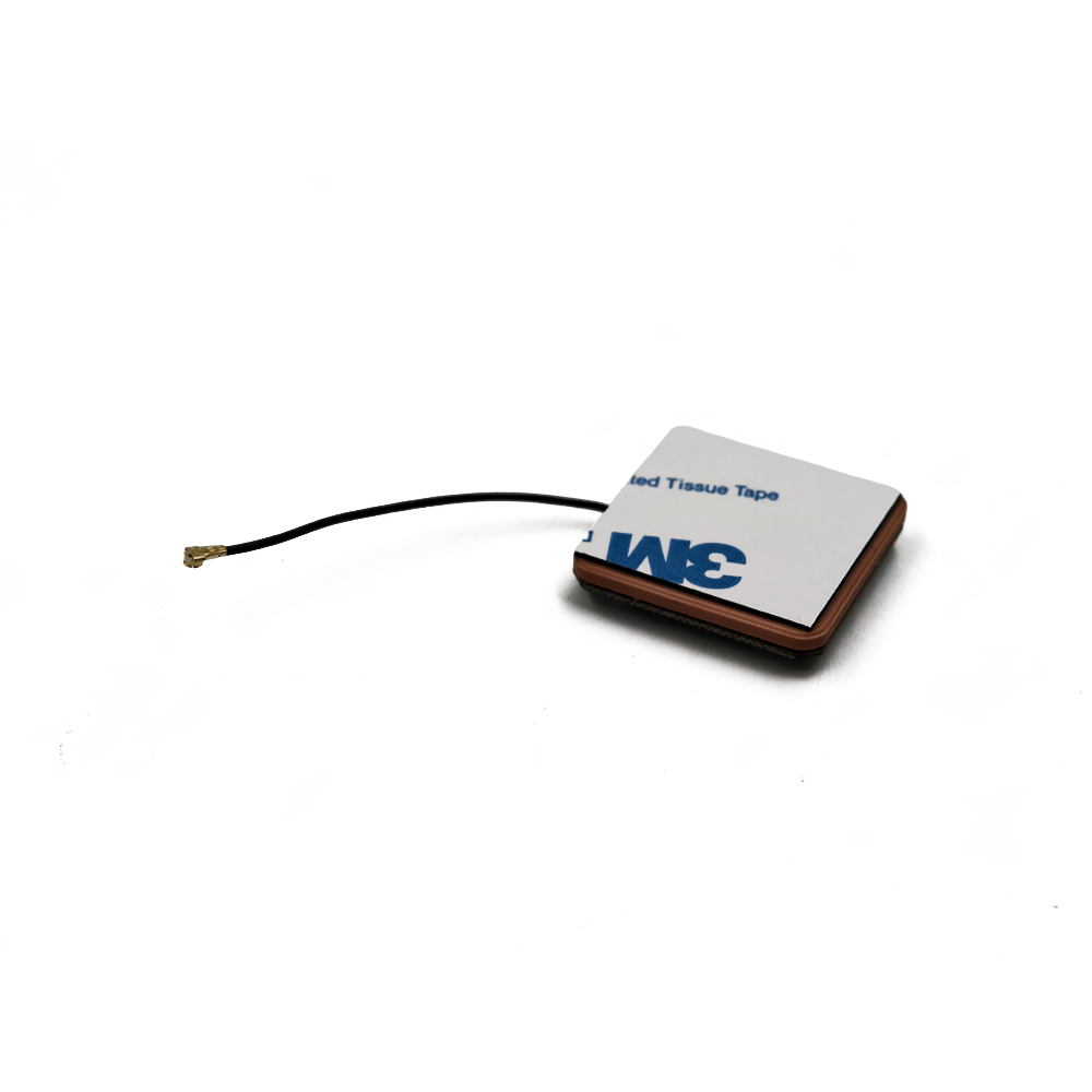
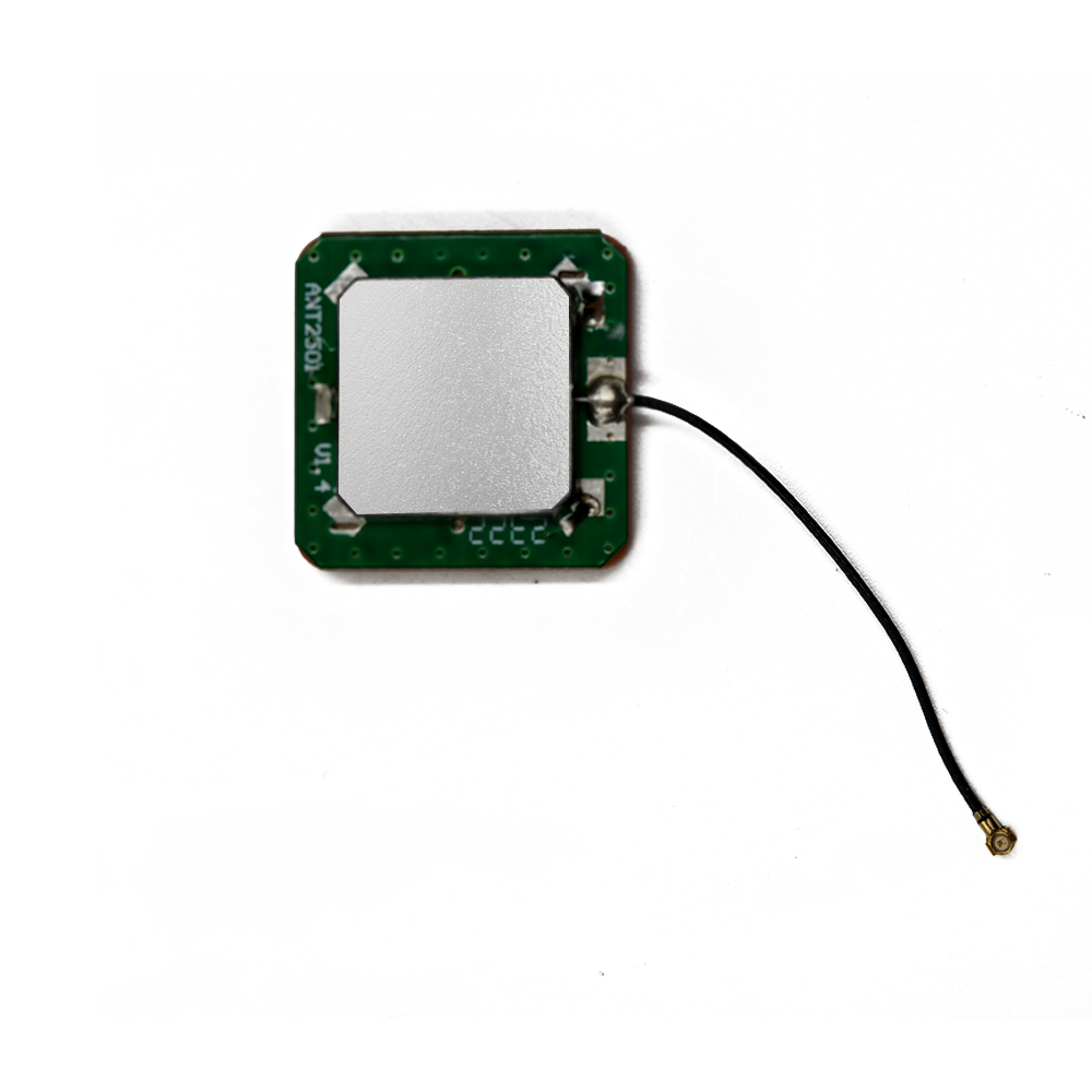
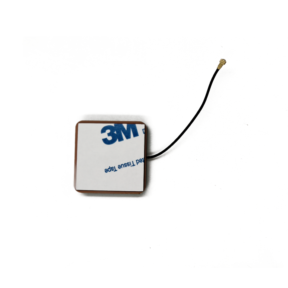
The core of the antenna is the ceramic patch radiator, typically a square or circular dielectric resonator made from high-permittivity ceramic materials such as barium magnesium tantalate (BMT) or BST. The ceramic is sintered and metallized on both top and bottom surfaces—the top serving as the radiating element and the bottom forming part of the ground plane. The thickness and dielectric constant of the ceramic determine the resonant frequency and bandwidth. For multi-band operation, stacked patches or multi-layer ceramic structures are used to resonate at L1, L2, and L5 frequencies simultaneously.
The ground plane is a conductive copper layer beneath the ceramic patch. Its size is optimized to enhance gain and suppress surface waves. In surveying applications, a larger ground plane (typically 1.5x the patch size) improves radiation efficiency and reduces multipath. Some designs include a metal cavity or shielded enclosure to further isolate the antenna from EMI generated by the drone’s onboard electronics.
The feed mechanism connects the patch to the active circuitry. Probe feeding is the most common method, where a coaxial pin passes through the ground plane and connects to the center of the patch. This ensures good impedance matching (typically 50 Ω) and stable performance across the operating band.
The active circuitry is housed in a miniature module attached to the feed point. It includes a low-noise amplifier (LNA) with a noise figure below 1 dB and gain of 20–30 dB, implemented using GaAs or SiGe semiconductor technology. Bandpass filters are integrated to reject interference from cellular, Wi-Fi, or other RF sources. DC power is supplied via a bias-tee, allowing the LNA to be powered through the same coaxial cable used for RF signal transmission.
Manufacturing involves precision processes such as tape casting, laser trimming, and surface-mount technology (SMT). The entire assembly is encapsulated in a UV-resistant radome to protect against moisture, dust, and thermal cycling. Thermal stability is ensured through material selection and mechanical design to minimize phase center drift.
In conclusion, the construction of active ceramic patch antennas reflects a high level of engineering sophistication, tailored to meet the exacting demands of surveying drones.
The operation of an active ceramic patch antenna is rooted in the principles of electromagnetic resonance, signal amplification, and noise suppression—engineered to deliver high-fidelity GNSS signal reception for precision surveying applications. Understanding its working principles is essential to appreciating its role in enabling centimeter-level positioning accuracy in UAV-based geospatial systems.
At the core of the antenna is the ceramic patch radiator, a dielectric resonator that functions as a half-wavelength resonant cavity. When GNSS signals from orbiting satellites (e.g., GPS, Galileo, BeiDou) impinge on the patch, they induce oscillating electric fields between the top metallized surface and the ground plane beneath. Due to the high dielectric constant (εᵣ ≈ 20–40) of the ceramic material, the effective wavelength within the substrate is significantly reduced, allowing the antenna to resonate at GNSS frequencies (e.g., L1 at 1575.42 MHz) while maintaining a compact physical size—typically 25–35 mm per side. This resonance generates a standing wave pattern, with maximum electric field intensity at the center of the patch, which is then coupled to the feed point via a coaxial probe or microstrip line.
The radiation pattern of the patch is inherently directional, with maximum gain in the zenith direction (perpendicular to the patch surface). This hemispherical coverage is ideal for surveying drones, as it maximizes reception from satellites above the horizon while minimizing sensitivity to ground reflections and multipath signals from below. The typical gain ranges from 3 to 6 dBi, with a wide beamwidth (≈120°) that ensures consistent signal lock during drone maneuvers such as banking turns or pitch variations.
However, GNSS signals arrive at the Earth’s surface with extremely low power—often as weak as -130 dBm—making them susceptible to degradation from cable losses and electronic noise. This is where the active component of the antenna becomes critical. Integrated directly at the feed point is a Low-Noise Amplifier (LNA), which amplifies the received RF signal before it travels through the coaxial cable to the GNSS receiver. By amplifying the signal early in the chain, the LNA ensures that the signal-to-noise ratio (SNR) is preserved, even when long cables or lossy connectors are used. This is particularly important in surveying drones, where the antenna may be mounted on the top of the airframe while the receiver is located in the payload bay.
The LNA is designed with a very low noise figure (typically <1 dB) to minimize the addition of thermal noise. It also features high linearity to avoid distortion when strong out-of-band signals (e.g., from 4G/5G transmitters) are present. Bandpass filters are integrated before and after the LNA to reject interference outside the GNSS bands (e.g., 1559–1610 MHz for L1), further enhancing signal purity.
Power for the LNA is delivered via a bias-tee, a circuit that superimposes DC voltage (usually 3–5 V) onto the same coaxial cable used for RF signal transmission. At the receiver end, a complementary bias-tee separates the DC power from the RF signal, supplying power to the LNA while passing the GNSS signal to the receiver. This eliminates the need for a separate power cable, simplifying installation and reducing weight—critical factors in drone design.
Another key aspect of the working principle is phase center stability. In high-precision applications like RTK and PPK surveying, even sub-millimeter variations in the apparent signal reception point (phase center) can introduce positioning errors. The symmetric geometry of the ceramic patch, combined with uniform dielectric properties and precise manufacturing, ensures that the phase center remains stable across different satellite elevation angles and temperature conditions. Some advanced antennas include phase center calibration data stored in firmware, which the GNSS receiver uses to correct for residual offsets.
The antenna also supports multi-frequency and multi-constellation operation. Dual-band designs use stacked patches or multi-layer ceramic structures to resonate at both L1 and L5 frequencies simultaneously. This enables ionospheric delay correction by comparing signal propagation times across frequencies, significantly improving positioning accuracy. Access to multiple constellations (GPS, GLONASS, Galileo, BeiDou) increases the number of visible satellites, enhancing reliability and reducing convergence time for RTK solutions.
In dynamic flight conditions, the antenna must maintain consistent performance despite vibration, temperature fluctuations, and changing electromagnetic environments. The ceramic substrate’s thermal stability and mechanical rigidity help mitigate detuning, while shielding and filtering protect against EMI from motors, ESCs, and cameras.
In summary, the active ceramic patch antenna functions as a highly optimized front-end sensor for GNSS signals. It captures weak satellite transmissions, amplifies them with minimal noise addition, filters out interference, and delivers a clean, stable signal to the receiver. This entire process occurs within milliseconds, enabling real-time, high-precision positioning that is fundamental to the success of UAV-based surveying missions.
Active ceramic patch antennas offer a compelling set of advantages for surveying drones, but they also come with engineering trade-offs that must be carefully managed.
Advantages
1. High Signal Sensitivity and SNR Improvement
The integrated LNA boosts weak GNSS signals at the source, preserving SNR and enabling reliable lock in obstructed environments such as forests or urban areas.
2. Compact and Lightweight Design
Ceramic’s high permittivity allows for miniaturization, making these antennas ideal for small and medium surveying drones where space and payload capacity are limited.
3. Multi-Band and Multi-Constellation Support
Dual- or triple-band operation enables access to L1, L2, and L5 signals, supporting advanced positioning techniques like RTK and PPP with ionospheric correction.
4. Directional Gain and Multipath Rejection
The patch’s hemispherical radiation pattern focuses on skyward signals, reducing ground reflections and improving position accuracy.
5. Phase Center Stability
Critical for high-precision surveying, the stable phase center ensures repeatable and accurate carrier-phase measurements.
6. EMI Resistance
Integrated filtering and shielding protect against interference from onboard electronics, ensuring signal integrity.
7. Simplified Integration
Bias-tee power delivery reduces cabling complexity, facilitating clean and reliable installation.
Challenges
1. Power Dependency
The LNA requires continuous DC power. Voltage drops or power interruptions can cause complete GNSS signal loss, necessitating stable power regulation.
2. Risk of LNA Saturation
Strong out-of-band signals (e.g., from cellular towers) can overload the LNA, causing gain compression or intermodulation distortion.
3. Thermal and Mechanical Sensitivity
Although ceramic is stable, extreme temperatures or mechanical stress can cause slight detuning, affecting resonance and phase center.
4. Cost
Active antennas are more expensive than passive ones due to the LNA, filters, and precision manufacturing.
5. Placement Constraints
Optimal performance requires a clear view of the sky and separation from EMI sources, which can be challenging on compact drone platforms.
6. Cable Quality Dependency
While active antennas reduce cable loss impact, poor-quality or unshielded cables can still introduce noise or signal degradation.
Despite these challenges, the advantages far outweigh the drawbacks for professional surveying applications. With proper system design—stable power, good grounding, and optimal placement—active ceramic patch antennas deliver unmatched performance.
Future Trends
1. AI-Enhanced Signal Processing
Future active antennas may integrate machine learning algorithms to detect and mitigate interference in real time. By analyzing signal patterns, these systems could dynamically adjust filtering or gain settings to maintain optimal reception in complex RF environments.
2. Multi-Antenna Arrays and Beamforming
Instead of a single patch, future surveying drones may use arrays of ceramic patches with beamforming capabilities. This would allow the antenna to electronically steer its reception pattern toward stronger satellite signals or null out sources of interference, significantly improving reliability in urban or forested areas.
3. Integration with Inertial Navigation Systems (INS)
Tighter fusion between GNSS antennas and high-grade MEMS or fiber-optic gyroscopes will enable robust navigation during signal outages (e.g., flying under bridges or tree canopies). The stable phase center of ceramic patches enhances the accuracy of such GNSS/INS integration.
4. Miniaturization and Conformal Designs
Advances in ceramic materials and 3D printing may lead to ultra-thin, flexible, or conformal antennas that can be embedded into drone fuselages or wings without compromising aerodynamics or aesthetics.
5. Enhanced Multi-Frequency Support
As new GNSS signals become available (e.g., GPS L6, Galileo E6), active ceramic antennas will evolve to support additional bands, enabling even more robust ionospheric correction and faster ambiguity resolution.
6. Quantum-Inspired Positioning Assistance
While still in research, quantum accelerometers and gravimeters may one day complement GNSS. High-stability active antennas will remain essential for aligning and calibrating these next-generation sensors.
7. Autonomous and BVLOS Operations
For drones flying Beyond Visual Line of Sight (BVLOS), precise and reliable positioning is a regulatory requirement. Active ceramic patch antennas will be critical in enabling safe, autonomous survey missions over large areas.
8. Onboard Edge Processing
Future antennas may include embedded processors that perform real-time signal quality assessment, health monitoring, and data preprocessing, reducing latency and bandwidth requirements.
9. Sustainable Materials and Manufacturing
There is growing interest in eco-friendly ceramic formulations and energy-efficient amplifier designs to reduce the environmental footprint of drone systems.
10. Standardization and Calibration Services
As demand grows, standardized phase center calibration databases and over-the-air testing protocols will emerge, ensuring consistent performance across different manufacturers and models.
These trends point toward a future where active ceramic patch antennas are not just passive signal receivers, but intelligent, adaptive components of a fully integrated navigation ecosystem. Their evolution will parallel advancements in drone autonomy, AI-driven data analysis, and global geospatial infrastructure.
6. Conclusion
Active ceramic patch antennas have become an indispensable technology in the field of drone-based surveying, serving as the cornerstone of high-precision geospatial data collection. By combining the inherent advantages of high-dielectric ceramic materials with integrated low-noise amplification, these antennas deliver the signal fidelity, phase stability, and environmental resilience required for centimeter-level positioning accuracy.
Their compact size, multi-band capability, and directional gain make them ideally suited for integration into modern surveying drones, which must operate efficiently in challenging environments ranging from dense urban canyons to remote mountainous regions. The ability to support Real-Time Kinematic (RTK) and Post-Processed Kinematic (PPK) techniques ensures that aerial imagery and LiDAR data are accurately georeferenced, enabling reliable outputs for mapping, construction, agriculture, and environmental monitoring.
While challenges such as power dependency, electromagnetic interference, and cost remain, ongoing advancements in materials science, microelectronics, and signal processing are steadily addressing these limitations. The integration of AI, beamforming, and multi-sensor fusion promises to elevate the performance of active antennas beyond current capabilities, transforming them from passive components into intelligent navigation nodes.
As the demand for accurate, timely, and scalable geospatial data continues to grow—driven by smart cities, climate monitoring, and autonomous systems—the role of active ceramic patch antennas will only become more critical. They represent not just a technological solution, but a foundational enabler of the digital transformation in surveying and earth observation.
In conclusion, the active ceramic patch antenna is more than a component; it is a key enabler of precision, reliability, and innovation in the rapidly evolving world of surveying drones. As drone technology advances toward full autonomy and global deployment, these antennas will remain at the forefront, ensuring that every pixel captured from the sky is precisely where it should be.

 86 0755 2819 9597
Lucy Yang | lucy.y@toxutech.com
Nicole Li | nicole@toxutech.com
Dotty Zhao | sales04@toxutech.com
Global Business Director / Sales Team / Global Operations


 En
En Cn
Cn Korean
 Home >


