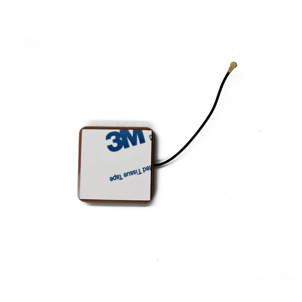
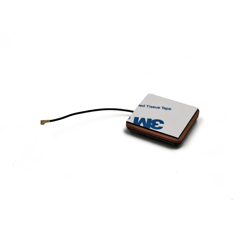
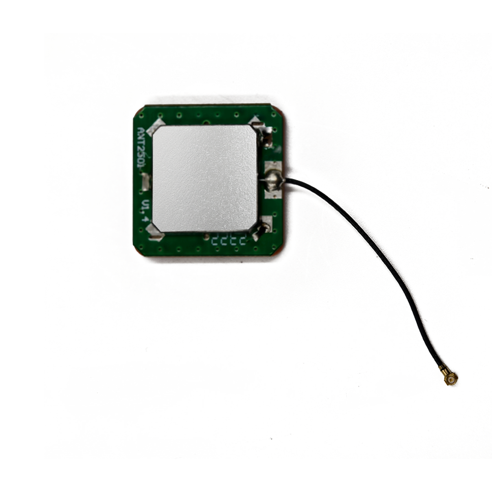
Overview
An active multi-frequency GNSS ceramic antenna is a significant leap from its single-band predecessor. It is a single, compact device engineered to simultaneously receive and amplify a wide spectrum of satellite signals across multiple frequency bands. Its core mission is to serve as the critical front-end for high-precision applications, enabling technologies like Real-Time Kinematic (RTK) and Precise Point Positioning (PPP) that demand multi-frequency data to achieve centimeter-level accuracy.
The driving force behind this technology is the principle of multi-frequency measurement. Single-frequency receivers are susceptible to a key source of error: the ionospheric delay. The ionosphere, a layer of the atmosphere, slows down GNSS signals in a frequency-dependent manner. By measuring the same signal on two different frequencies (e.g., L1 and L5), a receiver can precisely calculate and eliminate this ionospheric error. Furthermore, access to the new, modernized signals (like GPS L5 and Galileo E5) provides higher power, better correlation properties, and improved resistance to interference and multipath.
Designing an antenna to handle this wide bandwidth is a formidable challenge. A standard single-band ceramic patch antenna is a high-Q, resonant structure tuned to a very specific frequency like L1 (1575.42 MHz). To cover additional bands like L2 (1227.60 MHz) and L5 (1176.45 MHz), which are hundreds of megahertz apart, requires a radical rethinking of the antenna's architecture. Engineers can no longer rely on a simple, single resonant patch; they must employ sophisticated techniques such as stacked patches, slotted patches, or coupled feeds to create multiple resonance points within a single, compact form factor.
These antennas are the enabling technology for the next generation of compact, high-precision devices. They are found in surveying equipment, precision agriculture guidance systems, drone navigation modules, autonomous vehicle testing platforms, and scientific instrumentation. By providing a clean, amplified, and coherent set of signals from all available satellites across all bands, they allow advanced receivers to perform the complex calculations that yield unparalleled position, velocity, and time (PVT) solutions. This overview establishes the multi-frequency active ceramic antenna not just as an incremental improvement, but as a transformative technology that brings professional-grade accuracy into smaller, more power-efficient, and more cost-effective platforms.
Design and Construction
The design and construction of a multi-frequency active ceramic antenna is a complex exercise in electromagnetic engineering, materials science, and miniaturization. It pushes the boundaries of what is possible within a small ceramic substrate, requiring innovative techniques to break the fundamental trade-offs between size, bandwidth, and efficiency.
1. The Multi-Resonant Radiating Element:
The core challenge is moving beyond a single resonance. The standard solution is the stacked patch antenna.
Architecture: This design features two or more ceramic patches stacked vertically and separated by a dielectric layer. The top patch is typically smaller and is electromagnetically coupled (not physically connected) to a larger bottom patch.
Principle: Each patch is tuned to a different fundamental frequency. The larger, lower patch resonates at a lower frequency (e.g., L5/L2 band), while the smaller, upper patch resonates at a higher frequency (e.g., L1 band). The coupling between them allows a single feed point to excite both resonances simultaneously. This structure effectively creates a dual-band antenna from a single feed.
Tri-Band Designs: For covering L1, L2, and L5, even more complex designs are used. This can involve a triple-stack, or more commonly, using a single patch with multiple slots or notches. Introducing precisely calculated slots into a patch can perturb the current paths, creating multiple separate resonance modes within the same physical patch. For instance, a corner-truncated patch or a patch with a U-shaped slot can be designed to resonate at three distinct frequencies.
2. Advanced Ceramic Materials:
The ceramic substrate is more critical than ever.
Dielectric Constant (Dk): While a high Dk (e.g., 20-40) is used for extreme miniaturization in single-band antennas, it comes at the cost of reduced bandwidth. Multi-band antennas often use moderate-Dk ceramics (e.g., 9-20) to achieve the necessary bandwidth for each resonance without excessive loss.
Low Loss Tangent: To maintain high radiation efficiency across all bands, the ceramic must have an exceptionally low loss tangent. Any inefficiency is multiplied across multiple bands, leading to a weak signal output.
Temperature Stability: The dielectric constant must be stable over a wide temperature range (-40°C to +85°C is standard). Frequency drift in one band due to temperature change can detune the antenna and degrade performance.
3. The Wideband Low-Noise Amplifier (LNA):
The "active" component must now be a wideband amplifier.
Broadband Matching: The LNA's input matching network is no longer tuned to a single frequency point. It must present a 50-ohm impedance and a low noise figure across the entire spectrum of interest, from ~1160 MHz (L5) to ~1600 MHz (L1). This requires complex matching circuits with multiple components.
Gain Flatness: The LNA must provide uniform gain across all bands. If the gain is significantly higher at L1 than at L5, it can unbalance the receiver's tracking loops.
Linearity and Blocking: With a wider front-end bandwidth, the antenna is exposed to more potential interferers. The LNA and any front-end filtering must have high linearity (high IP3) to avoid being desensitized by strong out-of-band signals from cellular, Wi-Fi, or other services.
4. Integrated Bandpass Filtering:
To protect the wideband LNA from out-of-band interference, integrated filtering is essential. However, designing a filter that passes a wide swath of spectrum (e.g., 1160-1600 MHz) while rejecting nearby cellular bands (e.g., 1710-2170 MHz for 3G/4G) is challenging. Often, a broad bandpass filter is used followed by a diplexer or triplexer. This is a frequency-dependent switch that splits the incoming wideband signal into separate paths for different frequency groups (e.g., one path for L5/L2, another for L1) before amplification, allowing for more optimized filtering and amplification in each chain.
5. Phase Center Stability and Calibration:
For precision applications, the stability of the antenna's phase center—the electrical point from which measurements are taken—is paramount. A multi-frequency antenna must have a stable and well-defined phase center for each frequency band it supports. Any movement of the phase center with frequency (phase center offset) or with the angle of signal arrival (phase center variation) introduces error into the carrier-phase measurements used for RTK. Manufacturers perform meticulous anechoic chamber testing to characterize these variations and provide calibration data (in ANTEX format) so the receiver can correct for them mathematically.
Working Principles
The operational principle of a multi-frequency antenna extends beyond simple amplification to the coherent harvesting of a wide spectrum of signals, enabling advanced error-correction techniques.
1. Simultaneous Multi-Frequency Reception:
The stacked-patch or slotted-patch design allows a single feed point to excite multiple resonant modes. When RF energy from a GPS L1, Galileo E5a, and BeiDou B2 signal arrives simultaneously, the antenna structure oscillates at these different frequencies concurrently. The resulting electrical currents at the feed point constitute a complex composite signal containing all the information from all satellites on all bands. This is a key advantage over using multiple single-band antennas: it ensures that the phase relationships between signals from the same satellite but different frequencies are preserved, as they pass through a single physical point. This coherence is vital for precise differential measurements.
2. Wideband Amplification and Conditioning:
The composite signal, containing energy from ~1160 MHz to ~1600 MHz, is fed into the wideband LNA. The LNA's primary function remains the same: to apply gain with minimal added noise. However, it must do so equally across this 440 MHz wide spectrum. The amplified signal is then often sent through a diplexer. The diplexer acts like a set of filters that split the signal into two or more streams:
Low-Band Stream: Contains signals from L5 (1176.45 MHz), L2 (1227.60 MHz), E5a/b (1191.795-1207.14 MHz), etc.
High-Band Stream: Contains signals from L1 (1575.42 MHz), E1 (1575.42 MHz), B1 (1561.098 MHz), etc.
These separate streams can then be processed by separate LNAs or sent to a multi-channel receiver.
3. Enabling Advanced Positioning Algorithms:
The ultimate value of this antenna is realized in the receiver's algorithms:
Ionospheric Delay Correction: This is the primary benefit. The receiver measures the code and carrier phase on two frequencies (e.g., L1 and L2). Because the ionospheric delay is inversely proportional to the square of the frequency, the delay on L1 and L2 is different. By comparing the two measurements, the receiver can calculate the total electron content (TEC) in the signal path and eliminate almost all of the ionospheric error from the position solution.
Faster and More Robust RTK Fix: RTK relies on resolving integer ambiguities in the carrier phase measurement. Using a third frequency (e.g., L5) creates extra-wide-lane combinations with wavelengths so long that the integer ambiguity can be resolved almost instantaneously, dramatically reducing the "time to fix" and making the system more robust against signal interruptions.
Multipath Mitigation: The new civil signals (L5, L2C, E5) have longer codes and higher chipping rates, making them inherently more resistant to multipath interference. The antenna's ability to receive these signals provides the receiver with more robust data to work with.
4. Coherence and System Performance:
By providing all frequency bands from a single physical point (the antenna phase center), the system avoids the complexities and errors introduced by using multiple, spatially separated antennas. The phase relationships between all signals are physically preserved, allowing the receiver to perform highly accurate differential comparisons between frequencies and across constellations, which is the foundation of modern, high-precision GNSS.
Advantages and Challenges
-
Advantages:
Unmatched Accuracy: Enables precise ionospheric error correction, which is the largest source of error in single-frequency GNSS, leading to centimeter-level accuracy with RTK/PPP.
Enhanced Reliability and Robustness: Access to multiple constellations and signals provides significant redundancy. If signals in one frequency band are blocked or degraded, the system can fall back to others, maintaining a continuous and reliable position solution.
Faster Convergence Times: The use of triple-frequency measurements allows for instantaneous resolution of carrier-phase ambiguities in RTK, leading to a near-initial "fix" and re-fix after signal loss.
Improved Multipath Resistance: Provides the receiver with modernized signals (L5, L2C) that are inherently more resistant to multipath, improving accuracy in challenging urban and canyon environments.
System Integration: Replaces the need for multiple independent antennas, simplifying product design, reducing size, and ensuring phase coherence.
Challenges and Limitations:
Design Complexity: The electromagnetic design of a multi-resonant, wideband patch antenna is vastly more complex than a single-band design. It requires sophisticated simulation software and experienced RF engineers.
Cost: The use of multiple ceramic layers, complex feeds, advanced LNAs, and diplexers makes these antennas significantly more expensive to design and manufacture than their single-band counterparts.
Size Trade-off: While still compact, a stacked-patch design is inherently thicker and may have a larger footprint than a single-band antenna. Achieving miniaturization while maintaining wide bandwidth and efficiency is a constant battle.
Power Consumption: A wideband LNA may draw more current than a single-band LNA, and a system with a diplexer and multiple amplifier stages will have higher overall power consumption, a critical factor for battery-operated devices.
Filtering and Interference: The wide front-end is more susceptible to in-band and out-of-band interference, requiring more sophisticated and costly filtering solutions to maintain performance in noisy RF environments.
Applications and Future Trends
-
Applications:
Precision Agriculture: Guidance systems for tractors and harvesters, variable rate application, and autonomous farming machinery.
Surveying and Mapping: High-precision RTK rovers and base stations for cadastral surveying, construction layout, and GIS data collection.
Unmanned Aerial Vehicles (UAVs): Navigation and control for drones used in mapping, surveying, inspection, and delivery, where precise landing and obstacle avoidance are critical.
Autonomous Vehicles and ADAS: Testing, development, and deployment of autonomous driving systems that require robust, centimeter-level positioning.
Scientific and Timing Applications: Geophysics, crustal deformation monitoring, and network synchronization for telecommunications, where PPP is used for precise timing.
Marine and Aviation: High-end navigation systems for harbor maneuvering, dredging, and aerial surveying.
Future Trends:
Further Miniaturization: Ongoing research into materials (e.g., metamaterials) and design techniques (e.g., improved slotting, magneto-dielectric materials) will continue to shrink the form factor of multi-band antennas for use in smartphones and wearables.
Tighter Integration with Receivers: The trend is towards "Antenna-in-Package" (AiP) or "System-in-Package" (SiP) solutions, where the antenna, LNA, filters, and the GNSS receiver IC are integrated into a single module. This optimizes performance and simplifies design for OEMs.
AI-Enhanced Antennas: The integration of basic interferometry or adaptive tuning elements, controlled by AI algorithms on the receiver, could allow the antenna to dynamically adjust its pattern or tuning to mitigate interference and multipath in real-time.
Expanded Bandwidth for New Signals: As constellations modernize and new signals become available (e.g., GPS L1C), antennas will need to support even wider bandwidths, pushing the limits of current technology.
Cost Reduction through Mass Adoption: As high-precision GNSS filters down from professional to consumer markets (e.g., advanced driver-assistance systems, robotics), economies of scale will drive down the cost of multi-frequency antennas.
Conclusion
The active multi-frequency GNSS ceramic antenna is far more than a simple incremental upgrade; it is the cornerstone that enables the entire ecosystem of modern high-precision positioning. By solving the profound engineering challenge of wideband, efficient signal capture in a miniature form factor, it has broken down the barriers that once separated professional, expensive survey-grade equipment from mainstream consumer and industrial applications.
Its ability to provide a coherent, low-noise, multi-band signal feed is what allows advanced algorithms to cancel ionospheric errors, resolve ambiguities instantly, and deliver the robustness and reliability required for safety-critical and autonomy-driving applications. It represents a perfect synergy of materials science, electromagnetic theory, and semiconductor technology.
As the world moves towards greater autonomy—in our vehicles, our agricultural systems, our airspace, and our industries—the demand for ubiquitous, reliable, and precise location data will become non-negotiable. The active multi-frequency ceramic antenna stands as the critical enabling technology at the physical layer that will make this future possible, ensuring that the next generation of devices can truly see their place in the world with unparalleled clarity and accuracy.


 Language
 En
En Cn
Cn Korean

 Home >


 18665803017 (Macro)


