

-
Products -PCBA Manufacturing RF Connectors RF Cable Assemblys Embedded Antennas External Antennas Positioning Chips and Modules
RF Connectors

RF Cable Assemblys
Embedded Antennas
External Antennas
Positioning Chips and Modules


 Language


Language


Global Navigation Satellite Systems (GNSS) have become indispensable in modern navigation, positioning, and timing (PNT) technologies. Among the various platforms relying on GNSS, Unmanned Aerial Vehicles (UAVs) represent one of the most rapidly growing and demanding applications.
Global Navigation Satellite Systems (GNSS) have become indispensable in modern navigation, positioning, and timing (PNT) technologies. Among the various platforms relying on GNSS, Unmanned Aerial Vehicles (UAVs) represent one of the most rapidly growing and demanding applications. From commercial drone deliveries to military reconnaissance and precision agriculture, UAVs require highly accurate, reliable, and robust positioning data to operate safely and efficiently. This demand has led to the widespread adoption of active GNSS ceramic antennas, which combine the benefits of ceramic patch technology with integrated low-noise amplification to deliver superior signal reception in challenging environments.
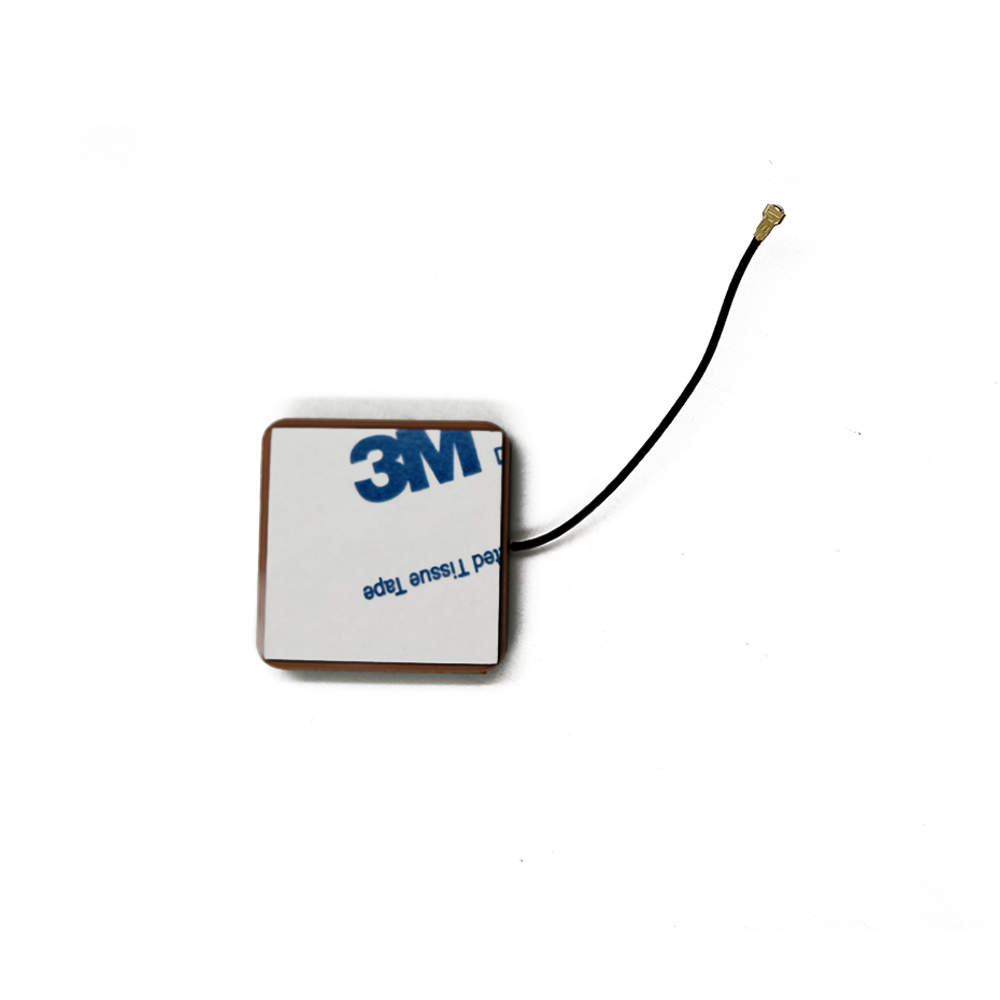
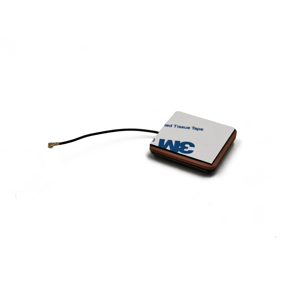
An active GNSS ceramic antenna is a compact, high-performance antenna that integrates a ceramic dielectric resonator with a built-in low-noise amplifier (LNA). The ceramic material, typically composed of barium strontium titanate or similar compounds, provides excellent dielectric properties that enable efficient resonance at GNSS frequencies (e.g., GPS L1 at 1575.42 MHz, GLONASS, Galileo, and BeiDou bands). The "active" designation refers to the inclusion of an LNA directly at the antenna feed point, which amplifies the weak incoming satellite signals before transmission through the coaxial cable to the GNSS receiver. This design minimizes signal loss and noise degradation, which is critical for UAVs operating at high altitudes or in signal-challenged urban and forested areas.
The integration of active GNSS ceramic antennas in UAVs addresses several key challenges. First, UAVs are inherently small and lightweight, limiting the size and power consumption of onboard components. Active ceramic antennas are ideal due to their compact footprint, low profile, and minimal power requirements—typically in the range of 3 to 5 volts with current draws under 20 mA. Second, UAVs often operate in dynamic flight conditions involving rapid orientation changes, multipath interference, and variable signal strength. The directional gain and stable phase center of ceramic patch antennas, enhanced by the LNA, ensure consistent signal tracking and improved position accuracy.
Moreover, modern UAVs frequently operate in multi-GNSS environments, requiring compatibility with multiple satellite constellations. Active ceramic antennas are designed to support dual- or multi-band operation (e.g., L1/L5 or L1/L2), enabling access to a larger number of satellites and improving geometric dilution of precision (GDOP). This multi-frequency capability also allows for ionospheric error correction, further enhancing positioning accuracy to centimeter-level when combined with Real-Time Kinematic (RTK) or Precise Point Positioning (PPP) techniques.
The evolution of UAV applications has driven innovation in GNSS antenna technology. Early UAVs often used simple passive antennas, which were prone to signal degradation over long cable runs and in noisy electromagnetic environments. The shift to active antennas represents a significant advancement, offering improved signal-to-noise ratio (SNR), better multipath rejection, and higher reliability. Additionally, active antennas are less sensitive to impedance mismatches and cable losses, making them more suitable for integration into complex UAV airframes with limited space for antenna placement.
Another critical aspect is electromagnetic compatibility (EMC). UAVs are densely packed with electronic systems—motors, power electronics, cameras, and communication modules—all of which generate electromagnetic interference (EMI). Active GNSS ceramic antennas are designed with shielding and filtering to mitigate EMI, ensuring that the sensitive GNSS signals are not overwhelmed by onboard noise. The ceramic substrate itself provides inherent EMI shielding, while the integrated LNA includes filtering stages to reject out-of-band interference.
From a system integration perspective, active GNSS ceramic antennas simplify the design of UAV navigation systems. By amplifying the signal at the source, they allow for longer cable runs without significant degradation, enabling flexible placement of the antenna on the UAV (e.g., on top of the fuselage for optimal sky view) while locating the GNSS receiver elsewhere in the airframe. This flexibility is crucial for achieving optimal radiation patterns and minimizing blockage from motors or batteries.
In summary, active GNSS ceramic antennas have become a cornerstone of modern UAV navigation systems. Their combination of high gain, compact size, low power consumption, and robust performance in dynamic and noisy environments makes them ideally suited for the demanding requirements of UAV operations. As UAV applications continue to expand into beyond visual line of sight (BVLOS), urban air mobility (UAM), and autonomous flight, the role of high-performance GNSS antennas will only grow in importance. Future developments are expected to focus on miniaturization, multi-constellation support, and integration with other sensing modalities such as inertial navigation systems (INS) and 5G networks.
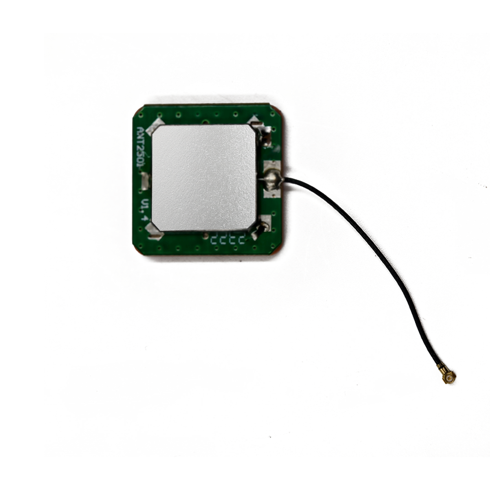
The design and construction of active GNSS ceramic antennas involve a sophisticated integration of materials science, electromagnetic engineering, and microelectronics. These antennas are engineered to deliver high gain, wide bandwidth, and excellent phase stability while maintaining a compact form factor suitable for UAV integration. The construction process typically includes four key components: the ceramic radiating element, ground plane, feed network, and the active circuitry (LNA and filtering).
The core of the antenna is the ceramic patch, a rectangular or circular dielectric resonator made from high-permittivity ceramic materials such as barium magnesium tantalate (BMT) or barium strontium titanate (BST). These materials are chosen for their high dielectric constant (typically between 20 and 40), which allows for miniaturization of the antenna while maintaining resonance at GNSS frequencies. The ceramic patch is metallized on its top and bottom surfaces—the bottom serving as part of the ground plane and the top acting as the radiating element. The thickness and permittivity of the ceramic determine the resonant frequency and bandwidth.
The ground plane is a conductive layer beneath the ceramic patch, usually made of copper. Its size and shape are critical for determining the antenna’s radiation pattern and impedance matching. For UAV applications, the ground plane is often designed to be slightly larger than the patch to enhance gain and suppress surface waves. In some designs, a cavity or shielded enclosure is added around the patch to further improve isolation and reduce multipath effects.
The feed mechanism connects the ceramic patch to the active circuitry. Common feeding techniques include probe feeding, microstrip line feeding, and aperture coupling. In UAV-grade active antennas, probe feeding is most common due to its simplicity and good impedance matching. A coaxial probe passes through the ground plane and connects directly to the center of the patch. This point is then connected to the input of the LNA.
The active circuitry is housed in a small module directly attached to the feed point. It typically includes a low-noise amplifier (LNA), bandpass filters, DC biasing circuitry, and sometimes a gain control stage. The LNA is the heart of the active antenna, providing 20–30 dB of gain with a noise figure below 1 dB. It is usually implemented using gallium arsenide (GaAs) or silicon germanium (SiGe) semiconductor processes for optimal high-frequency performance. Bandpass filters are integrated to reject out-of-band interference from cellular, Wi-Fi, or other RF sources commonly found in UAV environments.
Power for the LNA is supplied through the same coaxial cable that carries the RF signal (a technique known as bias-tee operation). A DC blocking capacitor prevents the DC bias from reaching the GNSS receiver, while an RF choke allows the DC current to power the LNA without affecting the RF signal path. This design minimizes the number of connections and simplifies integration.
Manufacturing these antennas involves precision processes such as tape casting for ceramic substrates, laser trimming for tuning, and surface-mount technology (SMT) for assembling the active components. The entire assembly is often encapsulated in a protective radome made of UV-resistant plastic to withstand environmental conditions such as moisture, dust, and temperature extremes—critical for UAVs operating in diverse climates.
Thermal stability is another key design consideration. The ceramic material exhibits low thermal expansion and stable dielectric properties over a wide temperature range (typically -40°C to +85°C), ensuring consistent performance during UAV flight. Additionally, the antenna housing is designed to minimize thermal gradients that could affect phase center stability.
In multi-band designs, stacked ceramic patches or multi-layer structures are used to resonate at multiple frequencies (e.g., L1 and L5). These require careful electromagnetic simulation and tuning to ensure isolation between bands and consistent radiation patterns.
In conclusion, the design and construction of active GNSS ceramic antennas represent a convergence of advanced materials, RF engineering, and miniaturized electronics. Their robust construction and optimized performance make them ideally suited for the rigorous demands of UAV navigation.
Active GNSS ceramic antennas have emerged as a critical enabling technology for high-performance UAV navigation systems. Their integration into modern unmanned platforms offers a range of compelling advantages that directly address the unique operational demands of aerial robotics. However, like any advanced technology, they also present certain engineering and operational challenges that must be carefully managed to ensure optimal system performance.
Advantages
1. Enhanced Signal Sensitivity and Improved Signal-to-Noise Ratio (SNR)
One of the most significant advantages of active GNSS ceramic antennas is their ability to amplify weak satellite signals at the point of reception. GNSS signals transmitted from satellites in medium Earth orbit (MEO) arrive at the Earth’s surface with extremely low power—typically between -125 dBm and -130 dBm. In UAV applications, where the platform may be flying at high altitudes, in urban canyons, or under dense foliage, signal attenuation can further reduce received power. The integrated low-noise amplifier (LNA) in an active antenna boosts the signal level immediately after reception, effectively overcoming losses in the coaxial feed line and preserving the signal-to-noise ratio (SNR). This early-stage amplification is crucial because it prevents the weak GNSS signal from being overwhelmed by thermal noise introduced in subsequent stages of the RF chain. As a result, UAVs equipped with active antennas can maintain lock on more satellites for longer durations, even in challenging environments, leading to improved positioning accuracy and continuity.
2. Compact Size and Low Profile
Ceramic patch antennas are inherently compact due to the high dielectric constant of the ceramic material, which allows for a smaller resonant structure compared to traditional quarter-wave or half-wave antennas. This miniaturization is essential for UAVs, where space, weight, and aerodynamic drag are critical design constraints. Active GNSS ceramic antennas typically measure between 20 mm and 40 mm per side, with a height of less than 10 mm, making them ideal for integration on small drones, multirotors, and fixed-wing UAVs. Their low profile allows for flush mounting on the top surface of the fuselage, minimizing wind resistance and avoiding interference with propellers or landing gear.
3. Directional Gain and Hemispherical Coverage
The ceramic patch design provides directional gain, typically between 3 dBi and 6 dBi, focused toward the zenith (skyward direction). This radiation pattern is highly beneficial for UAVs, which require strong reception from satellites above the horizon while minimizing ground reflections and multipath interference from below. The hemispherical coverage ensures that the antenna maintains a consistent view of the GNSS constellation as the UAV maneuvers through pitch, roll, and yaw. Combined with the LNA’s gain, this directional performance enables reliable tracking of low-elevation satellites, which are often critical for maintaining a good geometric dilution of precision (GDOP).
4. Multi-Band and Multi-Constellation Support
Modern active ceramic antennas are increasingly designed to support dual- or triple-frequency operation (e.g., GPS L1/L5, Galileo E1/E5a, or BeiDou B1/B2). This capability allows UAVs to access signals from multiple satellite constellations (GPS, GLONASS, Galileo, BeiDou), significantly increasing the number of visible satellites and improving position solution robustness. Multi-frequency reception also enables advanced error correction techniques, such as ionospheric delay compensation, which is essential for achieving centimeter-level accuracy in Real-Time Kinematic (RTK) and Precise Point Positioning (PPP) applications. These high-precision capabilities are vital for UAVs used in surveying, mapping, precision agriculture, and autonomous navigation.
5. Electromagnetic Interference (EMI) Resistance
UAVs are electromagnetically noisy environments, with motors, power converters, cameras, and communication systems generating broadband RF interference. Active GNSS ceramic antennas are designed with built-in filtering and shielding to reject out-of-band noise. The ceramic substrate itself acts as a natural EMI shield, while the integrated LNA includes bandpass filters that attenuate signals outside the GNSS frequency bands. Additionally, the use of a bias-tee for DC power delivery over the same coaxial cable reduces the number of connectors and potential entry points for interference. This inherent EMI resilience ensures that the GNSS receiver receives a clean, amplified signal, even in electrically hostile environments.
6. Stable Phase Center and High Repeatability
For high-precision applications, the stability of the antenna’s phase center—the apparent point from which signals are received—is critical. Active ceramic antennas exhibit excellent phase center stability over temperature, frequency, and angle of arrival, which minimizes measurement errors in carrier-phase-based positioning. This stability is achieved through precise manufacturing, symmetric patch geometry, and controlled dielectric properties. As a result, these antennas are widely used in UAVs that require repeatable and accurate positioning, such as those employed in photogrammetry, LiDAR scanning, and geospatial data collection.
Challenges
1. Power Dependency and Reliability Concerns
Unlike passive antennas, active antennas require a continuous DC power supply (typically 3–5 V) to operate the LNA. This introduces a single point of failure: if the power supply is interrupted or unstable, the antenna ceases to function, leading to a complete loss of GNSS signal. In UAVs, where power systems may experience voltage fluctuations due to motor load changes or battery discharge, this dependency necessitates careful power regulation and redundancy planning. Additionally, the LNA itself can fail due to electrostatic discharge (ESD) or thermal stress, especially in harsh operating environments.
2. Risk of LNA Saturation and Intermodulation
The LNA, while essential for signal amplification, is susceptible to saturation when exposed to strong out-of-band signals. In urban environments, high-power transmissions from cellular base stations, Wi-Fi routers, or radar systems can overload the amplifier, causing it to compress or distort the GNSS signal. This can result in loss of lock or degraded positioning accuracy. To mitigate this, active antennas must include robust filtering and high linearity in the LNA design. However, achieving both high gain and high linearity simultaneously is a challenging trade-off that increases design complexity and cost.
3. Thermal Drift and Environmental Sensitivity
Although ceramic materials are thermally stable, prolonged exposure to extreme temperatures—such as those experienced during high-altitude flights or in desert environments—can cause slight shifts in the dielectric constant, leading to detuning of the antenna. This thermal drift can affect resonance frequency and phase center stability, introducing small but significant errors in high-precision applications. Additionally, moisture ingress or mechanical stress from vibration can degrade performance over time, necessitating robust sealing and mechanical design.
4. Cost and Complexity
Active GNSS ceramic antennas are more expensive than their passive counterparts due to the inclusion of active electronics, precision manufacturing, and rigorous testing. For cost-sensitive commercial UAVs, this can be a limiting factor. Furthermore, integrating an active antenna requires careful attention to power supply design, grounding, and impedance matching, increasing the complexity of the overall system architecture.
5. Integration and Placement Limitations
While compact, the antenna must still be placed in a location with a clear view of the sky and away from sources of EMI. On small UAVs, finding an optimal mounting position that avoids blockage from motors, batteries, or carbon fiber structures can be difficult. Poor placement can lead to pattern distortion, multipath, or signal nulls, negating the benefits of the active design.
In summary, while active GNSS ceramic antennas offer transformative advantages in sensitivity, accuracy, and reliability for UAVs, their successful deployment requires careful consideration of power, interference, thermal, and integration challenges. Ongoing advancements in materials, filtering, and system-level design are helping to mitigate these limitations, making active antennas increasingly viable across a broader range of UAV applications.
Current Applications
Active GNSS ceramic antennas are now integral to a wide range of UAV applications, spanning commercial, industrial, military, and scientific domains.
1. Surveying and Mapping
UAVs equipped with RTK-capable GNSS systems use active ceramic antennas to achieve centimeter-level positioning accuracy. This enables high-resolution topographic mapping, 3D modeling, and cadastral surveying without the need for ground control points. Applications include land development, mining, and infrastructure inspection.
2. Precision Agriculture
In agriculture, UAVs use GNSS-guided flight paths to monitor crop health, apply fertilizers, and map soil conditions. Active antennas ensure consistent signal lock during low-altitude flights over uneven terrain, enabling precise variable-rate application and yield optimization.
3. Delivery and Logistics
Autonomous delivery drones rely on continuous, high-integrity GNSS positioning for route planning, obstacle avoidance, and safe landing. Active antennas enhance reliability in urban environments where signal blockage and multipath are common.
4. Military and Security
Reconnaissance, surveillance, and target acquisition (RSTA) UAVs require secure, jam-resistant positioning. Active antennas with multi-constellation support and anti-jamming features are critical for mission success in contested environments.
5. Urban Air Mobility (UAM) and BVLOS Operations
Future air taxis and long-range drones operating beyond visual line of sight (BVLOS) will depend on resilient PNT systems. Active GNSS antennas, combined with inertial navigation and 5G/6G networks, will form the backbone of such systems.
Future Trends
1. Multi-Sensor Fusion
Future UAVs will integrate GNSS with inertial measurement units (IMUs), vision systems, and LiDAR to create hybrid navigation solutions that remain functional during GNSS outages.
2. AI-Driven Signal Processing
Machine learning algorithms will be used to detect and mitigate interference, predict signal degradation, and optimize antenna performance in real time.
3. Miniaturization and Chip-Scale Antennas
Advances in materials and fabrication techniques will lead to smaller, lighter antennas with embedded intelligence and self-calibration capabilities.
4. 5G and Satellite Communication Integration
Hybrid positioning using GNSS and terrestrial networks (e.g., 5G NR positioning) will enhance accuracy and availability in urban canyons and indoor environments.
5. Quantum and Alternative PNT
Research into quantum sensors and alternative navigation methods may eventually complement or replace GNSS, but active ceramic antennas will remain essential for the foreseeable future.
Conclusion
Active GNSS ceramic antennas represent a pivotal advancement in UAV navigation technology. By combining the electromagnetic efficiency of ceramic patch radiators with the signal-boosting capability of integrated low-noise amplifiers, these antennas deliver the high sensitivity, accuracy, and reliability required for modern unmanned flight. Their compact size, multi-band support, and resistance to interference make them ideally suited for the diverse and demanding environments in which UAVs operate—from dense urban landscapes to remote agricultural fields and high-altitude surveillance missions.
The advantages of active antennas—enhanced SNR, stable phase centers, and robust performance in weak-signal conditions—directly contribute to the safety, efficiency, and autonomy of UAV operations. They enable advanced capabilities such as RTK and PPP, which are essential for high-precision applications in surveying, mapping, and autonomous navigation. Moreover, their compatibility with multiple GNSS constellations ensures global coverage and improved satellite geometry, reducing the risk of positioning outages.
However, the deployment of these antennas is not without challenges. Power dependency, susceptibility to interference, thermal sensitivity, and integration complexity require careful engineering and system-level design. As UAV technology evolves toward greater autonomy and longer-range operations, the demands on GNSS systems will only increase. Future developments in multi-sensor fusion, AI-enhanced signal processing, and hybrid positioning will further elevate the role of active antennas within the broader navigation ecosystem.
In conclusion, active GNSS ceramic antennas are not merely components but enablers of the next generation of UAV capabilities. Their continued innovation and integration will be instrumental in unlocking the full potential of unmanned aerial systems across commercial, industrial, and defense applications. As we move toward a future of autonomous skies, the active GNSS ceramic antenna will remain a cornerstone of reliable, precise, and resilient navigation.

 86 0755 2819 9597
Lucy Yang | lucy.y@toxutech.com
Nicole Li | nicole@toxutech.com
Dotty Zhao | sales04@toxutech.com
Global Business Director / Sales Team / Global Operations


 En
En Cn
Cn Korean
 Home >


