

-
Products -PCBA Manufacturing RF Connectors RF Cable Assemblys Embedded Antennas External Antennas Positioning Chips and Modules
RF Connectors

RF Cable Assemblys
Embedded Antennas
External Antennas
Positioning Chips and Modules


 Language


Language


The Wideband GNSS RTK Ceramic Patch Antenna is a ubiquitous and critically important component in the ecosystem of high-precision positioning. It represents the modern evolution of antenna technology, engineered to meet the demanding requirements of Real-Time Kinematic (RTK) and other carrier-phase-based GNSS techniques. As the name implies, its defining characteristics are its "wideband" capability, enabling it to receive multiple satellite navigation frequencies, and its construction around a "ceramic" substrate, which offers superior electromagnetic performance. This antenna type has become the workhorse for a vast array of professional applications, from surveying and mapping to autonomous machinery, striking an exceptional balance between performance, form factor, cost, and durability.
The shift from single-frequency GPS to multi-constellation, multi-frequency GNSS (encompassing GPS, GLONASS, Galileo, BeiDou, and others) fundamentally changed antenna requirements. A modern RTK system no longer relies on just the L1 frequency; it leverages L2, L5, E1, E5a, E5b, E6, B1, B2, and more to achieve faster integer ambiguity resolution, higher accuracy, and unparalleled robustness. A wideband antenna is designed to operate efficiently across this entire spectrum, typically from about 1150 MHz to 1650 MHz, without significant degradation in performance. This is a non-trivial engineering challenge, as traditional antenna designs are often optimized for a narrow frequency range.
The "patch" element refers to its physical structure: a flat, typically square or circular, radiating element. This low-profile design is inherently robust, lightweight, and easy to manufacture, making it ideal for portable and embedded applications. However, the simple patch antenna suffers from inherent limitations like narrow bandwidth and sensitivity to its environment. This is where the "ceramic" substrate comes into play. By using a specialized ceramic material with a high dielectric constant (εr), engineers can shrink the physical size of the antenna while simultaneously improving its bandwidth and performance characteristics. The high dielectric constant allows the electromagnetic waves to wavelength within the material, meaning a physically smaller patch can resonate at the desired low GNSS frequencies.
The primary mission of this antenna, like all RTK-grade antennas, is to faithfully capture the phase of the carrier wave from the satellite signals. Any distortion or instability in the phase measurement at the antenna will translate directly into a positional error. Therefore, every aspect of its design—from the purity of the ceramic material to the geometry of the feed point and the design of the ground plane—is optimized for phase center stability. This means the electrical point from which the signal appears to be received must remain constant, regardless of the satellite's azimuth or elevation angle. A stable phase center allows for accurate calibration and correction, which is the bedrock of centimeter-level accuracy.
In essence, the Wideband GNSS RTK Ceramic Patch Antenna is a masterpiece of miniaturization and performance optimization. It is the enabling technology that allows high-precision GNSS to be integrated into everything from a surveyor's pole and an agricultural drone to a construction robot and a consumer-grade mapping device, providing the reliable, high-fidelity signal needed to unlock the full potential of global satellite navigation systems.
The design and construction of a Wideband GNSS RTK Ceramic Patch Antenna is a sophisticated process that blends materials science, electromagnetic theory, and precision manufacturing. Its architecture is a multi-layered system where each component plays a vital role in achieving wideband performance and phase stability.
1. The Ceramic Substrate:
The core of the antenna is the ceramic substrate. This is not ordinary ceramic but a carefully formulated material with specific properties:
High Dielectric Constant (εr): Values typically range from 20 to 40. This high εr confines the electromagnetic fields closer to the patch, significantly reducing the antenna's physical size compared to one built on a standard fiberglass (FR4) substrate. A smaller size is crucial for portable and embedded applications.
Low Loss Tangent (tan δ): This measures how much energy is lost as heat within the dielectric material itself. A very low loss tangent (e.g., < 0.002) is essential for maintaining efficiency. High losses would attenuate the already weak GNSS signals, degrading the signal-to-noise ratio (SNR) and overall performance.
Temperature Stability: The dielectric constant must remain stable over a wide temperature range (-40°C to +85°C is typical). Temperature fluctuations can detune the antenna's resonant frequency; a stable substrate ensures consistent performance in any weather.
2. The Radiating Patch:
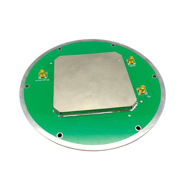
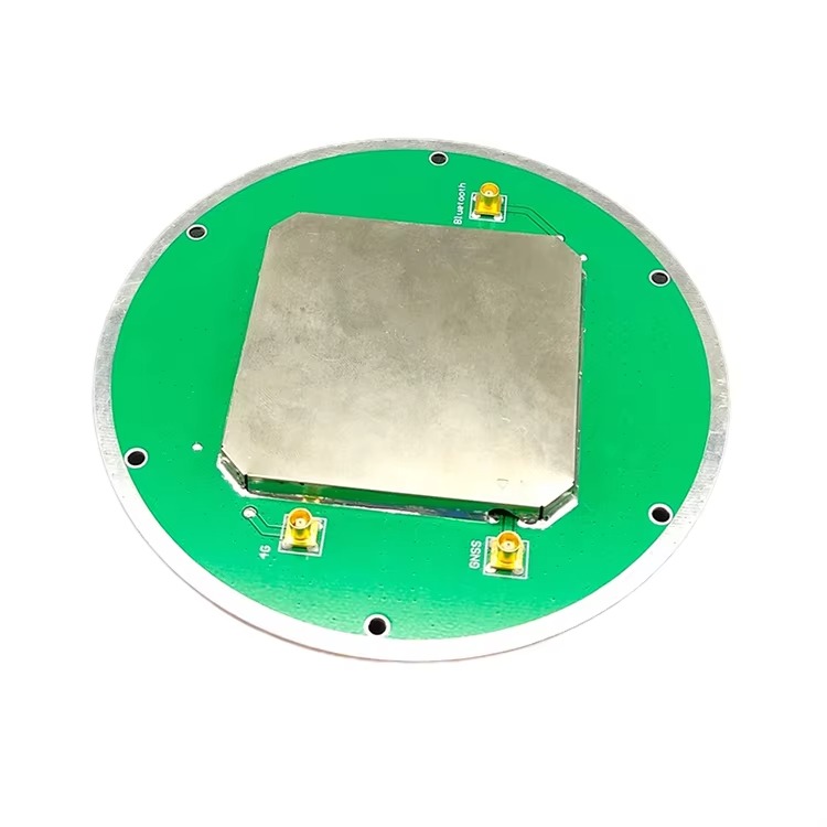
This is a thin layer of conductive material (often silver or copper) printed or fired onto the top surface of the ceramic substrate. The patch's geometry (usually a square, circle, or rounded square) is precisely calculated to determine the fundamental resonant frequency. For wideband operation, a single patch is insufficient. The most common design is the stacked patch or coupled patch.
Stacked Patch: This design features two or more ceramic layers, each with its own patch. The lower, larger patch is primarily tuned to lower frequencies (e.g., L2, L5), while the upper, smaller patch is tuned to higher frequencies (e.g., L1). The patches are electromagnetically coupled, creating multiple resonant points that merge to form a wide operating bandwidth.
Coupled Feed: Instead of physically connecting the coaxial cable directly to the patch, a coupling slot or strip in the ground plane is often used. This technique enhances bandwidth and simplifies impedance matching.
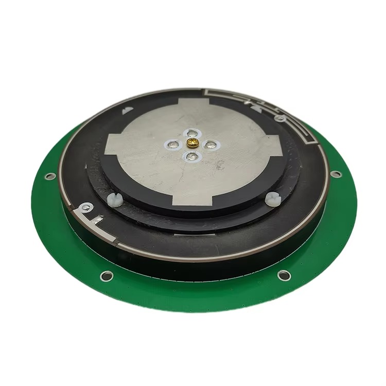
3. The Ground Plane:
Beneath the ceramic substrate lies a continuous layer of conductor that forms the antenna's ground plane. This is a critical component that:
Defines the antenna's radiation pattern, directing energy upward towards the sky.
Provides a stable electrical reference point for the radiating patch.
Shields the antenna from noise and interference emanating from the electronics below it (e.g., the receiver itself).
The size and quality of the ground plane are paramount for achieving a stable phase center and a consistent, hemispherical radiation pattern.
4. The Low-Noise Amplifier (LNA):
An integral, high-performance LNA is mounted directly within the antenna housing, typically on a small printed circuit board (PCB) below the ground plane. Its functions are:
Amplification: To boost the extremely weak GNSS signals (typically around -130 dBm) by 25-40 dB.
Noise Reduction: To have an exceptionally low noise figure (often < 1.5 dB), meaning it adds almost no additional noise of its own.
Filtering: To include bandpass filtering that rejects strong out-of-band interference from cellular, WiFi, and radio transmitters.
The LNA is powered via phantom power supplied through the center conductor of the coaxial cable from the receiver.
5. The Housing and Radome:
The entire delicate assembly is encapsulated in a protective housing. The top part acts as a radome—a cover that is transparent to GNSS radio frequencies. For high-end antennas, this radome is often made from the same ceramic as the substrate to ensure perfect electromagnetic compatibility and to protect the patch. More commonly, it is made from a high-quality, low-loss plastic like ABS or polycarbonate. The housing is sealed to be waterproof (IP67 or higher), dustproof, and UV-resistant, ensuring longevity in harsh outdoor environments.
6. The External Ground Plane (Optional):
While the internal ground plane is key, many high-precision patch antennas are designed to be mounted on a larger external ground plane (e.g., a 70x70mm or 100x100mm metal plate). This further stabilizes the antenna's performance, improves its gain pattern, and enhances its multipath rejection capabilities. For ultimate performance, some designs incorporate a choke ring structure into the base, which creates a high-impedance barrier to low-angle reflected signals.
The construction is a precise balance: the ceramic enables miniaturization and wide bandwidth, the stacked-patch design realizes that bandwidth, the LNA ensures signal integrity, and the rugged housing provides the robustness required for field use.
The Wideband GNSS RTK Ceramic Patch Antenna operates on the fundamental principles of a microstrip patch antenna, but its wideband and high-stability performance is achieved through advanced engineering. Its primary job is to convert electromagnetic waves into electrical currents with minimal distortion of the signal's phase.
1. Resonance and Radiation:
The antenna works by creating a resonant cavity between the metallic patch and the ground plane, with the ceramic substrate acting as the dielectric filler. When the dimensions of the patch are approximately half a wavelength in the dielectric material (which is shorter due to the high εr), it resonates at a specific frequency. At resonance, currents oscillate along the length of the patch, and fringing fields at its edges couple into free space, radiating energy. The stacked-patch design creates multiple, overlapping resonant cavities, each tuned to a different segment of the GNSS band. These overlapping resonances combine to provide a smooth, wide bandwidth of operation, allowing a single antenna to efficiently radiate and receive all GNSS frequencies from ~1150 MHz to 1650 MHz.
2. Right-Hand Circular Polarization (RHCP):
GNSS satellites transmit RHCP signals to mitigate signal polarization rotation caused by the ionosphere and to provide a means of rejecting reflections. The patch antenna generates RHCP through a carefully designed feed mechanism. The two most common techniques are:
Single-Feed with Perturbations: A single feed point is placed off-center, and diagonal slots or notches are cut into the patch. This disrupts the natural linear polarization and excites two orthogonal modes with a 90-degree phase difference, creating circular polarization.
Dual-Feed: Two feed points are located on orthogonal edges of the patch. They are fed with signals that are 90 degrees out of phase, directly generating a circularly polarized wave. This method typically provides better axial ratio (a measure of polarization purity) but is more complex to implement.
3. Phase Center Stability:
This is the most critical operational principle for an RTK antenna. The Phase Center is the hypothetical point in space from which the transmitted or received radiation appears to originate. For precision phase measurements, this point must be constant. Any movement of the phase center with satellite direction (azimuth and elevation) or frequency introduces a measurable range error.
The ceramic patch antenna achieves stability through:
Symmetry: A perfectly symmetrical patch and feed structure.
A Large, Stable Ground Plane: This provides a consistent electrical reference, minimizing pattern distortion.
Precise Manufacturing: Consistency in the ceramic material and patch geometry is paramount.
Manufacturers use anechoic chambers to meticulously measure the phase center variations (PCV) across all frequencies and angles. This PCV data is used to create an correction model that is applied within the receiver's firmware, mathematically moving the measurements to a single, stable reference point.
4. Multipath Rejection:
While not as inherently robust as a helical antenna with a choke ring, the patch antenna mitigates multipath through:
Radiation Pattern: It has a natural hemispherical pattern with maximum gain at the zenith (straight up) and reduced gain towards the horizon. Since direct signals come from above and multipath often arrives from low angles, this pattern provides inherent attenuation of reflected signals.
Polarization Purity: A good axial ratio means the antenna is highly sensitive to RHCP and rejects Left-Hand Circular Polarized (LHCP) waves, which are typically generated by single-bounce reflections.
5. Signal Chain:
The incoming RHCP wave induces a tiny current in the patch. This current is transferred via the feed to the LNA, where it is amplified with minimal added noise. The amplified signal is then sent down the coaxial cable to the receiver. The active design ensures that cable losses do not degrade the signal-to-noise ratio before it reaches the receiver's sensitive analog-to-digital converters.
In summary, the antenna works by acting as a wideband, phase-stable, efficient transducer, ensuring that the receiver is provided with the cleanest possible signal for achieving rapid and reliable integer ambiguity resolution.
The Wideband GNSS RTK Ceramic Patch Antenna offers a compelling set of advantages that have made it the dominant form factor, but it also faces specific challenges that designers and users must contend with.
Advantages:
Compact and Low Profile: The high dielectric constant of the ceramic allows for a very small physical size. This miniaturization is its greatest advantage, enabling integration into portable equipment, drones, smartphones, and autonomous vehicles where space and weight are at a premium.
Wideband Performance: A single, well-designed stacked-patch antenna can cover the entire GNSS spectrum. This simplifies system design, reduces cost compared to using multiple antennas, and ensures consistent performance across all constellations and frequencies, which is critical for modern RTK.
Robust Mechanical Construction: The solid ceramic substrate and rugged housing make the antenna highly resistant to vibration, shock, and physical impact. This durability is essential for field use in surveying, agriculture, and construction environments.
Cost-Effectiveness at Scale: While the ceramic material is more expensive than FR4, the design is highly amenable to automated, high-volume manufacturing processes like screen printing and firing. This makes it economically viable for mass production, offering excellent performance at a reasonable cost.
Consistent Hemispherical Pattern: The radiation pattern is well-suited for receiving signals from satellites across the entire sky, from horizon to horizon. This is ideal for applications where the antenna's orientation may change, such as on a moving vehicle or rover pole.
Good Multipath Rejection (with a ground plane): When mounted on a sufficient ground plane (typically 70mm x 70mm or larger), the antenna's pattern sharpens, providing better rejection of low-angle multipath signals.
Challenges:
Ground Plane Dependency: The antenna's performance—its gain pattern, impedance matching, and most importantly, its phase center stability—is highly dependent on the size and quality of the ground plane it is mounted on. Placing it on a small or irregularly shaped ground plane (e.g., a small plastic housing) can severely degrade its performance, making it unsuitable for RTK work.
Limited Ultimate Multipath Rejection: While good, its inherent multipath rejection is generally inferior to a purpose-built geodetic antenna with a large choke ring. In severe multipath environments (e.g., deep urban canyons), it may struggle compared to these more specialized designs.
Thermal Sensitivity: Although ceramic substrates are chosen for stability, they still exhibit a non-zero thermal coefficient. Extreme temperature variations can cause slight shifts in the dielectric constant, leading to small changes in the antenna's resonant frequency and phase center. High-end models mitigate this through sophisticated material choices and design.
Bandwidth vs. Size Trade-off: While "wideband," there is always a trade-off. Covering an extremely wide band (e.g., from 1.1 to 1.6 GHz) with high efficiency in a very small form factor remains a significant engineering challenge. Performance at the band edges can sometimes be compromised.
Quality Variation: The market is flooded with ceramic patch antennas of varying quality. Low-cost variants may use inferior ceramic with high loss tangents, poorly designed LNAs with high noise figures, or inadequate grounding, leading to poor performance that is not immediately obvious to the end-user but fatal for RTK.
In conclusion, its advantages of small size, wide bandwidth, and ruggedness make it the ideal all-rounder for most RTK applications. However, users must be aware of its need for a proper ground plane and its performance limitations in extreme multipath scenarios compared to larger, more specialized antennas.
The Wideband GNSS RTK Ceramic Patch Antenna's blend of performance, size, and cost has made it the enabling technology for a revolution in high-precision location across countless industries.
Applications:
Professional Surveying and Mapping: This is the core application. It is mounted on tripods (as a base station) and on rover poles, providing the accuracy needed for cadastral surveying, topographic mapping, construction layout, and GIS data collection. Its portability is key for field surveyors.
Precision Agriculture (AgriTech): It is embedded into guidance systems for tractors, combines, and sprayers, enabling auto-steer and variable-rate application. It is also used on drones for crop health monitoring and field mapping. The ruggedness to withstand dust, moisture, and vibration is critical.
Unmanned Aerial Vehicles (UAVs): The small size and light weight make it the default choice for RTK and PPK on drones. This allows for the creation of highly accurate digital surface models, orthomosaics, and 3D models without the need for numerous ground control points, revolutionizing aerial surveying.
Construction and Machine Control: These antennas are installed on bulldozers, graders, excavators, and pile drivers for machine guidance and control systems. They provide the real-time centimeter-level accuracy needed to bring digital design models to life on the job site.
Autonomous Vehicles and Robotics: From prototype self-driving cars and autonomous delivery robots to precision lawn mowers and warehouse logistics robots, this antenna provides the essential absolute positioning that complements other sensors like LiDAR and IMUs.
Consumer and Geofencing Applications: As costs have decreased, these antennas have begun appearing in higher-end consumer devices for applications like precision photography geotagging, augmented reality (AR) experiences requiring accurate location, and strict geofencing for security or commercial purposes.
Future Trends:
Tighter Integration and "Antenna-in-Package": The trend is towards even greater miniaturization and integration. We will see the antenna, LNA, and even portions of the RF front-end integrated into a single, compact module that can be easily embedded into any device, much like a WiFi or Bluetooth module is today.
AI-Enhanced Performance: Future systems will use artificial intelligence to dynamically characterize the antenna's performance in real-time based on the signals it receives. AI could adaptively filter multipath or correct for phase center variations in software based on the live signal environment.
Multi-Sensor Fusion Hubs: The antenna will evolve from a standalone component into a centralized "hub" that also incorporates other sensors like an IMU, magnetometer, and barometric pressure sensor. This provides a fully integrated positioning, navigation, and timing (PNT) solution in a single package.
Enhanced Resilience to Interference: With the radio frequency spectrum becoming more crowded, future designs will incorporate more advanced filtering techniques and potentially adaptive null-steering capabilities to suppress jamming and interference signals directionally.
Materials Innovation: Research into new ceramic composites and substrate materials will continue, aiming for even higher dielectric constants, lower loss tangents, and perfect thermal stability to push the boundaries of performance in smaller sizes.
LEO and GNSS Fusion: As navigation from Low Earth Orbit satellite constellations (e.g., Starlink) becomes a reality, future wideband antennas will be designed to receive these signals as well. Their wide bandwidth may already cover these new frequencies, or will be extended to do so, creating a truly ubiquitous and robust PNT solution.
The ceramic patch antenna will remain at the heart of the precision positioning industry, continuously evolving to become smaller, smarter, and more integrated, powering the next wave of autonomous technology.
Conclusion
The Wideband GNSS RTK Ceramic Patch Antenna stands as a testament to the power of innovative engineering in overcoming physical constraints. It has successfully solved the critical challenge of providing wideband, multi-constellation support in a compact, robust, and cost-effective form factor. By leveraging the properties of advanced ceramic materials and sophisticated stacked-patch design, it delivers the phase-stable performance required for centimeter-level RTK accuracy, which has become the standard for professional positioning.
Its dominance is not due to being the absolute best in any single metric of performance—specialized geodetic antennas with large choke rings will always have superior multipath rejection—but due to its unparalleled ability to deliver excellent all-around performance where it matters most: in a practical, portable, and integratable package. It is the key technology that has democratized high-precision GNSS, moving it from a niche, geodetic tool into the hands of surveyors, farmers, construction workers, and robotics engineers worldwide.
The antenna's future is bright and intrinsically linked to the trends of autonomy and digitalization. As machines of all kinds require a precise understanding of their location, the demand for small, reliable, and multifunctional antennas will only grow. The ongoing evolution in materials science, integration techniques, and intelligent signal processing will ensure that the Wideband GNSS RTK Ceramic Patch Antenna continues to meet these demands, solidifying its role as the fundamental sensor upon which the precise positioning of tomorrow is built. It is, and will remain, the workhorse of the high-precision GNSS world.

 86 0755 2819 9597
Lucy Yang | lucy.y@toxutech.com
Nicole Li | nicole@toxutech.com
Dotty Zhao | sales04@toxutech.com
Global Business Director / Sales Team / Global Operations


 En
En Cn
Cn Korean
 Home >


