

-
Products -PCBA Manufacturing RF Connectors RF Cable Assemblys Embedded Antennas External Antennas Positioning Chips and Modules
RF Connectors

RF Cable Assemblys
Embedded Antennas
External Antennas
Positioning Chips and Modules


 Language


Language


Global Navigation Satellite Systems (GNSS) have become an integral part of modern life, enabling a wide range of applications from navigation in cars and smartphones to precise positioning in surveying and agriculture. At the heart of any GNSS receiver is the antenna, which plays a crucial role in capturing the weak signals transmitted by satellites. Among the various types of GNSS antennas, the wideband GNSS ceramic patch antenna has emerged as a popular choice due to its unique characteristics.
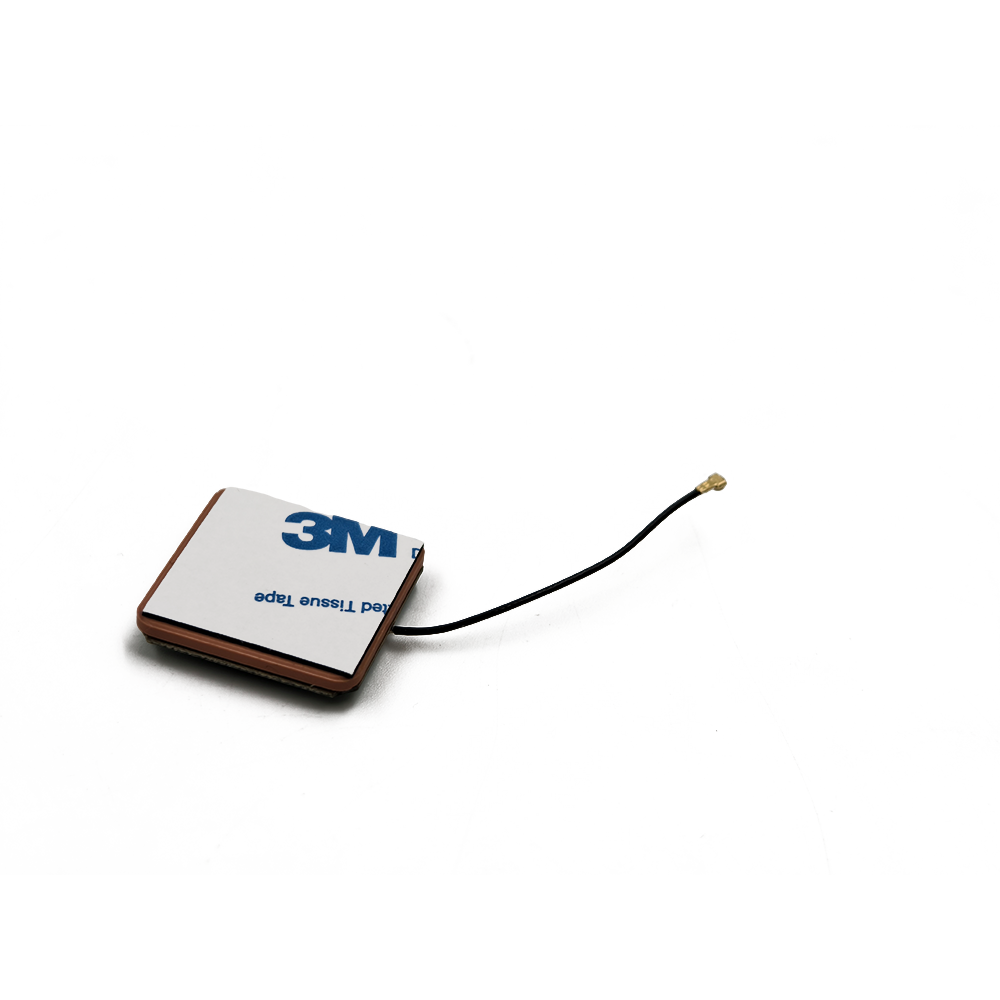
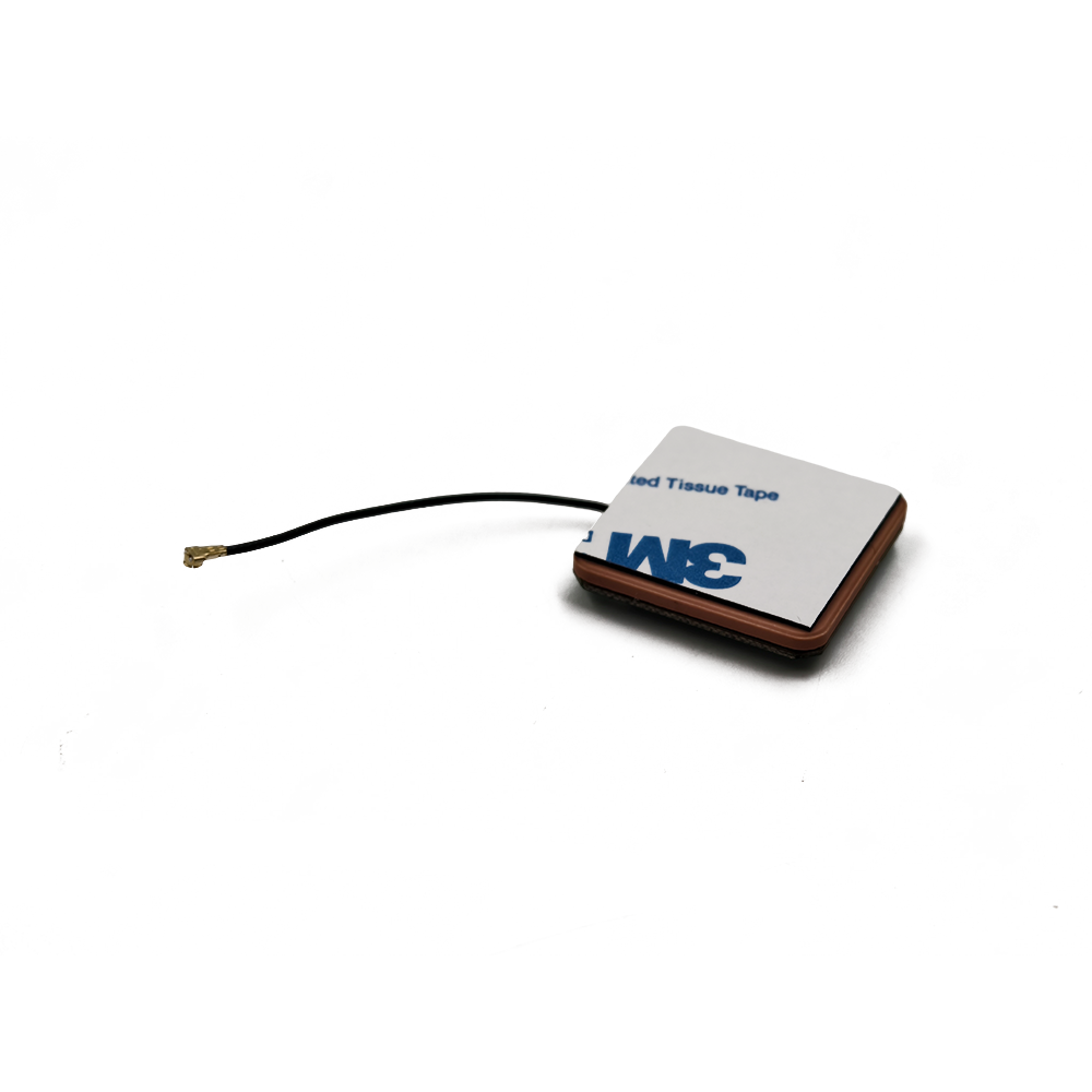
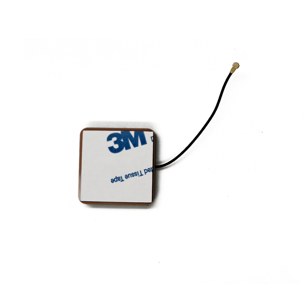
Ceramic patch antennas are a type of microstrip antenna. They consist of a radiating patch, typically made of a metalized pattern on a ceramic substrate, and a ground plane. The ceramic substrate provides several advantages. Firstly, it has a high dielectric constant, which allows for a compact antenna design. A higher dielectric constant means that the electrical size of the antenna can be reduced while maintaining its performance, making it suitable for applications where space is limited, such as in small handheld devices or embedded systems. Secondly, ceramic materials offer good thermal stability. In GNSS applications, the antenna may be exposed to different environmental conditions, and temperature variations can affect the performance of the antenna. The thermal stability of the ceramic substrate helps to ensure that the antenna's electrical properties remain relatively constant over a wide temperature range, providing reliable performance.
The wideband nature of these antennas is a key feature. In the past, GNSS antennas were often designed to operate at a single frequency or a narrow band of frequencies, typically corresponding to the signals of a particular satellite constellation like GPS L1. However, with the development of multi - constellation GNSS receivers that can simultaneously track signals from GPS, GLONASS, Galileo, BeiDou, and other constellations, there is a growing need for antennas that can cover a wide range of frequencies. Wideband GNSS ceramic patch antennas are designed to operate over a broad frequency spectrum, typically spanning from around 1550 MHz to 1620 MHz, which encompasses the main signal bands of most GNSS constellations. This enables a single antenna to receive signals from multiple constellations, improving the availability and accuracy of the GNSS positioning system. For example, in urban environments where satellite signals can be blocked or weakened by buildings, having the ability to receive signals from multiple constellations through a wideband antenna increases the chances of obtaining a reliable position fix.
Moreover, wideband GNSS ceramic patch antennas are widely used in various industries. In the automotive industry, they are used in in - vehicle navigation systems, providing accurate positioning for drivers. The compact size and wideband capabilities of these antennas make them suitable for integration into the vehicle's dashboard or roof without taking up too much space. In the aerospace industry, they are used in aircraft navigation systems, where reliable and accurate positioning is crucial for flight safety. In addition, they find applications in outdoor recreational devices such as hiking GPS units and drones, enabling users to track their location precisely in different terrains.
2.1 Radiating Patch Design
The radiating patch is a fundamental component of the wideband GNSS ceramic patch antenna. It is usually a square or circular metal - coated pattern on the ceramic substrate. The shape and size of the radiating patch are carefully designed to resonate at the desired frequencies within the wide GNSS frequency band. For a square patch, the side length \(L\) is related to the resonant frequency \(f\) by the formula \(L=\frac{c}{2\sqrt{\epsilon_{eff}}f}\), where \(c\) is the speed of light in free space and \(\epsilon_{eff}\) is the effective dielectric constant of the substrate - air combination. The effective dielectric constant takes into account the dielectric properties of the ceramic substrate and the fact that part of the electromagnetic field extends into the air above the patch.
To achieve wideband operation, several techniques can be applied to the radiating patch design. One common approach is to use multiple feed points. A single - feed patch antenna typically has a narrow bandwidth, as the circular polarization bandwidth of a single - feed patch is limited. By using two or more feed points, the circular polarization of the antenna can be significantly improved over a wider bandwidth. For a two - feed point antenna, orthogonal currents flowing on the metalized surface of the patch are detected independently in both axes, one feed for each axis. The two signals are then combined using a 90 - degree hybrid coupler to reconstruct the GNSS information from the satellite. This setup allows the antenna to better receive circularly polarized signals, which are the type of signals transmitted by GNSS satellites, over a broader frequency range.
Another technique for wideband operation is the use of stacked patches. Multiple patches can be stacked on top of each other, with each patch tuned to a different frequency or frequency band within the GNSS spectrum. For example, one patch may be designed to resonate at the GPS L1 frequency (1575.42 MHz), while another patch above it can be tuned to the Galileo E1 frequency (1575.42 MHz) or other relevant frequencies. The stacked patches are electrically isolated from each other but interact electromagnetically to create a wider overall operating bandwidth. This design also helps in improving the gain and radiation pattern characteristics of the antenna across the wide frequency band.
2.2 Ceramic Substrate Selection
The choice of ceramic substrate is crucial for the performance of the wideband GNSS ceramic patch antenna. Ceramic materials with a high dielectric constant are preferred. Common ceramic materials used in antenna design include alumina (\(Al_2O_3\)) and certain types of ferrite ceramics. Alumina, for instance, has a dielectric constant in the range of 9 - 10, which allows for a more compact antenna design compared to using a substrate with a lower dielectric constant like a typical printed circuit board (PCB) material.
The thickness of the ceramic substrate also plays an important role. A thinner substrate generally results in a higher - quality factor (\(Q\)) of the antenna, which is related to the sharpness of the resonance. However, a very thin substrate may be more difficult to manufacture and may also lead to higher ohmic losses. On the other hand, a thicker substrate can increase the bandwidth of the antenna but may also cause a decrease in the radiation efficiency. Therefore, a trade - off needs to be made between the substrate thickness, bandwidth, efficiency, and manufacturability. In practice, substrate thicknesses in the range of 1 - 5 mm are commonly used for wideband GNSS ceramic patch antennas.
In addition to the dielectric constant and thickness, the ceramic substrate should also have good mechanical properties. It needs to be able to withstand the manufacturing process, which may involve processes such as soldering, without cracking or deforming. Moreover, it should be resistant to environmental factors such as humidity and temperature variations to ensure long - term reliability of the antenna.
2.3 Ground Plane Design
The ground plane is an essential part of the wideband GNSS ceramic patch antenna. It serves multiple purposes. Firstly, it reflects the electromagnetic fields radiated by the radiating patch, which helps to direct the radiation in a desired direction, usually upwards towards the satellites. A well - designed ground plane can improve the antenna's gain and radiation pattern. For a patch antenna, the size of the ground plane has a significant impact on its performance. Generally, a larger ground plane can increase the antenna's gain and improve the circular polarization characteristics. However, in many practical applications, space limitations may restrict the size of the ground plane.
In some cases, a partial ground plane or a modified ground - plane structure may be used. For example, a ground - plane with slots or a fractal - like shape can be designed to enhance the antenna's performance within the available space. Slots in the ground plane can be used to tune the antenna's impedance and improve its bandwidth. Fractal - shaped ground planes can increase the electrical size of the ground plane without increasing its physical size, which can be beneficial for compact antenna designs.
The distance between the radiating patch and the ground plane also affects the antenna's performance. This distance, known as the substrate height, is related to the resonant frequency and the impedance of the antenna. A proper substrate height needs to be selected to ensure that the antenna operates efficiently within the wide GNSS frequency band.
2.4 Manufacturing Process
The manufacturing process of wideband GNSS ceramic patch antennas involves several steps. First, the ceramic substrate is prepared. This may involve cutting the ceramic material to the desired size and shape. Then, the metalized pattern for the radiating patch is formed on the ceramic substrate. This can be done through processes such as screen printing, where a conductive ink (usually silver - based) is printed onto the substrate in the shape of the radiating patch. After printing, the substrate is typically fired at a high temperature to cure the conductive ink and form a strong metal - ceramic bond.
If multiple feed points are used, the connection pads for the feed lines need to be accurately formed on the substrate. The feed lines, which are usually made of copper traces on a PCB or coaxial cables, are then connected to the feed points. The ground plane can be either a separate metal plate attached to the bottom of the ceramic substrate or a metalized layer on the opposite side of the substrate if a double - sided ceramic substrate is used.
The antenna may also be encapsulated or protected with a cover to prevent damage from environmental factors. This cover should be made of a material that is transparent to electromagnetic waves, such as certain types of plastics. Finally, the manufactured antennas are tested for their electrical performance, including parameters such as frequency response, gain, and radiation pattern, to ensure that they meet the required specifications for GNSS applications.
3.1 Electromagnetic Wave Interaction
Wideband GNSS ceramic patch antennas operate based on the principles of electromagnetic wave interaction. GNSS satellites transmit circularly polarized electromagnetic waves in the L - band frequencies, typically ranging from 1550 MHz to 1620 MHz. When these waves reach the antenna, the radiating patch of the antenna acts as a resonant circuit. The incident electromagnetic field induces currents on the surface of the radiating patch.
The shape and size of the radiating patch are designed such that it resonates at the frequencies of the GNSS signals. At resonance, the impedance of the radiating patch matches the impedance of the feed line connecting it to the GNSS receiver, allowing for efficient transfer of the received power. The resonance frequency of the patch is determined by its physical dimensions and the dielectric properties of the ceramic substrate. As mentioned earlier, for a square patch, the resonant frequency \(f\) is related to the side length \(L\) and the effective dielectric constant \(\epsilon_{eff}\) of the substrate - air combination.
The currents induced on the radiating patch generate their own electromagnetic fields. These fields interact with the incident fields from the satellites. In a properly designed wideband GNSS ceramic patch antenna, the combination of the induced fields and the incident fields results in a net field that is circularly polarized, which is compatible with the circularly polarized signals transmitted by the satellites. This circular polarization is crucial for efficient signal reception, as it helps to minimize the effects of multi - path propagation.
3.2 Circular Polarization
Circular polarization is a key concept in the operation of wideband GNSS ceramic patch antennas. Circularly polarized waves can be thought of as a combination of two orthogonal linearly polarized waves with a 90 - degree phase difference. In a GNSS system, satellites transmit circularly polarized signals to reduce the impact of multi - path reflections. When a signal reflects off a surface, such as a building or the ground, its polarization may change. However, a circularly polarized receiving antenna is more likely to receive the direct signal from the satellite while rejecting the reflected (multi - path) signals, which often have different polarization characteristics.
To achieve circular polarization in a wideband GNSS ceramic patch antenna, multiple feed points are often used. As described in the design section, with two feed points, orthogonal currents are induced on the radiating patch. These currents are combined with a 90 - degree phase shift, typically using a 90 - degree hybrid coupler. The result is a circularly polarized electromagnetic field radiated or received by the antenna. The use of multiple feed points and the proper combination of the induced currents ensure that the antenna has a good circular polarization performance over a wide frequency band. This wide - band circular polarization capability is essential for the antenna to effectively receive GNSS signals from different constellations, which may operate at slightly different frequencies within the overall GNSS frequency range.
3.3 Signal Reception and Transmission
In a GNSS receiver system, the wideband GNSS ceramic patch antenna is responsible for receiving the weak signals from the satellites. The received signals are then fed through a low - noise amplifier (LNA) to boost their power level before being processed by the GNSS receiver. The LNA is an important component in the front - end of the receiver, as it amplifies the signal while adding as little noise as possible. The noise figure of the LNA directly affects the overall sensitivity of the GNSS receiver system.
Once the signal is amplified, it is further processed by the receiver to extract the navigation information, such as the satellite's position, time, and other data. In some cases, the wideband GNSS ceramic patch antenna may also be used for signal transmission in a two - way communication GNSS system, although this is less common in typical consumer - level applications. For example, in some specialized GNSS - based communication systems for remote monitoring or control, the antenna may be used to transmit short messages or status information back to a central station in addition to receiving satellite signals for positioning.
The antenna's ability to receive signals from multiple constellations simultaneously is a significant advantage. By covering a wide frequency band, it can capture signals from GPS, GLONASS, Galileo, BeiDou, and other constellations. This increases the number of visible satellites in a given location, which in turn improves the accuracy and availability of the GNSS positioning system. For instance, in a dense urban environment where some satellite signals may be blocked by tall buildings, having the ability to receive signals from multiple constellations through a wideband antenna increases the likelihood of obtaining a reliable position fix.
4.1 Advantages
4.1.1 Wideband Operation
One of the most significant advantages of wideband GNSS ceramic patch antennas is their ability to operate over a broad frequency range. This wideband characteristic allows them to receive signals from multiple GNSS constellations simultaneously. For example, they can capture signals from GPS, GLONASS, Galileo, and BeiDou systems, which operate at different frequencies within the L - band. By combining signals from multiple constellations, the accuracy and availability of the GNSS positioning system are greatly enhanced. In urban areas with many obstacles that can block or weaken satellite signals, the wideband antenna can increase the number of visible satellites, improving the chances of obtaining a reliable position fix.
The wideband operation also future - proofs the antenna design. As new GNSS constellations are developed and new frequency bands are allocated for GNSS use, a wideband antenna is more likely to be able to adapt to these changes without the need for a complete redesign. This makes it a cost - effective solution in the long run for applications that require continuous access to the latest GNSS technology.
4.1.2 Compact Size
Ceramic patch antennas, in general, are known for their compact size, and wideband GNSS ceramic patch antennas are no exception. The use of a ceramic substrate with a high dielectric constant allows for a reduction in the physical size of the antenna while maintaining its electrical performance. This compactness makes them ideal for applications where space is limited, such as in smartphones, wearable devices, and small - sized drones. In a smartphone, for example, the antenna needs to be small enough to fit within the device's chassis without sacrificing too much performance. The wideband GNSS ceramic patch antenna can be easily integrated into such devices, providing users with accurate positioning capabilities in a compact form factor.
4.1.3 Good Thermal Stability
Ceramic materials used in these antennas offer good thermal stability. In GNSS applications, the antenna may be exposed to a wide range of temperatures, both in outdoor and indoor environments. Temperature variations can affect the electrical properties of an antenna, leading to changes in its resonant frequency, gain, and radiation pattern. However, the ceramic substrate's thermal stability helps to ensure that the antenna's performance remains relatively consistent over a wide temperature range. This is crucial for applications where reliable positioning is required at all times, such as in automotive navigation systems, where the antenna may experience significant temperature changes during a drive.
4.1.4 Low Cost
Compared to some other types of high - performance GNSS antennas, wideband GNSS ceramic patch antennas are relatively low - cost. The manufacturing process for these antennas, which involves techniques such as screen printing of the radiating patch on the ceramic substrate, is cost - effective. Additionally, the use of common ceramic materials and standard manufacturing processes contributes to their affordability. This low - cost advantage makes them suitable for mass - market applications, such as in consumer electronics like smartphones and handheld GPS devices, where cost is a major consideration for manufacturers.
4.2 Challenges
4.2.1 Limited Radiation Efficiency
One of the challenges associated with wideband GNSS ceramic patch antennas is their relatively limited radiation efficiency compared to some other antenna types. The use of a ceramic substrate, although beneficial for size reduction and thermal stability, can introduce some losses. The dielectric properties of the ceramic material can cause ohmic losses in the antenna, reducing the amount of power that is effectively radiated or received. Additionally, the complex design techniques used to achieve wideband operation, such as multiple feed points and stacked patches, may also contribute to a decrease in radiation efficiency. Improving the radiation efficiency while maintaining the wideband and compact - size characteristics of the antenna is an ongoing research and development challenge.
4.2.2 Sensitivity to Installation Environment
Wideband GNSS ceramic patch antennas are sensitive to their installation environment. The presence of nearby metal objects, for example, can significantly affect their performance. Metal objects can cause signal reflections and interference, distorting the antenna's radiation pattern and reducing its ability to receive signals accurately. In automotive applications, if the antenna is installed too close to metal components in the vehicle, such as the car's body or engine, the signal reception may be degraded. Similarly, in indoor environments, the antenna's performance can be affected by the presence of metal - framed windows or metal - lined walls. Designers need to carefully consider the installation location and environment of the antenna to minimize these negative effects.
4.2.3 Cross - Polarization Suppression
Achieving good cross - polarization suppression is a challenge for wideband GNSS ceramic patch antennas. Cross - polarization occurs when the antenna receives or radiates electromagnetic waves with a polarization that is orthogonal to the desired polarization (in the case of GNSS, the desired polarization is circular). In GNSS applications, cross - polarized signals are often unwanted because they can introduce interference and reduce the signal - to - noise ratio (SNR) of the received desired signals.
GNSS satellites transmit right - hand circularly polarized (RHCP) signals, so the antenna should ideally only receive RHCP signals while rejecting left - hand circularly polarized (LHCP) signals (the cross - polarized component). However, due to the wideband nature of the antenna and the complexity of its design, maintaining high cross - polarization suppression across the entire operating frequency band is difficult. Factors such as manufacturing tolerances, imperfections in the radiating patch pattern, and the influence of the ground plane can all lead to a decrease in cross - polarization suppression.
For example, if the metalized pattern of the radiating patch is not perfectly aligned during the manufacturing process, it can create asymmetries in the antenna's structure. These asymmetries can cause the antenna to radiate or receive a small amount of cross - polarized signals. Similarly, if the ground plane is not properly designed or has irregularities, it can reflect the electromagnetic fields in an uneven manner, further contributing to cross - polarization.
To address this challenge, designers may use advanced simulation tools to optimize the antenna's structure before manufacturing. These tools can model the electromagnetic behavior of the antenna and predict potential cross - polarization issues. Additionally, strict quality control measures during the manufacturing process, such as precise alignment of the radiating patch and careful inspection of the ground plane, can help to minimize cross - polarization. However, even with these measures, achieving consistent and high cross - polarization suppression across the entire wide GNSS frequency band remains a significant technical hurdle.
4.2.4 Interference from Other Signals
Another challenge for wideband GNSS ceramic patch antennas is interference from other signals operating in or near the GNSS frequency band. The L - band, where most GNSS signals are located, is also used by other communication systems, such as some satellite communication (SatCom) systems and terrestrial microwave links. These signals can interfere with the weak GNSS signals received by the antenna, leading to a degradation in the performance of the GNSS receiver.
For instance, a SatCom system operating at a frequency close to the GPS L1 band (1575.42 MHz) can emit signals that are picked up by the wideband GNSS antenna. Since the antenna is designed to operate over a wide frequency range, it may not be able to effectively filter out these interfering signals. The interfering signals can swamp the weak GNSS signals, making it difficult for the receiver to extract the navigation information accurately.
To mitigate this interference, additional filtering components, such as band - pass filters or notch filters, are often integrated into the GNSS receiver system. A band - pass filter can be designed to allow only the GNSS frequency band to pass through to the receiver, while attenuating signals outside of this band. A notch filter, on the other hand, can be used to specifically target and suppress a narrow range of interfering frequencies. However, integrating these filters adds complexity and cost to the system. Moreover, the filters themselves can introduce insertion loss, which reduces the strength of the received GNSS signals. Balancing the need for effective interference suppression with the requirement to maintain signal strength is a key challenge in the design of wideband GNSS ceramic patch antenna systems.
5.1 Applications
5.1.1 Consumer Electronics
The consumer electronics industry is one of the largest users of wideband GNSS ceramic patch antennas. Smartphones, in particular, rely heavily on these antennas to provide location - based services such as navigation, ride - sharing, and location - tagged photos. The compact size of wideband GNSS ceramic patch antennas makes them ideal for integration into the slim and lightweight design of modern smartphones. Additionally, their wideband capability allows smartphones to access signals from multiple GNSS constellations, ensuring accurate positioning even in urban canyons or areas with limited satellite visibility.
Tablet computers and wearable devices, such as smartwatches and fitness trackers, also use wideband GNSS ceramic patch antennas. Smartwatches with built - in GNSS functionality enable users to track their outdoor activities, such as running, cycling, and hiking, with precise location data. The small form factor of the antenna is crucial here, as wearable devices have very limited space for components. The thermal stability of the ceramic substrate is also beneficial in wearable devices, as they are in close contact with the user's body and may experience temperature variations due to body heat and environmental conditions.
5.1.2 Automotive Industry
In the automotive industry, wideband GNSS ceramic patch antennas are essential components of in - vehicle navigation systems, advanced driver - assistance systems (ADAS), and connected car technologies. In - vehicle navigation systems use the antenna to receive GNSS signals and provide real - time turn - by - turn directions to the driver. The wideband capability of the antenna ensures that the system can access signals from multiple constellations, improving the accuracy and reliability of the navigation, especially in areas with tall buildings or tunnels.
ADAS features such as adaptive cruise control, lane - keeping assist, and automatic emergency braking rely on precise positioning data to function effectively. Wideband GNSS ceramic patch antennas provide the high - accuracy location information needed for these systems to operate safely. For example, adaptive cruise control uses GNSS data to determine the distance between the vehicle and the car in front, adjusting the speed accordingly. The antenna's ability to receive signals from multiple constellations ensures that the positioning data remains reliable even in challenging environments.
Connected car technologies, which enable vehicles to communicate with other vehicles (V2V), infrastructure (V2I), and the cloud (V2C), also use wideband GNSS ceramic patch antennas. These technologies require accurate and up - to - date location information to facilitate features such as traffic management, parking assistance, and remote vehicle monitoring. The wideband antenna's ability to receive signals from multiple constellations ensures that the location data is accurate and available at all times.
5.1.3 Aerospace and Defense
The aerospace and defense sectors use wideband GNSS ceramic patch antennas in a variety of applications, including aircraft navigation, satellite communication, and military positioning systems. In aircraft navigation, the antenna is used to receive GNSS signals and provide accurate positioning information for flight planning, en - route navigation, and landing. The thermal stability of the ceramic substrate is crucial in this application, as aircraft operate in a wide range of temperatures, from the cold of high altitudes to the heat of engine compartments.
Satellite communication systems on board aircraft and spacecraft also use wideband GNSS ceramic patch antennas. These antennas are used to receive and transmit signals to and from satellites, enabling in - flight Wi - Fi, voice communication, and data transfer. The wideband capability of the antenna allows it to operate over the frequency bands used by different satellite communication systems, increasing the flexibility and reliability of the communication link.
In military applications, wideband GNSS ceramic patch antennas are used in navigation systems for tanks, ships, aircraft, and soldiers. These antennas need to be rugged, reliable, and capable of operating in harsh environments, such as extreme temperatures, high humidity, and electromagnetic interference. The compact size and low cost of the antenna make it suitable for integration into a variety of military devices, from handheld GPS units to large - scale weapon systems.
5.1.4 Agriculture and Surveying
The agriculture industry uses wideband GNSS ceramic patch antennas in precision agriculture applications, such as automated guided vehicles (AGVs), variable rate technology (VRT), and crop monitoring. AGVs, such as self - driving tractors and harvesters, use GNSS signals to navigate through fields with high precision. The wideband antenna's ability to receive signals from multiple constellations ensures that the AGV can maintain its path even in areas with limited satellite visibility, such as near trees or buildings.
VRT uses GNSS data to apply fertilizers, pesticides, and water to crops at variable rates based on the specific needs of each area of the field. This technology helps to reduce waste, increase crop yields, and minimize environmental impact. The accurate positioning data provided by the wideband GNSS antenna is essential for the proper implementation of VRT, as it ensures that the inputs are applied to the correct locations.
Surveying and mapping applications also rely on wideband GNSS ceramic patch antennas. Surveyors use GNSS receivers with these antennas to measure the positions of points on the Earth's surface with high accuracy. The wideband capability of the antenna allows the receiver to access signals from multiple constellations, improving the accuracy and efficiency of the surveying process. Additionally, the compact size of the antenna makes it easy to transport and set up in the field.
5.2 Future Trends
5.2.1 Miniaturization and Integration
One of the key future trends in the development of wideband GNSS ceramic patch antennas is further miniaturization and integration. As consumer electronics devices become smaller and more compact, there is a growing demand for even smaller antennas that can be integrated into these devices without sacrificing performance. Researchers are exploring new materials and design techniques to reduce the size of the antenna while maintaining its wideband capability and radiation efficiency.
For example, the use of nanocomposite ceramic materials with higher dielectric constants may allow for further size reduction of the antenna. These materials have unique dielectric properties that can be tailored to specific applications, enabling the design of antennas that are smaller, lighter, and more efficient than traditional ceramic patch antennas. Additionally, the integration of the antenna with other components, such as the low - noise amplifier (LNA) and filter, into a single module is becoming increasingly common. This integration reduces the size and complexity of the GNSS receiver system, making it easier to integrate into small devices such as smartphones and wearables.
5.2.2 Improved Radiation Efficiency
Another future trend is the improvement of the radiation efficiency of wideband GNSS ceramic patch antennas. As mentioned earlier, one of the challenges of these antennas is their relatively limited radiation efficiency compared to other antenna types. Researchers are working on developing new design techniques and materials to address this issue.
One approach is the use of metamaterials in the antenna design. Metamaterials are artificial materials with unique electromagnetic properties that are not found in nature. They can be designed to manipulate electromagnetic waves in ways that are not possible with traditional materials. By incorporating metamaterials into the radiating patch or the ceramic substrate, researchers can improve the radiation efficiency of the antenna. For example, metamaterials can be used to reduce the dielectric losses in the ceramic substrate, increasing the amount of power that is effectively radiated or received.
Another approach is the optimization of the antenna's structure using advanced algorithms and simulation tools. These tools can model the electromagnetic behavior of the antenna in detail, allowing designers to identify and eliminate sources of loss. For example, the shape of the radiating patch, the size of the ground plane, and the thickness of the ceramic substrate can all be optimized to minimize losses and improve radiation efficiency.
5.2.3 Enhanced 抗 Interference Capabilities
With the increasing number of signals operating in the GNSS frequency band, there is a growing need for wideband GNSS ceramic patch antennas with enhanced anti - interference capabilities. Future antennas are likely to incorporate advanced filtering and signal processing techniques to reduce the impact of interference from other signals.
One promising technology is the use of adaptive antennas. Adaptive antennas use an array of radiating elements and advanced signal processing algorithms to dynamically adjust the antenna's radiation pattern. This allows the antenna to focus its reception on the desired GNSS signals while rejecting interfering signals. For example, if an interfering signal is coming from a specific direction, the adaptive antenna can adjust its radiation pattern to minimize the gain in that direction, reducing the impact of the interference.
Another technology that is likely to be integrated into future wideband GNSS ceramic patch antennas is cognitive radio. Cognitive radio is a smart radio technology that can sense the electromagnetic environment and adapt its operating parameters to avoid interference. By integrating cognitive radio technology into the antenna, the antenna can automatically detect and avoid interfering signals, improving the reliability and performance of the GNSS receiver system.
5.2.4 Multi - Functionality
Future wideband GNSS ceramic patch antennas are also expected to be more multi - functional. Instead of being designed solely for GNSS signal reception, these antennas may be capable of operating in multiple frequency bands and supporting multiple wireless technologies, such as Wi - Fi, Bluetooth, and 5G. This multi - functionality will help to reduce the number of antennas needed in a device, saving space and reducing cost.
For example, a single antenna could be designed to receive GNSS signals, transmit and receive Wi - Fi signals, and communicate with 5G networks. This would eliminate the need for separate antennas for each technology, making the device smaller and more compact. To achieve this, researchers are working on developing wideband antennas with multi - band operation and reconfigurable properties. Reconfigurable antennas can change their operating parameters, such as resonant frequency and radiation pattern, in response to different operating conditions. This allows the antenna to adapt to different wireless technologies and frequency bands, providing multi - functional support.
Conclusion
Wideband GNSS ceramic patch antennas have emerged as a critical component in modern GNSS receiver systems, enabling accurate and reliable positioning across a wide range of applications. Their unique combination of wideband operation, compact size, good thermal stability, and low cost makes them an ideal choice for use in consumer electronics, automotive, aerospace and defense, agriculture, and surveying applications.
In this paper, we have provided a comprehensive overview of wideband GNSS ceramic patch antennas, covering their design and construction, working principles, advantages and challenges, applications, and future trends. The design and construction of these antennas involve careful consideration of the radiating patch, ceramic substrate, ground plane, and manufacturing process. The radiating patch is designed to resonate at the desired frequencies within the GNSS band, with techniques such as multiple feed points and stacked patches used to achieve wideband operation. The ceramic substrate, with its high dielectric constant and good thermal stability, plays a crucial role in reducing the size of the antenna and ensuring reliable performance. The ground plane is essential for directing the radiation pattern and improving the antenna's gain and circular polarization characteristics.
The working principles of wideband GNSS ceramic patch antennas are based on the interaction of electromagnetic waves with the radiating patch, the generation of circularly polarized fields, and the efficient reception and transmission of GNSS signals. The advantages of these antennas, including wideband operation, compact size, good thermal stability, and low cost, have made them widely adopted in various industries. However, they also face challenges such as limited radiation efficiency, sensitivity to installation environment, cross - polarization suppression, and interference from other signals.
Looking to the future, the development of wideband GNSS ceramic patch antennas is expected to focus on further miniaturization and integration, improved radiation efficiency, enhanced anti - interference capabilities, and multi - functionality. These advancements will enable the antenna to meet the evolving needs of emerging applications, such as 5G - enabled connected cars, autonomous vehicles, and the Internet of Things (IoT).
In conclusion, wideband GNSS ceramic patch antennas have made a significant contribution to the advancement of GNSS technology and will continue to play a key role in the future of positioning, navigation, and timing (PNT) systems. As research and development efforts continue, these antennas are likely to become even more efficient, reliable, and versatile, enabling new and innovative applications that will benefit society in a wide range of ways.

 86 0755 2819 9597
Lucy Yang | lucy.y@toxutech.com
Nicole Li | nicole@toxutech.com
Dotty Zhao | sales04@toxutech.com
Global Business Director / Sales Team / Global Operations


 En
En Cn
Cn Korean
 Home >


