

-
Products -PCBA Manufacturing RF Connectors RF Cable Assemblys Embedded Antennas External Antennas Positioning Chips and Modules
RF Connectors

RF Cable Assemblys
Embedded Antennas
External Antennas
Positioning Chips and Modules


 Language


Language


The maritime environment represents one of the most demanding and unforgiving arenas for electronic equipment. In this context, the Global Navigation Satellite System (GNSS) antenna is not a mere accessory but a critical piece of safety and operational infrastructure. A Waterproof GNSS Marine Antenna is a highly specialized device engineered to provide reliable, continuous, and accurate positioning, navigation, and timing (PNT) data amidst the unique challenges of the marine world. Its core function is to serve as the primary interface between the vessel and the constellation of satellites overhead, converting faint microwave signals into electrical currents that the onboard receiver can process to determine the vessel's precise location, speed, and course.
The term "waterproof" is the first and most critical differentiator from standard land-based antennas. The marine environment is characterized by constant exposure to saltwater spray, driving rain, high humidity, and immersion. Saltwater is particularly corrosive and highly conductive, which can rapidly degrade unprotected electronics and severely attenuate radio frequency (RF) signals. Therefore, a marine antenna's waterproofing is not a feature but a fundamental requirement for survival and functionality. This protection is typically quantified by an Ingress Protection (IP) rating of IP67 or, more commonly for marine applications, IPx8 or IPx9K, indicating protection against prolonged immersion and high-pressure, high-temperature jet washing.
Beyond mere waterproofing, a marine GNSS antenna must be built to withstand a host of other environmental stressors. These include UV radiation from constant sun exposure, which can break down plastics and composites, leading to cracking and fading; wide temperature fluctuations from freezing sea spray to hot, direct sunlight; and mechanical shocks and vibrations from engine operation, wave impacts, and the general motion of a vessel at sea. The construction materials must be inherently resistant to salt corrosion, necessitating the use of stainless steel (e.g., 316-grade), brass with marine-grade coatings, and high-quality, UV-stabilized thermoplastics or composites for radomes.
Furthermore, the electrical performance of a marine antenna is tailored to its application. While consumer-grade antennas might prioritize cost and size, marine antennas prioritize reliability and signal integrity. They are almost always active antennas, meaning they incorporate a Low-Noise Amplifier (LNA) to boost the incredibly weak satellite signals before they are degraded by the loss in the coaxial cable running to the receiver below deck. This is crucial on boats where cable runs can be long. They are also typically designed to be multi-constellation (GPS, GLONASS, Galileo, BeiDou) and multi-frequency (L1, L2, L5, etc.), ensuring maximum satellite availability and the potential for higher accuracy, which is vital for navigation in congested waterways or poor visibility.
In essence, a Waterproof GNSS Marine Antenna is a robust, sealed, and highly reliable sensor designed for a single purpose: to provide a unwavering and accurate flow of position data under conditions that would swiftly disable lesser equipment. It is the silent sentinel on the flybridge or mast, a foundational component upon which modern marine electronic systems—from chart plotters and autopilots to AIS transceivers and radar overlay—are utterly dependent for safe and efficient passage.
The design and construction of a waterproof GNSS marine antenna is a exercise in balancing extreme environmental hardening with high-electrical performance. Every aspect of its architecture, from the internal electronics to the external shell, is chosen to combat the marine environment while faithfully capturing signals from space.
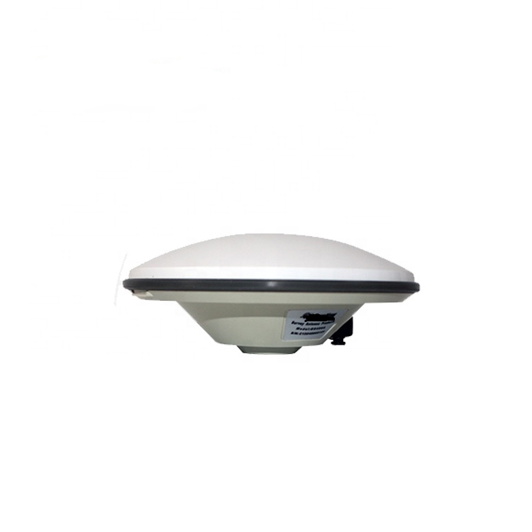
1. Radome and Housing:
The first line of defense is the external radome. This is not a simple plastic cover but a critically engineered component.
Material: It is typically injection-molded from high-grade, UV-stabilized materials such as polycarbonate, ABS, or more advanced composites. These materials are selected for their excellent RF transparency—meaning they allow GNSS frequencies to pass through with minimal attenuation and, crucially, minimal phase distortion, which is critical for accuracy. They must also possess high impact resistance to withstand flying debris and accidental knocks.
Shape: The radome shape is often aerodynamically designed (e.g., a low-profile dome or a streamlined "shark fin") to minimize wind resistance and prevent water from pooling on top. This reduces physical stress on the mounting base and avoids the signal attenuation caused by a layer of water.
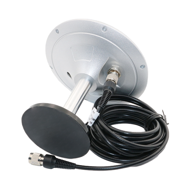
Sealing: The junction between the radome and the base is a critical seal. High-quality gaskets made from materials like silicone or EPDM rubber are used. The entire assembly is often held together with stainless steel screws and may be further sealed with marine-grade adhesive to ensure a permanent waterproof bond. The cable entry point is another critical area, typically using a strain relief and a waterproof gland or compression nut to prevent water from wicking up the cable.
2. Internal Antenna Element:
Inside the radome lies the radiating element, usually a ceramic patch antenna. The ceramic substrate has a high dielectric constant, allowing the patch to be made smaller while maintaining its resonant frequency. The patch is precisely etched to receive Right-Hand Circularly Polarized (RHCP) signals and is designed to operate across the required GNSS frequency bands (e.g., L1, L2, L5). For marine applications, the patch is mounted on a robust, non-corrosive ground plane, which is essential for shaping the antenna's radiation pattern.
3. Low-Noise Amplifier (LNA) and Filtering:
The weak signal from the patch is fed directly into a Low-Noise Amplifier (LNA). The specifications of this LNA are paramount:
Low Noise Figure (NF): Typically between 0.8 and 2.0 dB, ensuring minimal addition of electronic noise.
High Gain: Usually between 25 dB and 35 dB, to overcome downstream cable loss.
High Linearity: To resist being overloaded (saturated) by strong out-of-band signals from onboard VHF radios, radar, or satellite communication systems.
The LNA is accompanied by bandpass filters (often Surface Acoustic Wave or SAW filters) that define the operational bandwidth, allowing GNSS frequencies to pass while rejecting powerful interfering signals from other marine electronics, a common issue on a crowded boat.
4. Environmental Hardening:
Conformal Coating: The entire printed circuit board (PCB) containing the LNA and filters is often coated with a thin layer of acrylic, urethane, or silicone-based conformal coating. This protects the circuitry from corrosion caused by humidity and salt air condensation that can permeate even sealed enclosures over time.
Potting: In some high-end or extremely rugged designs, the internal cavity is potted—filled with a solid or gelatinous compound (like epoxy or polyurethane). This provides superior protection against shock, vibration, and humidity by immobilizing the components and creating a complete barrier against moisture. However, potting can make repairs impossible and must be carefully engineered to avoid affecting RF performance.
Corrosion-Resistant Metals: All metal parts—the base, mounting hardware, and connector—are made from marine-grade stainless steel (316), brass with a corrosion-resistant plating (e.g., nickel or chrome), or heavily anodized aluminum.
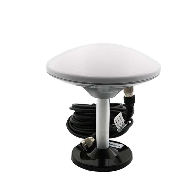
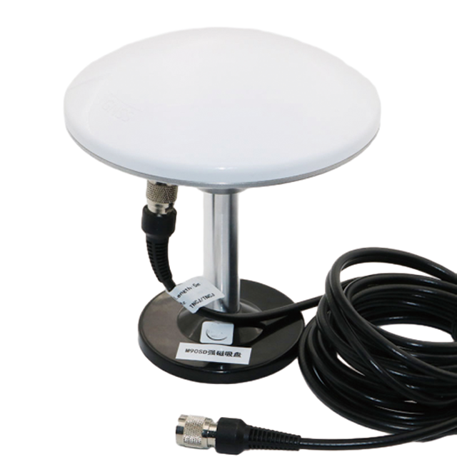
5. Cable and Connector:
The antenna is fitted with a permanent, high-quality coaxial cable. The cable itself is specially selected for low loss at GNSS frequencies and features a double-shielded construction (e.g., foil and braid) to minimize noise pickup from the vessel's engine and other electronics. The connector at the end, usually an N-type or TNC connector (known for their robust and waterproof qualities), is often pre-attached and sealed with heat-shrink tubing to ensure a waterproof connection to the receiver's cable.
The working principle of a waterproof GNSS marine antenna follows a clear signal chain focused on capture, preservation, amplification, and delivery, all while operating within a hostile RF and physical environment.
1. Signal Capture and Polarization Selection:
The process begins when electromagnetic waves from GNSS satellites, after traveling over 20,000 km, strike the antenna's radome. The radome's material allows these signals to pass through with minimal reflection or absorption. The internally mounted ceramic patch antenna is precisely dimensioned to resonate at the target frequencies (e.g., 1575.42 MHz for GPS L1). Its physical structure is designed to be most sensitive to Right-Hand Circular Polarization (RHCP), which is the polarization used by all GNSS satellites. This provides a natural first layer of discrimination against reflected signals, which often become reversed (LHCP) after bouncing off the water's surface or the vessel's superstructure—a common source of multipath error in marine environments.
2. Initial Amplification and Noise Management:
The currents induced in the patch element by the satellite signals are extraordinarily weak, often measured in picowatts. They are immediately fed into the Low-Noise Amplifier (LNA). The LNA's primary role is to boost the amplitude of these signals by a factor of hundreds or thousands (25-35 dB gain) while adding the absolute minimum amount of its own thermal noise (quantified by its low Noise Figure). This step is critical because it elevates the signal power well above the inherent thermal noise floor generated by the coaxial cable that will connect the antenna to the receiver below deck. By amplifying the signal at the source, the antenna ensures that the signal-to-noise ratio (SNR) is dominated by the high-quality LNA, not the lossy cable.
3. Interference Rejection:
The marine RF environment is notoriously noisy. A vessel may have a VHF radio, radar, satellite communications (e.g., VSAT), fish finders, and other transmitters all operating in close proximity. These devices can emit powerful out-of-band energy that could easily overload the sensitive GNSS receiver. The antenna's integrated bandpass filters act as a spectral gatekeeper, allowing only the specific frequencies used by GNSS constellations to pass through to the output. This prevents jamming or desensitization of the downstream receiver, ensuring continuous operation even when other systems are active.
4. Delivery and Cable Loss Mitigation:
The now-clean and powerfully amplified signal is presented to the output cable. The significant gain provided by the LNA is the key to overcoming cable loss. For example, a 15-meter cable might have 3 dB of loss at L1 frequency, meaning it would halve the signal power. With an antenna providing 30 dB of gain, the signal emerges from the antenna 30 dB stronger, travels through the cable losing 3 dB, and arrives at the receiver 27 dB stronger than it started. This ensures the receiver is presented with a robust, high-quality signal capable of maintaining stable phase lock—the prerequisite for accurate positioning.
5. Continuous Environmental Defense:
Throughout this entire electronic process, the antenna's physical construction is continuously defending itself. The waterproof seals prevent saltwater from causing a short circuit or corroding the delicate PCB traces. The UV-stabilized radome prevents clouding or brittleness that would attenuate the signal. The corrosion-resistant metals ensure the electrical ground remains stable and the mounting secure despite constant exposure to salt spray. The antenna doesn't just work; it actively survives to work another day.
The deployment of a purpose-built waterproof GNSS marine antenna offers significant advantages for safety and performance but also presents unique challenges that influence design, selection, and installation.
Advantages:
Unmatched Reliability and Durability: The primary advantage is supreme resilience against the marine environment. Resistance to water, salt, UV, and physical shock ensures continuous operation, which is a critical safety-of-life concern far from shore. This reliability reduces maintenance, downtime, and replacement costs.
Superior Signal Integrity in Noisy Environments: The combination of high-gain LNA and advanced filtering provides a clear signal in the electrically noisy environment of a modern vessel. This rejection of interference from onboard electronics prevents dropouts and position errors that could occur with a lesser antenna.
Mitigation of Marine-Specific Errors: The design, particularly the RHCP patch and ground plane, helps mitigate multipath error caused by signals reflecting off the highly reflective sea surface and the metal superstructure of the boat itself. This leads to a more stable and accurate position fix.
Long Cable Run Capability: The integrated amplification allows for long cable runs from the mast or flybridge to the receiver at the helm station without significant signal degradation, offering great flexibility in installation planning.
Multi-Constellation Support: Most marine antennas are designed to receive all major GNSS systems, providing redundancy and increased satellite coverage. This is crucial for maintaining a position fix in challenging conditions, such as when in a steep-sided waterway or when some satellites are blocked by the vessel's structure.
Challenges:
Cost: The use of specialized materials (e.g., 316 stainless steel, high-quality coaxial cable), rigorous manufacturing processes, and environmental testing makes waterproof marine antennas significantly more expensive than their land-based counterparts.
Complexity of Installation: While designed for durability, proper installation is critical. Achieving a waterproof seal through the deck or on a rail requires careful work with sealants (e.g., butyl tape, polysulfide) to prevent deck core leaks, which can cause serious damage to the vessel. Poor installation is a common point of failure.
Weight and Size: The robust construction can result in a heavier and larger antenna. This must be considered when mounting on a thin mast or a rail where excessive weight and windage could be an issue.
Potential for Internal Corrosion: Despite sealing, over many years, humidity can eventually permeate the enclosure. If the internal components are not protected by conformal coating or potting, this can lead to gradual corrosion and failure of the LNA, a failure mode that is often difficult to diagnose.
Performance Trade-offs: Some ultra-low-profile "shark fin" designs may sacrifice a degree of performance for their sleek form factor. Their smaller ground plane can result in a less ideal radiation pattern, potentially making them slightly more susceptible to low-elevation multipath compared to a larger, dome-style antenna.
Waterproof GNSS marine antennas are fundamental to a vast array of applications on the water, from recreational boating to critical scientific and military operations. Their role is evolving with new technologies.
Applications:
Recreational Navigation: The largest application area. Integrated into chart plotters, multifunction displays (MFDs), and autopilots on yachts, sailboats, and powerboats to provide essential position, speed, and course-over-ground data for safe navigation.
Commercial Shipping: Used on container ships, tankers, and freighters for ocean navigation, port maneuvering, and as a primary position source for the Automatic Identification System (AIS), which is mandatory for large vessels to aid in collision avoidance.
Fishing Fleet: Critical for commercial fishing vessels for navigation to fishing grounds, track plotting, and as an integrated sensor in sophisticated fishery management systems. The antenna's durability is key in this harsh working environment.
Search and Rescue (SAR) and Law Enforcement: Coast Guard and police boats rely on highly accurate and reliable GNSS for coordinating operations, tracking vessels, and ensuring their own safety in all weather conditions.
Hydrographic and Scientific Survey: Specialized survey vessels use high-precision GNSS antennas (often capable of RTK or PPK) to accurately map the seafloor, conduct oceanographic research, and monitor underwater infrastructure. These antennas require exceptional phase stability.
Military Naval Operations: Warships and patrol boats use hardened, and often encrypted or anti-jam, GNSS systems for navigation, weapon systems guidance, and force coordination.
Unmanned Surface Vessels (USVs): The growing field of autonomous boats for survey, environmental monitoring, and defense relies entirely on the continuous and trustworthy data from a robust marine antenna for guidance and control.
Future Trends:
Integration with Other Services: Future antennas will be "multi-service" units, combining GNSS reception with satellite communication links (e.g., Iridium, Starlink) and/or cellular modems in a single, ruggedized housing to simplify vessel topside installations.
Advanced Anti-Jamming and Spoofing Protection: As reliance on GNSS grows, so do threats. Future marine antennas will increasingly incorporate ** Controlled Reception Pattern Antenna (CRPA)** technology, which can electronically nullify interfering signals, protecting against both accidental jamming and intentional spoofing attacks.
Enhanced Multi-Band and Multi-Constellation Support: Support for all modernized signals (e.g., GPS L5, Galileo E5) will become standard, enabling faster and more reliable high-accuracy positioning for applications like automated dockings.
Improved Materials and Miniaturization: Advances in composite materials and electronics will lead to lighter, smaller, and even more durable antennas without compromising performance, benefiting smaller vessels and USVs.
AI-Driven Performance Optimization: Antennas or the connected receivers could use machine learning algorithms to dynamically characterize and filter multipath specific to the vessel's superstructure, further refining position accuracy in real-time.
Conclusion
The waterproof GNSS marine antenna is a paragon of specialized engineering, a device where form and function are perfectly tailored to conquer a specific set of extreme challenges. It is far more than a simple receiver; it is a hardened sensor, a first-line amplifier, and a filter, all encased in a environmental vault. Its value is not measured merely in its ability to receive signals, but in its unwavering capacity to do so day after day, in conditions of salt, sun, storm, and spray that systematically destroy lesser equipment.
Its role is foundational to modern marine electronics, feeding pristine data to the navigation suite that forms the central nervous system of any vessel, from the smallest weekend sailboat to the largest container ship. The advantages it provides—reliability, signal integrity, and interference rejection—are direct enablers of safety, efficiency, and operational capability on the water. While challenges of cost and installation complexity exist, they are far outweighed by the critical need for dependable positioning.
Looking forward, the evolution of the marine antenna is clear. It will become smarter, more integrated, and more resilient, evolving from a passive receiver into an intelligent node in a broader maritime network. As autonomous vessels and advanced naval systems become more prevalent, the demand for these robust, high-performance antennas will only intensify. They will remain, quite literally, the highest point of contact between the vessel and the outside world, the silent, steadfast guarantor of a safe and known position on the vast and unforgiving sea.

 86 0755 2819 9597
Lucy Yang | lucy.y@toxutech.com
Nicole Li | nicole@toxutech.com
Dotty Zhao | sales04@toxutech.com
Global Business Director / Sales Team / Global Operations


 En
En Cn
Cn Korean
 Home >


