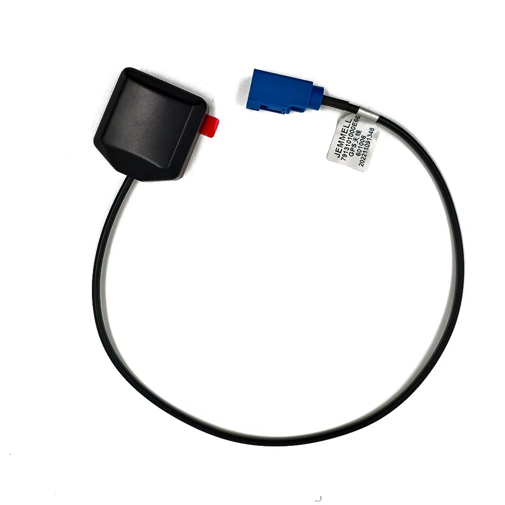
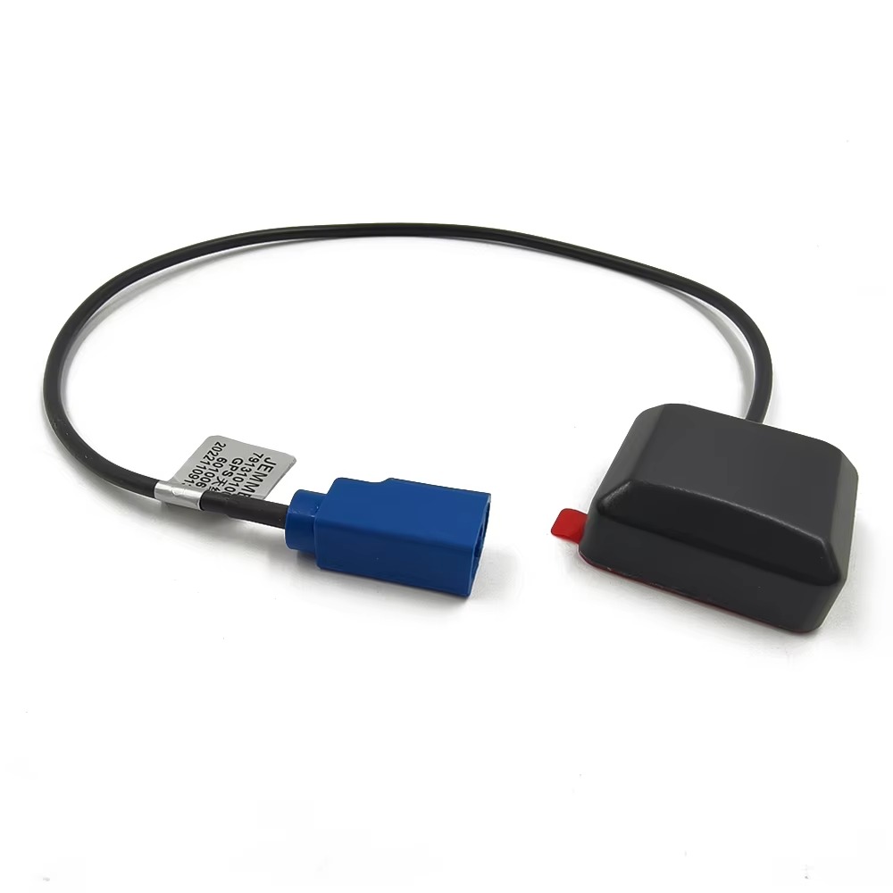
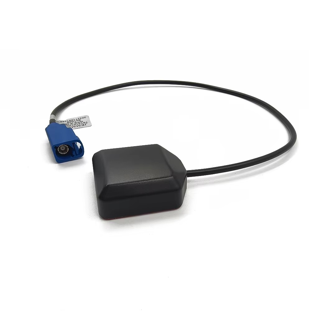
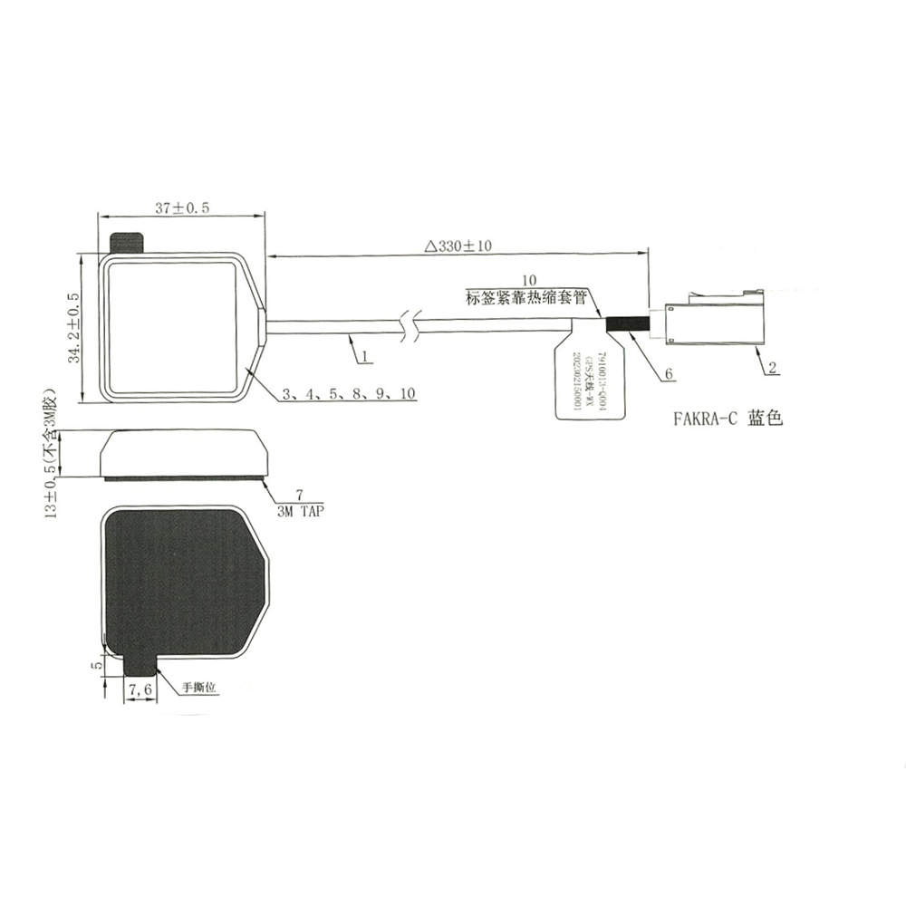
In the vast ecosystem of Global Positioning System (GPS) technology, where precision often demands permanent and complex installation, the strong-magnet magnetic mount GPS antenna stands as a paradigm of convenience, versatility, and rapid deployment. This antenna is a specialized solution designed for a world in mobility, providing a reliable and high-performance GPS signal for applications where drilling holes, running cables through panels, or committing to a fixed location is either impractical, undesirable, or prohibited. It is the go-to choice for temporary setups, fleet vehicles, rental equipment, and any scenario where operational flexibility is paramount.
A strong-magnet magnetic mount GPS antenna is an active antenna system that integrates three key components into a single, cohesive unit: a high-performance GPS antenna element, a built-in Low-Noise Amplifier (LNA), and a powerful permanent magnet base, often encased in a durable, weather-resistant housing. The term "strong-magnet" is the defining characteristic; it typically refers to a neodymium magnet (also known as a rare-earth magnet), which possesses an exceptionally powerful magnetic force relative to its size. This allows the antenna to form a secure, semi-permanent bond with any ferromagnetic surface—primarily the steel roofs and body panels of vehicles—with nothing more than the magnetic force itself.
The primary role of this antenna is to solve the pervasive challenge of signal attenuation caused by a vehicle's body. GPS signals, particularly the L1 frequency at 1575.42 MHz, are effectively blocked by metal. Placing a GPS receiver inside a vehicle, whether it's a dashboard-mounted navigator, a telematics unit, or a smartphone, severely degrades its ability to "see" the satellites. The magnetic mount antenna elegantly bypasses this problem. By being placed on the vehicle's exterior roof or trunk lid, it is granted an completely unobstructed view of the sky. It then captures the faint satellite signals, amplifies them internally, and delivers a strong, clean signal via a coaxial cable that is routed through a door or window seal to the receiver inside the cabin.
The applications for this device are remarkably broad. It is the standard for law enforcement vehicles, where officers need reliable GPS tracking and mapping without permanent vehicle modification. It is indispensable for fleet management, allowing companies to easily equip and re-equip trucks and vans with tracking devices. It is used by surveyors and GIS professionals for temporary mapping projects, by journalists and field reporters for timestamping and location data, and by everyday consumers seeking to boost the GPS performance of their personal navigation devices or smartphones in a rental car.
The design philosophy of the magnetic mount antenna is one of utilitarian robustness. It must not only perform well electromagnetically but also withstand the rigors of the mobile environment. This includes resisting UV radiation from the sun, precipitation, extreme temperatures, and, most critically, the immense wind forces and vibrations encountered at highway speeds. The magnet must be strong enough to resist sliding or becoming dislodged, while the cable and its entry point into the antenna must be engineered to withstand constant flexing and strain.
In essence, the strong-magnet magnetic mount GPS antenna is a masterpiece of practical engineering. It represents a perfect marriage of electromagnetic theory and mechanical design, offering a "quick-fix" that does not compromise on performance. It is the ultimate tool for establishing a high-quality GPS connection in minutes, providing the crucial link between the mobile user and the constellation of satellites overhead, ensuring that no matter where the mission goes, accurate positioning data is always securely attached and readily available.
The design and construction of a strong-magnet magnetic mount GPS antenna is a focused exercise in creating a robust, self-contained system that balances powerful adhesion with high-frequency electronic performance. Every component, from the magnet to the radome, is selected and assembled to ensure reliable operation in a demanding mobile environment.
1. The Magnetic Assembly: The Foundation of Mounting
The heart of the mount is the magnet itself. This is not a simple ferrite magnet but almost invariably a neodymium magnet (NdFeB). Neodymium magnets are chosen for their extraordinary magnetic strength, offering the highest magnetic energy product of any commercially available material. This allows for a relatively compact magnet to generate a holding force sufficient to withstand high wind speeds, vibrations, and sudden vehicle movements without shifting. The magnet is typically a thick disc or a series of smaller magnets arranged in a pattern to maximize surface contact and pulling force. It is almost always plated or coated (e.g., with nickel) to protect the brittle neodymium material from chipping and corrosion.
This magnet is housed within a protective cup or base, usually made from durable, corrosion-resistant materials like powder-coated steel or stainless steel. This base serves multiple purposes: it protects the magnet, provides a smooth, finished surface that will not scratch the vehicle's paint (often lined with a soft felt or rubber layer), and acts as the ground plane for the antenna element.
2. The Antenna Element: The GPS Sensor
Mounted directly onto or above the magnetic base is the antenna's radiating element. The most common type is a ceramic patch antenna. A square of ceramic material with a high dielectric constant is used, allowing the patch to be made electrically small to resonate at the GPS L1 frequency while maintaining a low physical profile. The patch itself is typically metallized onto the ceramic and is designed to receive Right-Hand Circularly Polarized (RHCP) signals. The metal base of the mount itself acts as the ground plane for this patch, critically shaping its radiation pattern to be directional towards the sky and providing inherent rejection of signals arriving from below the horizon (multipath).
3. The Low-Noise Amplifier (LNA): The Signal Booster
The antenna is an "active" design, meaning it contains an integrated LNA on a small printed circuit board (PCB) within the housing. This is absolutely essential for this application. The LNA's functions are:
Gain: It provides high amplification (typically 25-35 dB) to boost the incredibly weak satellite signals.
Overcoming Cable Loss: This gain ensures the signal is strong enough to travel through the long coaxial cable (often 3-5 meters) to the receiver inside the vehicle without being degraded below the receiver's sensitivity threshold.
Low Noise Figure: The LNA is designed to add minimal self-generated noise (a noise figure of <2 dB is common), preserving the crucial signal-to-noise ratio (SNR).
4. The Housing and Radome: Environmental Protection
The entire electronic assembly is encapsulated within a protective housing. The top of this housing is the radome—a dome-shaped cover made from RF-transparent material. This is typically a high-grade plastic like ABS or polycarbonate that is UV-stabilized to prevent yellowing and weakening from prolonged sun exposure. The radome must be designed to have minimal impact on the signal passing through it. The entire housing is sealed, often to an IP67 rating, making it waterproof and dustproof to protect the internal electronics from rain, snow, and car wash spray.
5. The Cable and Strain Relief
A coaxial cable is permanently attached to the antenna assembly. This is a critical and often vulnerable component.
Cable Type: A high-quality, thin-diameter coaxial cable like RG-174 is often used for its flexibility, making it easy to route through car door seals.
Connector: The other end is terminated with a connector, most commonly SMA or TNC, to plug into the GPS receiver.
Strain Relief: The point where the cable exits the antenna housing is a major point of mechanical failure. A critical design feature is a robust strain relief—a reinforced rubber boot or molded section that absorbs bending forces and prevents the cable from being pulled loose from the internal solder joints, which would break the electrical connection and render the antenna useless.
6. Integration and Sealing
The final assembly involves potting or sealing the internal electronics with a waterproof epoxy or silicone compound. This secures the PCB and cable connections, provides resistance to vibration and shock, and protects against humidity and thermal cycling that could cause condensation inside the unit.
The construction of a magnetic mount antenna is thus a process of creating a resilient, self-contained system. It must be electromagnetically efficient to receive weak signals, mechanically tough to stay attached to a speeding vehicle, and environmentally sealed to survive years of exposure to the elements. The strong magnet is the enabling feature, but the quality of the entire integrated system determines its performance and longevity.
The operation of a strong-magnet magnetic mount GPS antenna is a streamlined process of signal acquisition, amplification, and delivery, engineered specifically to overcome the inherent limitations of in-vehicle GPS reception. Its working principle can be broken down into a sequence of stages that transform a faint whisper from space into a robust digital signal for a receiver.
1. Overcoming the Faraday Cage Effect
The fundamental problem this antenna solves is the Faraday cage effect. A vehicle's body, made of steel or aluminum, acts as a shield that attenuates electromagnetic waves, including GPS signals. A GPS receiver placed inside the cabin receives only severely weakened and multipath-distorted signals that manage to diffract through the windows. This results in poor satellite acquisition, low accuracy, and frequent signal dropouts. The magnetic mount antenna bypasses this entirely by being placed on the vehicle's exterior, where it has a completely unobstructed, 360-degree view of the sky, free from the signal-blocking effects of the vehicle's metal structure.
2. Signal Capture and Ground Plane Coupling
The antenna element, typically a ceramic patch, is designed to resonate at the GPS L1 frequency of 1575.42 MHz. It is optimized to receive Right-Hand Circularly Polarized (RHCP) signals, which are used by GPS satellites to mitigate signal degradation caused by atmospheric conditions and reflections. The metal roof of the vehicle, to which the antenna is magnetically attached, is not just a mounting platform; it becomes an integral part of the antenna system. It functions as the ground plane. A proper ground plane is essential for a patch antenna as it:
Directs the radiation pattern upward, maximizing gain towards the satellites and minimizing sensitivity towards the horizon.
Provides a stable electrical reference point for the radiating element.
Enhances the antenna's efficiency and helps to reject multipath signals reflected from the ground or the vehicle's own surfaces.
The strength of the magnet is crucial here. It ensures intimate electrical contact between the antenna's base and the vehicle's body, creating a unified RF ground. A weak magnet or a dirty surface could create a poor ground connection, degrading performance.
3. Low-Noise Amplification: The First and Critical Boost
The signals captured by the patch element are incredibly weak, often below -130 dBm. Before these signals can be sent anywhere, they must be amplified. This is the job of the integrated Low-Noise Amplifier (LNA), located immediately after the radiating element inside the antenna housing. The LNA performs two vital functions:
Amplification: It provides high gain (e.g., 30 dB), boosting the signal strength by a factor of 1000.
Noise Management: Its low noise figure ensures it adds almost no self-generated thermal noise to the signal. This is critical because amplifying a signal along with a lot of noise would simply create a louder, but still noisy, useless signal. By amplifying the signal with minimal added noise at the very source, the LNA "locks in" a high Signal-to-Noise Ratio (SNR).
4. Signal Transmission and Delivery
The now-amplified signal is sent down the attached coaxial cable. The high gain from the LNA is specifically calculated to overcome the attenuation (signal loss) that occurs within this cable. Without this pre-amplification, the signal would be too weak by the time it reached the receiver after several meters of cable loss. The cable is routed through a door or window seal into the vehicle's interior and connected directly to the GPS receiver's antenna input port.
5. Receiver Processing
The GPS receiver inside the vehicle receives a strong, clean signal. It then performs the complex tasks of demodulation, correlation, and navigation solution calculation. Because the input signal is strong and has a high SNR, the receiver can:
Acquire satellites more quickly.
Maintain a stable lock on more satellites.
Calculate a more accurate and reliable position, velocity, and time (PVT) solution.
In summary, the working principle of the magnetic mount antenna is one of strategic positioning and intelligent signal conditioning. It physically places the sensor in the optimal location, uses the vehicle itself to enhance its performance, amplifies the signal at the point of capture to preserve its quality, and delivers a robust data stream to the receiver, ensuring that the vehicle's navigation and tracking systems always have the best possible data to work with.
The strong-magnet magnetic mount GPS antenna offers a compelling set of advantages that have made it a ubiquitous tool in mobile communications. However, this specific design also introduces a unique set of challenges and limitations that users must understand to ensure optimal performance and avoid potential pitfalls.
Advantages
Unmatched Deployment Speed and Flexibility: This is the paramount advantage. The antenna can be deployed or relocated in seconds. There is no need for drilling, adhesives, or specialized tools. This makes it ideal for temporary installations, rental vehicles, fleet management where vehicles are frequently swapped, or situations where drilling into a vehicle is not permitted (e.g., leased vehicles, law enforcement undercover cars).
Superior Signal Performance Over Internal Antennas: By being located outside the vehicle, the antenna completely bypasses the signal-blocking Faraday cage effect of the metal body. It provides a clear, unobstructed view of the sky, leading to faster satellite acquisition, tracking of more satellites, and a overall more accurate and reliable position solution compared to any internal antenna.
Integrated Ground Plane: The vehicle's metal roof or body panel acts as an excellent ground plane for the antenna. This enhances the antenna's efficiency, improves its gain pattern (directing energy upward), and provides inherent rejection of low-angle multipath signals reflected from the road surface. The strong magnet ensures a solid electrical connection to this ground plane.
Cost-Effectiveness and Convenience: For the performance gain it offers, it is a relatively low-cost solution. It eliminates the time and labor costs associated with a permanent installation, making it highly economical for large fleets or temporary projects.
Portability and Reusability: A single antenna can be used on multiple vehicles sequentially. A surveyor, technician, or journalist can carry one antenna and use it on whatever vehicle they are assigned to for the day, making it a highly versatile and reusable asset.
Robustness for Mobile Use: Well-designed models are built to withstand the environment. They are waterproof, UV-resistant, and designed to handle the vibration and wind forces encountered at highway speeds.
Challenges and Limitations
Security and Theft Vulnerability: The very feature that enables its easy deployment also makes it easy to steal. A valuable antenna sitting on a roof is a target for theft in public parking areas. Users must be vigilant about removing it when the vehicle is unattended.
Potential for Paint Damage: Despite protective felt or rubber layers, the magnet can still trap abrasive dirt and moisture against the vehicle's paint. Over time, especially if the antenna is frequently moved while dirty, this can lead to swirl marks or scratches. In some cases, very strong magnets might cause slight dimpling on thinner metal panels.
Cable Management and Aesthetics: The coaxial cable must be routed into the vehicle, typically through a door or window seal. This can be awkward, can slightly compromise the seal (potentially allowing noise or moisture ingress), and leaves a visible cable running into the cabin, which some users find untidy.
Dependence on a Ferromagnetic Surface: The antenna is useless on vehicles with non-ferromagnetic bodies, such as those made from aluminum, carbon fiber, or fiberglass. For these vehicles, an alternative mounting solution (e.g., adhesive mount) is required.
Mechanical Strain on the Cable: The cable exit point is a common failure point. If the cable is snagged or the antenna is moved by pulling on the cable (instead of the body), it can break the internal solder joints or damage the strain relief, resulting in an intermittent or complete failure.
Inconsistent Ground Plane: While a vehicle roof is an excellent ground plane, its electrical properties are not perfectly controlled. The size and shape of the roof can slightly affect the antenna's performance characteristics (like its resonant frequency and radiation pattern) compared to its performance on a standardized test platform. This is usually a minor effect but is a consideration for ultra-high-precision applications.
In conclusion, the advantages of the magnetic mount antenna are overwhelmingly centered on convenience, performance, and flexibility. The challenges are primarily practical and logistical: security, care for the vehicle's finish, and cable management. For the vast majority of mobile applications where permanent installation is not desired, the benefits far outweigh the drawbacks, making it an enduringly popular and effective solution.
The strong-magnet magnetic mount GPS antenna is a workhorse component whose simplicity and effectiveness have secured its role in a diverse range of mobile and portable applications. It is the enabling technology for rapid GPS deployment across numerous industries. Furthermore, its design continues to evolve to meet new demands and integrate with emerging technologies.
Applications
Fleet Management and Telematics: This is one of the largest applications. Companies use these antennas to easily equip their trucks, vans, and cars with GPS tracking devices for logistics optimization, driver behavior monitoring, fuel efficiency analysis, and asset security. The magnetic mount allows for quick installation and transfer between vehicles, maximizing flexibility for growing or changing fleets.
Law Enforcement and Public Safety: Police, ambulance, and fire services use these antennas on patrol cars and incident response vehicles. They provide reliable location data for computer-aided dispatch (CAD) systems, automatic vehicle location (AVL), and mobile data terminals. The temporary nature of the mount is ideal for unmarked or pooled vehicles.
Field Service and Utilities: Technicians working in fields like telecommunications, oil and gas, and electricity distribution use these antennas with ruggedized tablets or laptops for GIS data collection, asset mapping, and navigating to remote job sites. The antenna can be quickly placed on a service truck at the start of a shift.
Journalism and Live Broadcasting: News vans and field reporters use magnetic mount antennas to provide precise location and timing data for satellite uplinks, live feeds, and timestamping field reports. They are also used with satellite phones for communication from remote locations.
Consumer and Recreational Use: Individuals use them to boost the GPS signal for personal navigation devices in rental cars, for in-car gaming systems that use location data, or with portable GPS units for road trips and camping. They are also popular in the RV and boating communities as a temporary solution when a permanent antenna is not installed.
Temporary Surveying and Mapping: While not for high-precision RTK work, these antennas are perfectly suitable for lower-accuracy GIS data collection, environmental monitoring, and mapping applications where a quick, temporary setup is required.
Future Trends
Integration of Multi-Band and Multi-Constellation Support: The next generation of magnetic mount antennas will move beyond GPS L1. Multi-band antennas that also receive L5, L2, and signals from all major constellations (GLONASS, Galileo, BeiDou) will become standard. This will provide faster acquisition, better accuracy, and improved reliability in urban canyons, even for consumer-grade applications.
Development for Non-Ferrous Surfaces: To address the limitation of aluminum and composite-bodied vehicles, future designs may incorporate hybrid mounting systems. This could involve a magnetic base paired with a strong supplemental adhesive for non-ferrous surfaces, or the development of more powerful and cleverly designed magnets that can work with thinner aluminum panels.
"Smart" Antennas with Integrated Electronics: The antenna could evolve into a more intelligent device. Future models might incorporate a small GNSS receiver chip within the housing itself, outputting position data via a digital protocol like USB or Bluetooth. This would turn the antenna into a complete, self-contained GPS sensor, reducing cable clutter and allowing it to connect directly to tablets and smartphones without a separate receiver unit.
Enhanced Durability and Materials: The use of more advanced polymers and composites will make radomes even more resistant to UV degradation and physical impact. Strain relief technology will continue to improve to virtually eliminate cable breakage, the most common point of failure.
Miniaturization and Lower Profile: Advances in ceramic patch technology and electronics will allow for high-performance antennas in an even smaller and lower-profile form factor. This would reduce wind resistance, improve aesthetics, and make them less obtrusive on vehicle roofs.
Focus on Cybersecurity: As GNSS jamming and spoofing become more prevalent, there may be a demand for magnetic mount antennas that incorporate basic filtering to reject out-of-band interference, providing a first layer of defense for the connected receiver.
The strong-magnet magnetic mount GPS antenna is not a static technology. It will continue to adapt, offering greater performance, intelligence, and versatility. Its core value proposition—instantaneous deployment and reliable external signal acquisition—will ensure it remains a vital tool in the mobile connectivity toolkit for years to come, finding new applications in the evolving landscapes of autonomous logistics, connected cars, and the Internet of Things.
Conclusion
The strong-magnet magnetic mount GPS antenna is a quintessential example of elegant and practical engineering solving a well-defined problem. It stands as a testament to the principle that the most effective solutions are often those that are simple to deploy, intuitive to use, and directly address a core user need. In a world increasingly dependent on precise location data, this antenna democratizes high-performance GPS reception, making it accessible to anyone with a vehicle, without the need for commitment, expertise, or permanent modification.
Its design is a successful fusion of disparate disciplines. It combines the brute force of neodymium magnet chemistry with the subtle finesse of RF microwave engineering. The antenna element itself is a masterpiece of miniaturization, leveraging the properties of high-dielectric ceramics to create a resonant structure that fits in the palm of your hand. The integration of the low-noise amplifier showcases an understanding of the entire signal chain, amplifying the signal at the optimal point to overcome the inevitable losses of a practical installation. And all of this is packaged within a housing that must be both environmentally sealed and aesthetically unobtrusive.
The advantages it offers are profound in their practicality. The ability to achieve a near-permanent level of mounting security in a matter of seconds is its killer feature. This unlocks unparalleled flexibility for fleet managers, field technicians, and public safety officials. The dramatic improvement in signal quality over any in-vehicle solution provides tangible benefits in accuracy, reliability, and operational efficiency. It is a tool that pays for itself not through complexity, but through sheer utility and time saved.
While it is not without its limitations—the need for a ferrous surface, the vulnerability to theft, and the minor hassle of cable routing—these are not design flaws but rather the inherent trade-offs of its chosen form factor. They are well-understood constraints that users can easily manage and mitigate.
Looking forward, the magnetic mount antenna is far from obsolete. It is a platform ripe for evolution. The integration of multi-band, multi-constellation reception will future-proof it against the ongoing modernization of GNSS. Its role may expand as it becomes a simpler plug-and-play digital sensor for the growing ecosystem of mobile IoT devices and connected car applications.
In conclusion, the strong-magnet magnetic mount GPS antenna is a classic. It is a perfect solution for a specific, widespread need. It embodies the idea that technology should adapt to the user's environment and workflow, not the other way around. It proves that a product doesn't need to be overly complex to be extremely powerful. By providing a robust, high-performance, and instantly deployable window to the satellites, it has secured its place as an indispensable tool for mobile professionals and everyday users alike, ensuring that reliable positioning is always just a quick, magnetic snap away.
18665803017 (Macro)