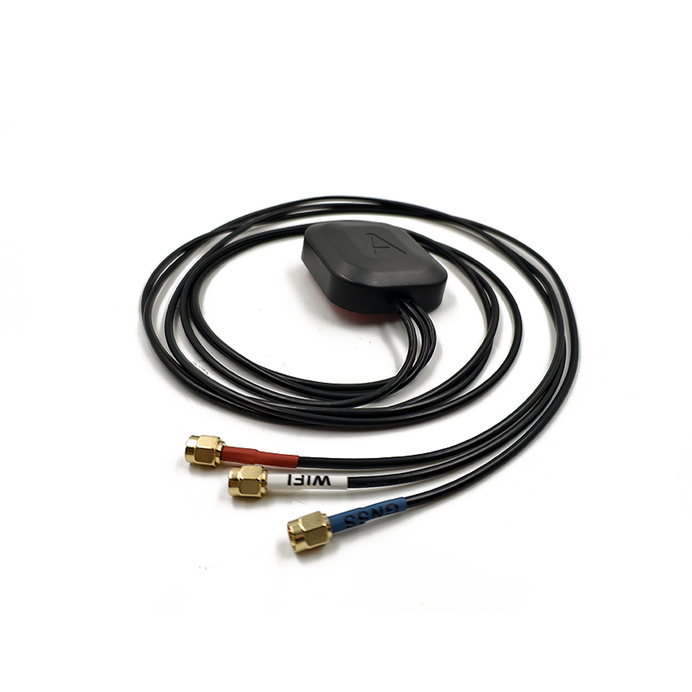
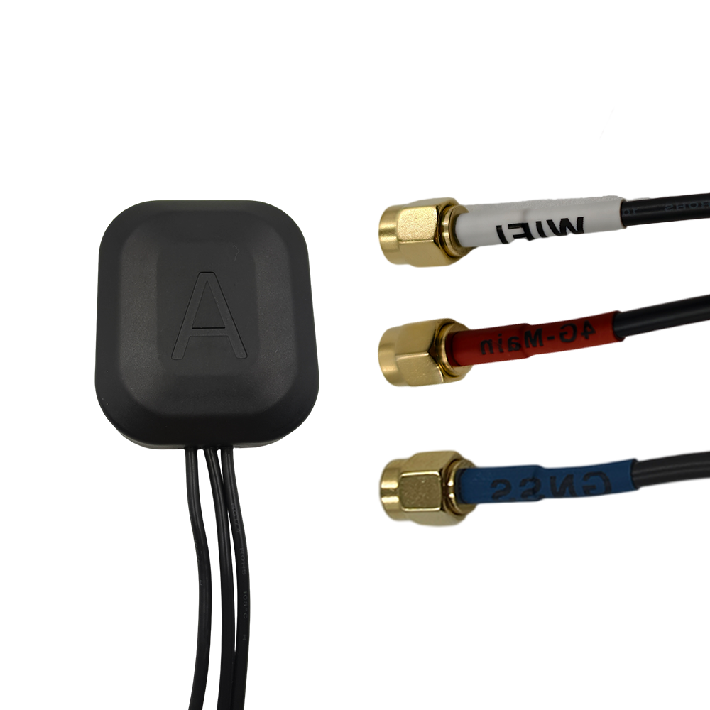
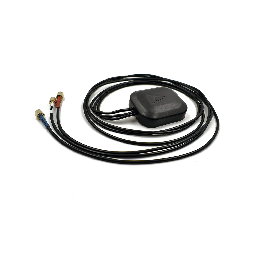
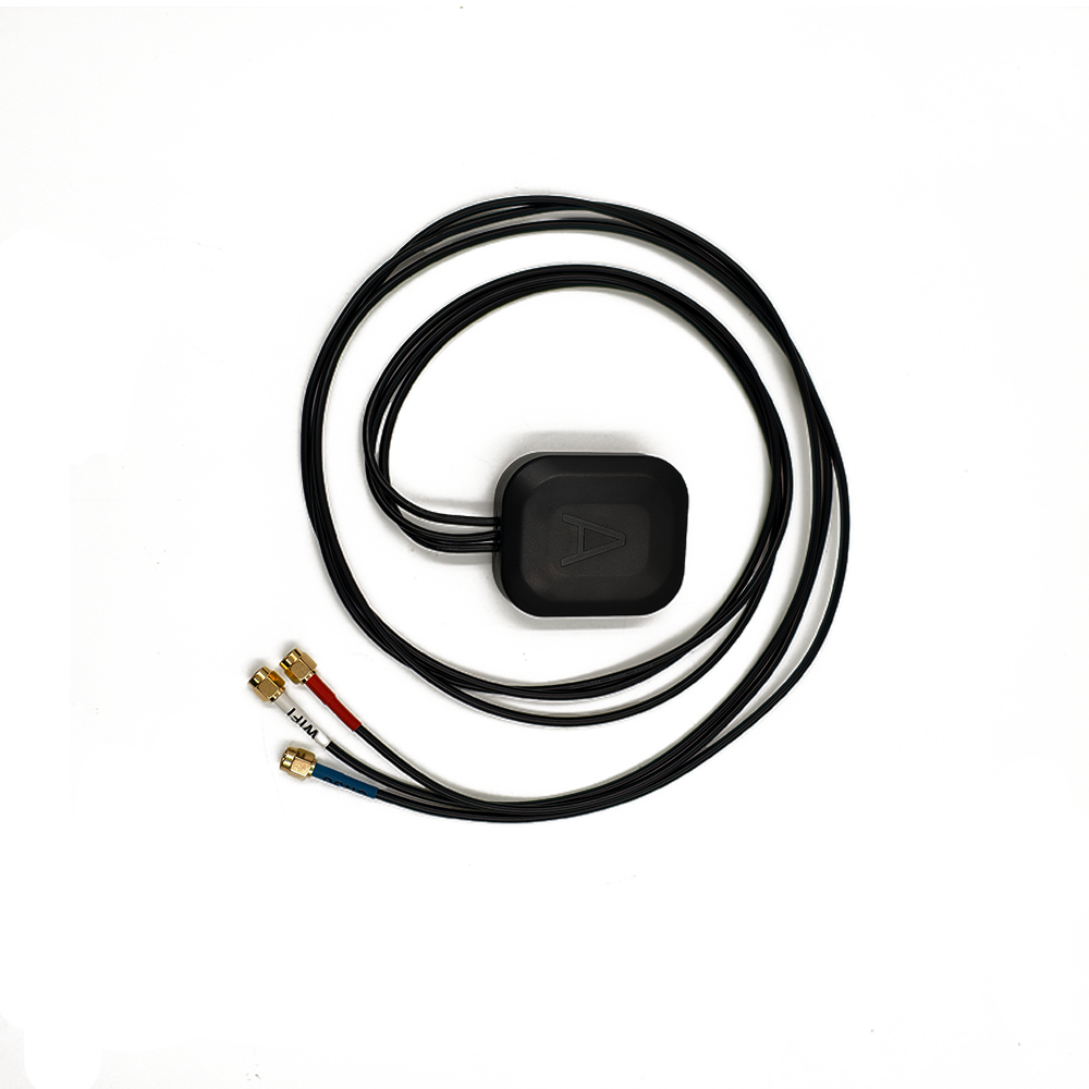
overview
A Small-Sized Multi-Band RTK Ceramic Antenna is a type of passive antenna defined by its key characteristics:
Small-Sized: Typically measuring between 10x10mm to 25x25mm, with a height of just 3-6mm, this antenna is designed for integration into space-constrained devices. This miniaturization is a radical departure from the large, bulky choke-ring antennas traditionally associated with high-precision GNSS.
Multi-Band: It is engineered to receive signals from multiple frequency bands across all major Global Navigation Satellite Systems (GNSS), including GPS (L1, L2, L5), GLONASS (L1, L2, L3), Galileo (E1, E5a, E5b, E6), and BeiDou (B1, B2, B3). This capability is fundamental to modern RTK, which uses multi-frequency observations to quickly resolve integer ambiguities and correct for ionospheric delay.
RTK: This designation signifies that the antenna is designed to meet the stringent requirements of carrier-phase-based positioning. Unlike standard navigation antennas, an RTK-grade antenna must exhibit exceptional phase center stability and provide effective multipath mitigation, even within its tiny footprint.
Ceramic: The antenna's core is a block of ceramic material with a very high dielectric constant (εr). This property is the key to miniaturization, as it allows the antenna to be electrically large (resonant at GNSS frequencies) while being physically small.
The proliferation of this technology is fueled by the explosion of portable and autonomous systems requiring high-precision location. Applications such as drone-based surveying, handheld mapping devices, wearable technology for sports analytics, autonomous robotics, and compact asset trackers cannot accommodate traditional survey-grade antennas. They demand a solution that is lightweight, low-profile, and capable of being embedded directly onto a product's main printed circuit board (PCB), yet still delivers the performance needed for reliable RTK fixes.
However, this miniaturization presents a profound engineering challenge. The laws of physics dictate a fundamental trade-off between antenna size, bandwidth, and efficiency. Designing a tiny antenna that can operate efficiently across multiple widely-separated frequency bands (e.g., GPS L2 at 1227 MHz and GPS L1 at 1575 MHz) while maintaining a stable phase center and providing some level of multipath rejection is an immense undertaking. Furthermore, the performance of such an antenna is intrinsically linked to its integration environment—the PCB it is mounted on becomes a part of the antenna system itself.
Therefore, the small-sized multi-band RTK ceramic antenna is a testament to innovation in electromagnetic design and materials science. It is not merely a smaller antenna; it is a system-level solution that brings high-precision capabilities to a new generation of compact and mobile platforms, democratizing access to centimeter-level accuracy.
Design and Construction
The design and construction of a small-sized multi-band RTK ceramic antenna is a sophisticated balancing act, pushing the boundaries of materials science and electromagnetic theory to achieve wideband performance and stability in a minuscule package. Every layer and material is meticulously optimized for electrical performance within brutal physical constraints.
1. The High-Dielectric Ceramic Core: The Foundation of Miniaturization
The heart of the antenna is a sintered ceramic block, typically composed of a titanium-based compound (e.g., Barium Strontium Titanate). The critical property of this ceramic is its very high dielectric constant (εr or Dk), often ranging from 40 to over 90. A high Dk is the fundamental enabler of miniaturization. The physical length required for an antenna to resonate at a specific frequency is inversely proportional to the square root of the Dk (λ = λ₀ / √εr). By using an ultra-high-Dk material, the wavelength within the ceramic is dramatically shortened, allowing the physical antenna size to be reduced to a small fraction of the free-space wavelength (e.g., ~19 cm for a ¼ wave at L1), resulting in a component that can be smaller than a fingernail.
2. The Multi-Resonant Radiating Element: A Symphony of Patches
The radiating element is a precision-patterned electrode, usually silver, printed onto the ceramic surface. To achieve multi-band operation, a simple single patch is insufficient. The most common advanced design is a stacked-patch or coupled-patch configuration.
Stacked-Patch Design: This involves two or more ceramic layers, each with a patch of a different size. A larger patch is tuned to a lower frequency band (e.g., GPS L2 at 1227 MHz), while a smaller patch on a layer above is tuned to a higher frequency band (e.g., GPS L1 at 1575 MHz). The patches are electromagnetically coupled, allowing a single feed point to excite resonances across multiple bands.
Coupled-Feed Design: A single patch is used, but it is fed by a more complex network of coupling elements that excite multiple resonant modes within the same patch structure, effectively making it resonant at several frequencies.
The shape, size, and alignment of these patches are fine-tuned using 3D electromagnetic simulation software to achieve optimal performance across all target bands.
3. The Critical Role of the PCB Ground Plane
A small ceramic antenna is not a standalone component. It is designed to function in concert with the PCB's ground plane, which becomes an integral and active part of the radiating structure. The currents on the ceramic element induce mirror currents on the ground plane, which itself radiates. The size, shape, and integrity of this ground plane are paramount. Manufacturers specify a minimum required ground plane area (e.g., 40x40mm or 70x25mm) that must be kept clear of components and signals. An undersized or poorly designed ground plane is the most common cause of performance failure, as it detunes the antenna's carefully designed resonances.
4. Phase Center Stability for RTK
For RTK functionality, the stability of the antenna's Phase Center is non-negotiable. This is the biggest challenge in miniaturization.
Design Symmetry: The antenna is designed to be as electromagnetically symmetrical as possible to minimize Phase Center Variation (PCV)—the movement of the phase center with satellite elevation and azimuth.
Calibration: Despite its small size, each antenna model is rigorously calibrated in an anechoic chamber. This process maps the precise Phase Center Offset (PCO) and PCV for every supported frequency band. This calibration data is essential and must be applied in the receiver's processing software to correct measurements to a known, stable point.
5. Multipath Mitigation in a Small Package
Without the space for choke rings, small antennas rely on other techniques:
Polarization Purity: The patch is designed for perfect Right-Hand Circular Polarization (RHCP) to reject Left-Hand Circularly Polarized (LHCP) reflected signals.
Controlled Radiation Pattern: The antenna and ground plane are co-designed to shape a radiation pattern that maximizes gain towards the zenith and minimizes gain at low elevations where multipath originates.
High-Quality Materials: Using ceramic with a low loss tangent ensures that more energy is radiated rather than absorbed as heat, improving efficiency and effectively providing a stronger desired signal compared to multipath noise.
6. Construction and Assembly
The finalized multi-layer ceramic design is packaged as a standard Surface-Mount Device (SMD). The solder pads are designed to create a small air gap between the antenna body and the PCB after reflow soldering. This air gap is a critical part of the designed operating environment. The entire component is taped and reeled for fully automated pick-and-place assembly, making it ideal for high-volume production.
In summary, the construction of this antenna is a holistic process of creating a "performance engine" that is intentionally incomplete. Its final characteristics are a product of its own sophisticated design and the host device's PCB, demanding careful co-design between the antenna manufacturer and the product engineer.
Working Principles
The operation of a small-sized multi-band RTK ceramic antenna is a delicate and intricate process of resonant energy capture, frequency separation, and environmental interaction. Its task is to perform with a level of fidelity associated with much larger antennas, all from a tiny portal on a circuit board.
1. Multi-Band Resonance: Tuning to Multiple Frequencies
The core of its functionality is the ability to resonate efficiently across multiple, widely separated frequency bands. The stacked or coupled patch design creates multiple resonant pathways within the ceramic structure. When the electromagnetic field of a passing GNSS signal (e.g., at L1 frequency) matches the natural resonant frequency of the smaller patch, it excites that patch, causing it to ring and efficiently capture energy. Simultaneously, a signal at a lower frequency (e.g., L2) will excite the larger, lower-frequency patch. This allows a single physical component to act as multiple independent antennas.
2. The Symphony with the Ground Plane
The antenna does not operate in isolation. The RF currents on the ceramic patches induce "image currents" on the PCB's ground plane. These currents cause the entire ground plane to radiate. Therefore, the complete, functional antenna system is the combination of the ceramic chip and the PCB ground plane. The resulting radiation pattern is shaped by this partnership, typically forming a hemisphere directed away from the board. This is beneficial, as it naturally focuses energy toward the sky (where the satellites are) and away from the lossy components inside the device.
3. Impedance Matching: The Critical Handshake
For maximum power transfer, the impedance of the complete antenna system must match the 50-ohm input impedance of the GNSS receiver. Achieving this across multiple bands is exceptionally challenging. A sophisticated matching network—a circuit of capacitors and inductors placed on the PCB between the antenna and the receiver—is absolutely mandatory. This network transforms the antenna's complex impedance at each band to as close to 50 ohms as possible. The design of this network is not generic; it must be customized for the final PCB layout and enclosure using a vector network analyzer (VNA).
4. Phase Stability: The Key to centimeter Accuracy
The ultimate goal is to enable carrier-phase measurement. For this, the electrical path length from the satellite must be stable. The antenna's symmetrical design and stable materials ensure its phase center remains fixed. The pre-determined calibration model (accounting for PCO and PCV) is then applied in the receiver's firmware. This software correction effectively "moves" all measurements from different satellites to a single, stable virtual point, making the tiny antenna behave like a perfect, point-like receiver. This is the absolute prerequisite for resolving the integer ambiguities in RTK processing.
5. Multipath Rejection Strategies
The antenna combats multipath through:
Polarization Filtering: Its inherent RHCP sensitivity rejects most LHCP reflections.
Pattern Control: The cooperative radiation pattern with the ground plane attenuates low-angle signals.
High Efficiency: A well-designed antenna maximizes radiation efficiency. A strong direct signal is more easily discriminated against by the receiver's algorithms than a weak one overwhelmed by multipath noise.
6. The Role of the System LNA
Since the antenna is passive, its weak signal must be amplified by a Low-Noise Amplifier (LNA). In compact systems, this LNA is often not inside the antenna but is located on the PCB nearby or integrated into the GNSS receiver module itself. This LNA must have an exceptionally low noise figure to avoid degrading the signal-to-noise ratio before the receiver processes it.
In essence, this small antenna works by acting as a highly efficient, multi-tuned resonator. It captures faint signals from multiple bands, and through careful design and calibration, provides a stable phase reference to the receiver, enabling it to perform the complex calculations required for real-time, centimeter-accurate positioning.
Advantages and Challenges
-
The small-sized multi-band RTK ceramic antenna offers a compelling set of advantages that enable new product categories, but these benefits are counterbalanced by significant technical challenges that require expert handling to overcome.
Advantages:
Extreme Miniaturization and Low Profile: This is the paramount advantage. Its tiny form factor enables integration into devices where size and weight are critical constraints: drones, wearable devices, handheld controllers, robotics, and compact asset trackers. It allows for sleek, consumer-friendly product designs.
Multi-Band RTK Performance: It brings the power of multi-frequency RTK to portable platforms. Access to L1, L2, and L5 signals allows for faster integer ambiguity resolution (often called "instant RTK") and correction of ionospheric delay, significantly improving accuracy and reliability compared to single-band solutions.
Cost-Effectiveness for Volume Production: As a standard SMD component, it is suited for fully automated pick-and-place assembly, eliminating manual steps and reducing overall manufacturing costs for high-volume products.
Ruggedness and Reliability: Being a single, solid ceramic component soldered directly to the PCB, it is highly resistant to shock, vibration, and corrosion. There are no cables or connectors to fail.
Design Freedom: It can be hidden within a device's enclosure, giving industrial designers complete freedom over the product's aesthetic form without being constrained by an external antenna.
Challenges:
Performance Deeply Dependent on Integration: This is the greatest challenge. The antenna's performance is not intrinsic; it is a product of its integration. The PCB layout, ground plane size and shape, component placement, and plastic housing all dramatically affect its efficiency, bandwidth, and resonance. RF expertise is mandatory.
Inherently Lower Efficiency: Due to its small size and higher losses in the ceramic material, its radiation efficiency is typically lower than that of a larger survey-grade antenna. This can result in weaker signal strength and poorer performance in challenging signal environments.
Severe Sensitivity to the Environment: Performance is highly susceptible to:
The Human Body (Hand Effect): The user's hand can detune the antenna and block its radiation pattern, drastically reducing performance in handheld devices.
Nearby Components: Batteries, displays, and metal parts can detune the antenna and absorb RF energy.
Device Casing: The plastic enclosure must be chosen and designed carefully, as it becomes part of the antenna's dielectric environment.
Complex and Expertise-Driven Design Process: Successfully integrating one of these antennas is a specialized task requiring:
Meticulous PCB Layout: A continuous ground plane of specific dimensions is crucial.
Strategic Placement: Locating the antenna away from noise sources and obstructive components.
Mandatory Tuning: The matching network must be optimized on the final product using a VNA. Without this step, performance will be severely degraded.
Susceptibility to Noise: Located on the main PCB, the antenna is vulnerable to noise from digital circuits, power supplies, and other radios (cellular, WiFi, Bluetooth). Careful board layout and shielding are essential.
Calibration Criticality: For RTK accuracy, the specific phase center calibration model for the antenna must be applied in the processing software. Using an incorrect or generic model will introduce centimeter-level biases.
In conclusion, the advantages of small size and multi-band performance are revolutionary for product design. However, these benefits are exchanged for a set of complex design challenges that require significant RF expertise to overcome. The low component cost can be easily offset by the high engineering cost of proper integration.
Applications and Future Trends
-
The small-sized multi-band RTK ceramic antenna is the key enabling technology for a new wave of compact, autonomous, and precision-aware devices. Its applications are diverse, spanning commercial, industrial, and consumer markets.
Applications:
Drone (UAV) Mapping and Navigation: This is a primary application. Drones used for survey-grade photogrammetry and LiDAR require centimeter-level positioning for precise geotagging of images and accurate autonomous flight. The small size and weight of these antennas are perfect for drone payloads.
Precision Agriculture Robotics: Small autonomous robots for weeding, crop scouting, and targeted spraying require accurate navigation within crop rows. This antenna provides the necessary RTK performance in a tiny package that can be mounted on small robotic platforms.
Handheld Mapping and GIS Devices: Modern handheld data collectors and GIS devices are integrating RTK for high-accuracy mapping without the need for a separate, bulky external antenna.
Wearable Technology for Sports and Analytics: For sports science, tracking athlete movement with centimeter accuracy provides valuable performance data. Small antennas can be integrated into wearable gear.
Autonomous Guided Vehicles (AGVs) and Mobile Robots: In warehouses, factories, and logistics centers, AGVs use RTK for precise navigation. The small antenna allows for sleek vehicle design.
Asset Tracking: High-value asset tracking sometimes requires better than meter-level accuracy. A compact RTK solution can be deployed for containers, vehicles, and equipment in large yards.
Consumer Electronics (Future-Facing): Emerging applications in augmented reality (AR) and advanced driver-assistance systems (ADAS) could eventually leverage this technology for precise location context.
Future Trends:
Tighter Integration with Receivers: The trend is toward Antenna-in-Package (AiP) technology, where the antenna is integrated directly into the package of the GNSS system-on-chip (SoC). This will save more space and simplify design but presents major challenges in isolating the antenna from chip noise.
Improved Wideband Materials: Development of ceramic materials with even higher dielectric constants and lower loss tangents will allow for further miniaturization or efficiency improvements for a given size.
AI-Enhanced Integration: Machine learning tools may be used to automatically optimize PCB layout and component placement around the antenna to mitigate detuning and blocking effects.
Hybrid Antenna Systems: Combining the ceramic antenna with other elements, like using the device's metal frame as an auxiliary radiator, to improve overall gain and efficiency.
Resilience to Detuning: Research into designs that are less sensitive to the human body and nearby materials, using techniques like balanced feeds or active tuning circuits to dynamically adjust the antenna's properties in real-time.
Standardization of Calibration: As these antennas become more common, the industry may move toward standardized calibration models and formats to make it easier for receiver manufacturers to implement correct phase center corrections.
The future of this antenna is one of deeper integration and smarter design, continuing to push the boundaries of what's possible in small-form-factor precision positioning.
Conclusion
The small-sized multi-band RTK ceramic antenna represents a pinnacle of engineering achievement in the field of GNSS. It is a component that embodies the relentless industry trend towards doing more with less: delivering the unparalleled accuracy of multi-frequency RTK from a package so small it can be overlooked. Its development is not an incremental improvement but a transformative leap that has unlocked high-precision positioning for a vast new array of applications that were previously impossible.
Its value is immense. By breaking the traditional link between antenna size and performance, it has become the cornerstone of the drone mapping revolution, the enabler of precision agriculture robotics, and the key to next-generation handheld GIS tools. It has democratized access to centimeter-level accuracy, moving it from the realm of traditional surveyors with tripods and large antennas to engineers and developers building the autonomous systems of the future.
However, this capability comes with a stern caveat of complexity. This antenna is a demanding partner. Its successful integration is a testament to skilled RF design, requiring a deep understanding of the interplay between the component, the PCB, and the device's ecosystem. It punishes poor design with dismal performance but rewards meticulous engineering with remarkable capability. It teaches a critical lesson: in modern electronics, the line between a component and a system is often blurred.
The future of this technology is bright and必然 (bìrán - inevitable). As materials improve, integration deepens, and design tools become more sophisticated, we can expect these antennas to become even smaller, more efficient, and more resilient to their operating environment. They will be the hidden engines of the autonomy revolution, providing the precise location awareness that allows machines to navigate and understand the world around them. The small-sized multi-band RTK ceramic antenna is far more than a simple receiver; it is a gateway to a more precise and efficient future, proving that the most powerful capabilities can indeed come in the smallest of packages.


 Language
 En
En Cn
Cn Korean

 Home >


 18665803017 (Macro)


