

-
Products -PCBA Manufacturing RF Connectors RF Cable Assemblys Embedded Antennas External Antennas Positioning Chips and Modules
RF Connectors

RF Cable Assemblys
Embedded Antennas
External Antennas
Positioning Chips and Modules


 Language


Language


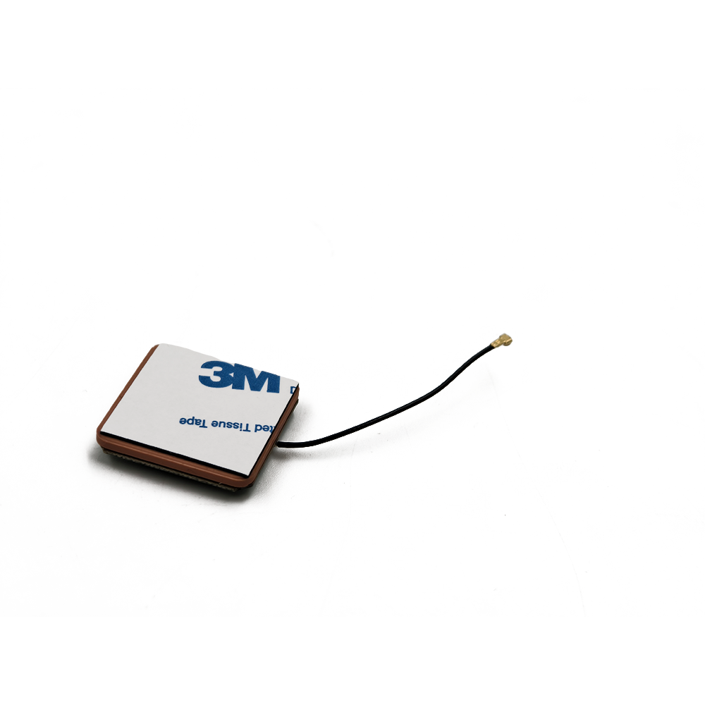

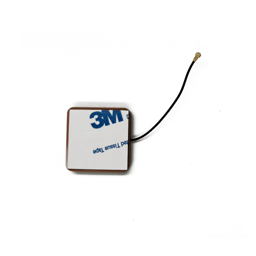

In the era of compact electronics and portable geospatial technology, small-sized RTK (Real-Time Kinematic) ceramic patch antennas have emerged as a critical innovation, enabling centimeter-level positioning in devices where space is at a premium. These antennas combine the high precision of RTK technology with the miniaturization made possible by ceramic patch designs, addressing the growing demand for compact, lightweight positioning solutions in applications such as micro-drones, wearable surveying tools, and IoT (Internet of Things) sensors. Unlike larger RTK antennas, which often prioritize gain over size, small-sized ceramic patch models achieve sub-centimeter accuracy within a footprint as small as 15x15x5 millimeters, making them ideal for integration into space-constrained systems.
Ceramic patch antennas owe their compactness to the high dielectric constant of their substrate material, which allows for a significant reduction in size compared to traditional antennas. For RTK applications, this miniaturization is paired with design optimizations to maintain low phase center variation (PCV) and multi-frequency support—two key factors for achieving centimeter-level accuracy. Typically operating across GPS L1/L2, GLONASS G1/G2, Galileo E1/E5, and BeiDou B1/B2 bands, these antennas enable the correction of ionospheric and tropospheric errors, ensuring that even in a small form factor, RTK performance remains uncompromised.
The adoption of small-sized RTK ceramic patch antennas has accelerated in industries where portability and precision are equally critical. For example, in search and rescue operations, lightweight drones equipped with these antennas can navigate tight spaces while providing precise location data, aiding in the rapid localization of survivors. In precision agriculture, small sensors mounted on farm equipment use these antennas to track soil conditions with centimeter accuracy, enabling targeted irrigation and fertilization. As the demand for miniaturized yet high-precision geospatial tools continues to grow, these antennas are becoming indispensable, proving that size does not have to be a barrier to accuracy.
Core Design Features for Miniaturization and RTK Performance
Small-sized RTK ceramic patch antennas are engineered with a focus on balancing size reduction with the precision required for RTK operation:
High-Dielectric Ceramic Substrate: The foundation of these antennas is a ceramic substrate with a high dielectric constant (εr = 20–80), which allows for significant size reduction. The wavelength of a signal in a material with a high dielectric constant is shorter than in free space, enabling the patch element to be much smaller than a comparable antenna on a low-dielectric substrate. For example, a patch antenna on a substrate with εr = 40 will have a length of approximately 15 millimeters for the GPS L1 band (1575.42 MHz), compared to 50 millimeters on a substrate with εr = 2. This miniaturization is critical for fitting into compact devices.
Low Phase Center Variation (PCV) Design: To maintain RTK accuracy in a small form factor, these antennas are designed with PCV values of less than 1–2 millimeters across all satellite angles. This is achieved through symmetric patch geometry and precise manufacturing tolerances. The patch element is often a square or circular shape with balanced feed points, ensuring that the phase center remains stable regardless of the satellite’s elevation or azimuth. Advanced simulation tools, such as electromagnetic field solvers, are used to optimize the patch layout, minimizing phase shifts caused by edge effects or material inhomogeneities.
Multi-Frequency and Multi-Constellation Support: Small-sized RTK ceramic patch antennas support multiple GNSS frequencies to enable RTK corrections. This is accomplished through either a single multi-resonant patch or a stacked patch design, where two or more patches are layered on the same substrate, each tuned to a different frequency band. For example, a stacked design may include a lower patch resonant at L2 (1227.60 MHz) and an upper patch resonant at L1 (1575.42 MHz), allowing simultaneous reception of both bands. This multi-frequency capability is essential for correcting ionospheric delays, a prerequisite for centimeter-level accuracy.
Integrated Matching Network: Due to the high dielectric constant of the ceramic substrate, the impedance of the patch antenna is typically much lower than the 50-ohm impedance of standard coaxial cables. To address this, a compact matching network—consisting of microstrip lines, inductors, or capacitors—is integrated into the antenna design. This network transforms the patch’s impedance to 50 ohms, ensuring maximum power transfer between the antenna and the receiver while minimizing signal reflections and loss.
Construction Components
The physical construction of these antennas combines precision manufacturing with durable materials to ensure performance in small packages:
Ceramic Substrate and Patch Element: The substrate is a high-purity ceramic material, such as barium titanate or alumina, with a tightly controlled dielectric constant and low loss tangent (<0.001). This ensures consistent signal propagation and minimal energy loss. The patch element is a thin layer (5–10 micrometers) of high-conductivity metal—usually copper or gold—deposited onto the ceramic substrate using sputtering or screen-printing techniques. Gold plating is often used for its excellent conductivity and corrosion resistance, critical for long-term reliability in harsh environments.
Ground Plane: A continuous ground plane, made from the same metal as the patch, covers the opposite side of the ceramic substrate. This ground plane acts as a reflector, enhancing the antenna’s radiation efficiency and providing shielding from noise generated by nearby electronics. In some designs, the ground plane extends beyond the edges of the substrate to further reduce interference and improve impedance matching. For extremely small antennas, the ground plane may be integrated into the device’s circuit board to save space.
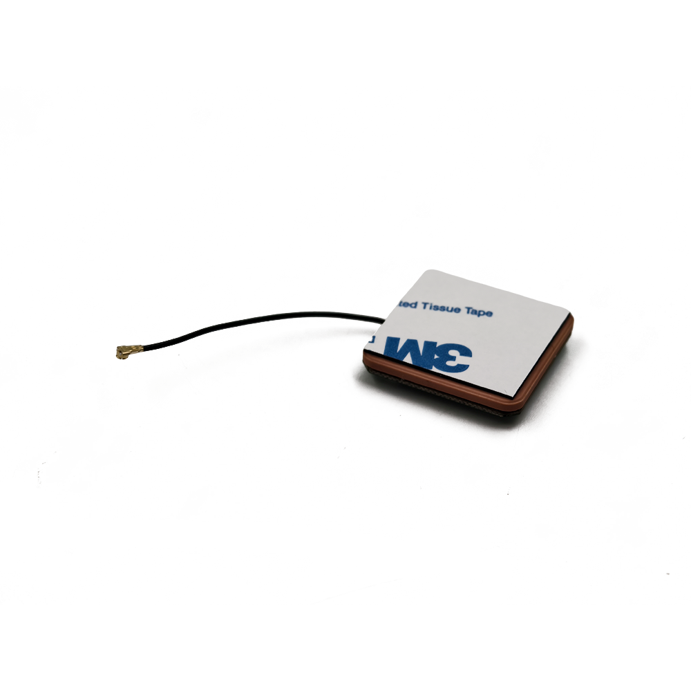
Feed Structure: The antenna is fed via a microstrip line or a coaxial probe connected to the patch element. Microstrip feeds are more common in small-sized designs due to their compactness; the feed line is etched onto the same substrate as the patch, with its width and length optimized to match the antenna’s impedance. Coaxial probes are used in applications requiring higher power handling but may increase the antenna’s profile slightly. The feed point is positioned off-center to optimize impedance matching across all supported frequencies.
Encapsulation and Protection: To protect the delicate ceramic substrate and metal layers, the antenna is often encapsulated in a thin layer of epoxy or overmolded with a low-dielectric plastic (e.g., PEEK or polyimide). This encapsulation provides mechanical strength and environmental protection (water, dust, and temperature resistance) without significantly affecting the antenna’s performance. The encapsulation layer is typically less than 1 millimeter thick to minimize signal attenuation.
Integration with Circuitry: In many cases, the antenna is mounted directly onto the device’s printed circuit board (PCB) using surface-mount technology (SMT), reducing the need for bulky connectors and cables. This integration minimizes signal loss and ensures a compact overall design. The PCB may include additional components, such as low-noise amplifiers (LNAs) or filters, positioned close to the antenna to amplify weak signals and reduce interference.
Working Principles
Small-sized RTK ceramic patch antennas operate by leveraging the properties of high-dielectric materials to capture and process GNSS signals efficiently in a compact form, enabling RTK’s high-precision positioning:
Signal Reception and Resonance: The ceramic patch element resonates at the frequencies of the target GNSS bands (e.g., L1 and L2). When a satellite signal impinges on the patch, it induces an electric current, which is guided through the feed structure to the receiver. The high-dielectric ceramic substrate concentrates the electromagnetic field near the patch, allowing for efficient signal capture despite the antenna’s small size. The symmetric design ensures that the phase center remains stable, so the distance measured between the antenna and each satellite is consistent across all angles.
Multi-Frequency Processing: For RTK operation, the antenna must receive signals from at least two frequency bands per GNSS constellation. In a stacked patch design, each layer resonates at a different frequency, capturing both L1 and L2 signals simultaneously. These signals are passed through the matching network to the receiver, which uses the frequency difference to calculate and correct for ionospheric delays. This correction is critical for achieving centimeter-level accuracy, as ionospheric effects can introduce errors of several meters if uncompensated.
RTK Correction Application: The receiver processes the multi-frequency signals, using carrier-phase measurements to determine the antenna’s position. The low PCV of the antenna ensures that these phase measurements are consistent, allowing the receiver to resolve integer ambiguities—the number of full carrier-wave cycles between the satellite and antenna—with high confidence. The receiver then applies RTK corrections from a base station, adjusting for residual errors such as tropospheric delays and satellite clock offsets, resulting in a final position accuracy of 1–2 centimeters.
Interference Mitigation: The ground plane and compact design help reduce interference from nearby electronics and multipath reflections. The ground plane blocks signals coming from below the antenna, minimizing interference from the device itself (e.g., a drone’s motors or a sensor’s circuitry). The small size of the antenna also reduces the likelihood of multipath reflections from nearby objects, as the antenna’s radiation pattern is more focused toward the sky.
Integration with Receiver Electronics: The close proximity of the antenna to the receiver’s LNA (often mounted on the same PCB) minimizes signal loss, ensuring that weak satellite signals are amplified before noise can degrade them. This is particularly important for small antennas, which may have lower gain than larger models; the LNA compensates for this by boosting signal strength with minimal added noise (noise figure <1 dB), preserving the high signal-to-noise ratio needed for RTK processing.
Advantages of Small-Sized RTK Ceramic Patch Antennas
These antennas offer unique benefits that make them ideal for compact, high-precision applications:
Ultra-Compact Form Factor: Their small size (often <20x20x5 mm) allows integration into devices where larger antennas would be impractical, such as micro-drones, wearable trackers, and small IoT sensors. For example, a micro-drone used for indoor mapping can carry a small ceramic patch antenna without sacrificing maneuverability, enabling precise navigation in tight spaces.
Lightweight Design: Weighing as little as 1–5 grams, these antennas minimize payload weight, extending battery life in portable devices. This is critical for applications like battery-powered agricultural sensors, which need to operate for months between charges, or small drones, where every gram affects flight time.
Low Profile and Easy Integration: Their flat, surface-mountable design allows for seamless integration into circuit boards, reducing the need for external mounts or connectors. This simplifies manufacturing and reduces the overall size of the device, making them suitable for consumer electronics and industrial sensors alike.
Cost-Effective Production: Ceramic patch antennas can be mass-produced using automated manufacturing techniques (e.g., screen printing, sputtering), reducing per-unit costs compared to larger, more complex antennas. This cost efficiency makes them accessible for high-volume applications, such as fleet tracking or consumer drones.
Stable Performance in Dynamic Environments: The rigid ceramic substrate and symmetric design ensure stable phase center variation and radiation patterns, even when the antenna is subjected to vibration or minor orientation changes. This makes them reliable for applications like drone racing or handheld surveying tools, where movement is constant.
Challenges and Limitations
Despite their advantages, small-sized RTK ceramic patch antennas face several challenges:
Lower Gain Compared to Larger Antennas: The small size and high-dielectric substrate result in lower gain (typically 2–5 dBi) compared to larger RTK antennas (8–12 dBi). This can reduce sensitivity to weak signals, such as those from low-elevation satellites or in urban canyons, potentially limiting performance in challenging environments.
Narrower Bandwidth: High-dielectric ceramic substrates tend to have narrower bandwidths, making it harder to support multiple frequency bands without performance degradation. While stacked patch designs address this, they increase complexity and may slightly increase the antenna’s size or profile.
Susceptibility to Environmental Factors: The small form factor leaves less room for robust environmental protection, making these antennas more vulnerable to extreme temperatures, moisture, or physical damage. While encapsulation helps, it may not provide the same level of protection as the rugged enclosures of larger antennas, limiting their use in harsh industrial environments.
Sensitivity to Placement and Interference: Their compact size makes them more sensitive to placement on the device; proximity to metal components or other electronics can distort the radiation pattern or introduce interference. This requires careful PCB design to ensure optimal performance, adding complexity to device development.
Phase Center Sensitivity to Manufacturing Tolerances: Achieving low PCV in a small antenna requires extremely tight manufacturing tolerances (±0.01 mm for patch dimensions). Even minor variations in ceramic substrate thickness or patch geometry can increase phase center variation, reducing RTK accuracy. This increases production costs and requires rigorous quality control.
Applications
Small-sized RTK ceramic patch antennas are deployed in a wide range of compact, precision-critical applications:
Micro-Drones and UAVs: Small drones used for indoor mapping, inspection of tight spaces (e.g., pipelines, tunnels), or consumer racing rely on these antennas to maintain centimeter-level positioning without adding significant weight or size. For example, a micro-drone inspecting a bridge’s internal structure can use the antenna to navigate with precision, avoiding collisions while capturing detailed imagery.
Wearable Surveying Tools: Surveyors and construction workers use wearable devices (e.g., smart glasses, handheld tablets) equipped with these antennas to collect precise location data in real time. The small size ensures the devices remain lightweight and unobtrusive, while RTK accuracy enables on-the-spot measurements for tasks like stakeout or as-built verification.
Precision Agriculture Sensors: Small, battery-powered sensors placed in fields use these antennas to track soil moisture, nutrient levels, and crop growth with centimeter accuracy. The sensors transmit data to a central system, enabling farmers to apply inputs precisely where needed, reducing waste and improving yields. The low power consumption of the antennas ensures the sensors can operate for extended periods.
IoT and Asset Tracking: High-value assets, such as shipping containers, medical equipment, or industrial tools, are tracked using small IoT devices with RTK ceramic patch antennas. This allows for precise localization (e.g., within a warehouse or construction site) and real-time monitoring, improving inventory management and security.
Robotics and Autonomous Systems: Small robots used in manufacturing, logistics, or search and rescue use these antennas to navigate with precision in dynamic environments. For example, a warehouse robot can use RTK positioning to move goods with centimeter accuracy, optimizing storage space and reducing collisions.
Future Trends
The development of small-sized RTK ceramic patch antennas is driven by advances in materials science, manufacturing, and GNSS technology:
Higher Dielectric Constant Ceramics: Research into new ceramic materials with dielectric constants exceeding 100 will enable further miniaturization, allowing antennas to be shrunk to 10x10x3 mm or smaller while maintaining performance. These materials will also have lower loss tangents, reducing signal attenuation and improving gain.
3D Printing of Ceramic Structures: Additive manufacturing techniques for ceramics will enable complex, customized antenna designs that optimize performance in specific form factors. 3D printing allows for precise control over substrate geometry and dielectric properties, enabling multi-frequency operation in even smaller packages.
Integration with AI-Powered Receivers: Future antennas will work with AI-driven receivers that adaptively correct for environmental interference and manufacturing variations. Machine learning algorithms will analyze signal patterns to compensate for the antenna’s small size, improving performance in weak-signal environments.
Multi-Sensor Fusion: Small-sized RTK ceramic patch antennas will increasingly be integrated with other sensors, such as IMUs (Inertial Measurement Units) or LiDAR, in compact modules. This fusion will compensate for temporary GNSS signal loss (e.g., in tunnels) by using data from other sensors, ensuring continuous high-precision positioning.
Enhanced Environmental Hardening: Advances in encapsulation materials, such as nanocomposite epoxies, will improve the antennas’ resistance to extreme temperatures (-50°C to +125°C), moisture, and vibration. This will expand their use in harsh environments, such as oil and gas exploration or space applications.
Conclusion
Small-sized RTK ceramic patch antennas represent a remarkable convergence of miniaturization and precision, proving that high-accuracy geospatial positioning is possible even in the smallest devices. By leveraging high-dielectric ceramics and optimized design, these antennas deliver centimeter-level RTK performance in packages as small as 15x15x5 millimeters, enabling their integration into micro-drones, wearable tools, and IoT sensors. Their compactness, lightweight design, and cost-effectiveness make them indispensable for applications where size and weight are critical, without compromising on accuracy.
While challenges such as lower gain, narrow bandwidth, and sensitivity to manufacturing tolerances exist, ongoing advancements in materials and manufacturing are addressing these limitations. Future antennas will be even smaller, more robust, and better integrated with other sensors, expanding their role in emerging technologies like autonomous robotics and precision IoT.
As the demand for compact, high-precision geospatial tools continues to grow, small-sized RTK ceramic patch antennas will play a central role in enabling innovation across industries. From enabling micro-drones to navigate tight spaces with precision to powering wearable surveying devices that simplify fieldwork, these antennas are reshaping what is possible in geospatial technology—proving that great things truly can come in small packages.

 86 0755 2819 9597
Lucy Yang | lucy.y@toxutech.com
Nicole Li | nicole@toxutech.com
Dotty Zhao | sales04@toxutech.com
Global Business Director / Sales Team / Global Operations


 En
En Cn
Cn Korean
 Home >


