

-
Products -PCBA Manufacturing RF Connectors RF Cable Assemblys Embedded Antennas External Antennas Positioning Chips and Modules
RF Connectors

RF Cable Assemblys
Embedded Antennas
External Antennas
Positioning Chips and Modules


 Language


Language


In the vast ecosystem of Global Navigation Satellite System (GNSS) technology, where applications range from consumer smartphones to mission-critical military operations, the screw-mount waterproof GPS antenna occupies a specific and vital niche. It represents the workhorse solution for demanding outdoor and mobile environments where reliability, durability, and consistent performance are non-negotiable. Unlike its smaller, integrated SMD cousins, this antenna type is an external, active component designed to be mounted on an external surface—a vehicle roof, a boat mast, a surveyor's pole, or an industrial cabinet—to secure an unobstructed view of the sky, which is paramount for superior satellite reception.
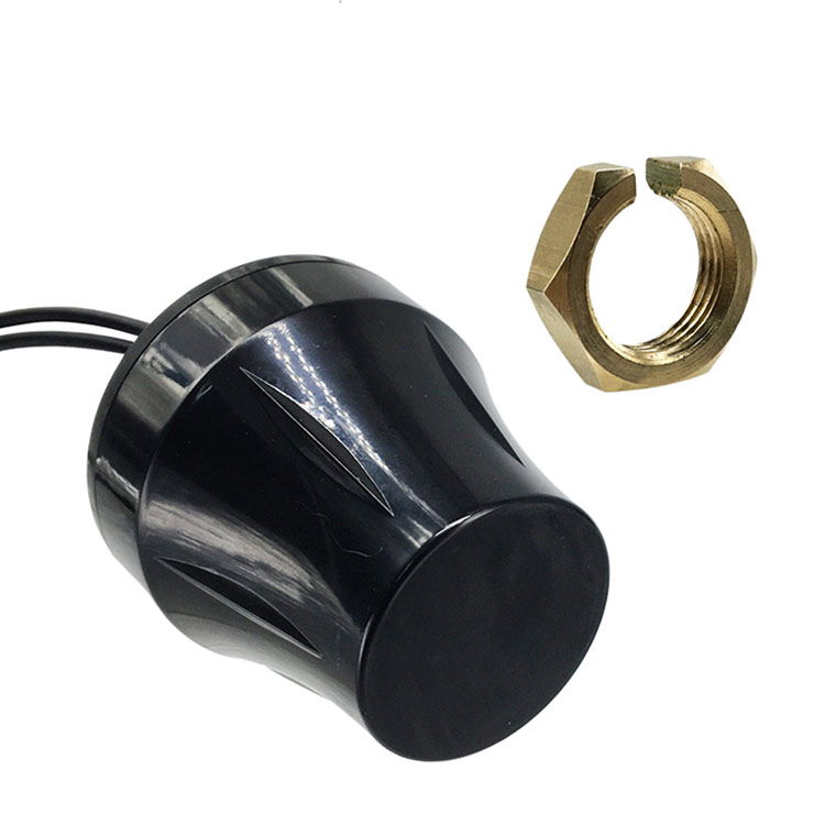
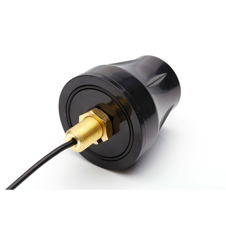
The defining characteristic of this antenna category is its combination of a robust mechanical mounting system and environmental sealing. The "screw-mount" typically refers to a threaded base, often following a standard pattern like a ¼"-20 UNC thread (common in camera tripods) or an M5/M6 metric thread. This allows for a strong, vibration-resistant, and permanent attachment to a metal surface or a dedicated mounting bracket. The "waterproof" qualification, often quantified by an Ingress Protection (IP) rating such as IP67 or IPx7 (submersible in 1m of water for 30 minutes) or IP69K (resistant to high-pressure, high-temperature water jets), signifies its ability to withstand the harshest environmental conditions. This includes not just rain and splashing water, but also humidity, salt spray, ice, dust, and extreme temperatures.
These antennas are almost exclusively active antennas, meaning they incorporate a Low-Noise Amplifier (LNA) within their housing. This is a critical differentiator from passive antennas. The primary function of this integrated LNA is to amplify the incredibly weak signals received from GPS and other GNSS satellites (e.g., GLONASS, Galileo, BeiDou) before they are transmitted through a coaxial cable to the receiver unit. This amplification at the source compensates for the signal loss that inevitably occurs over the length of the cable, which can be several meters long in applications like trucks or boats. By ensuring a strong signal arrives at the receiver, the active antenna system dramatically improves signal-to-noise ratio (SNR), acquisition time, and overall positional accuracy.
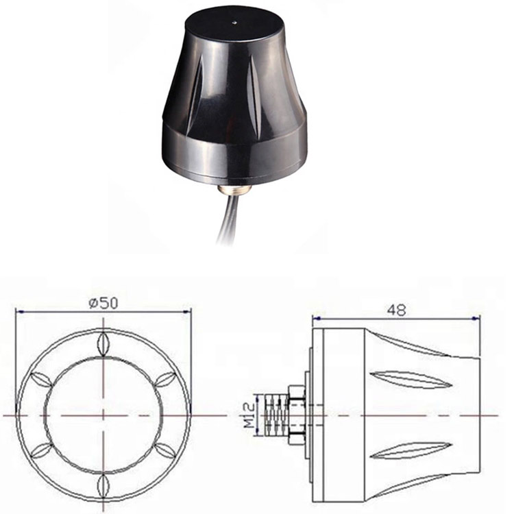
The typical physical form factor is a low-profile, hemispherical or dome-shaped radome. This aerodynamic shape is designed to minimize wind load, prevent the accumulation of debris, and present a low physical profile on a vehicle's roof. The radome material is a critical component, typically made from high-grade engineering plastics such as polycarbonate or ASA (Acrylonitrile Styrene Acrylate). These materials are chosen for their exceptional durability, resistance to UV radiation (to prevent yellowing and brittleness from sun exposure), and, crucially, their radio frequency (RF) transparency. They must allow the L1 (1575.42 MHz) and L2 (1227.60 MHz) frequency signals to pass through with minimal attenuation or distortion.
The market for screw-mount waterproof GPS antennas is diverse and serves industries where failure is not an option. Key sectors include:
Marine Navigation: On recreational boats, fishing vessels, and commercial shipping, where reliable positioning is critical for safety and navigation in corrosive saltwater environments.
Automotive and Telematics: For fleet management, tracking of trucks, buses, and emergency vehicles, providing constant location data regardless of weather.
Agriculture: On tractors and harvesters for precision farming guidance systems, which operate in dusty, humid, and vibration-intensive conditions.
Surveying and Geomatics: Providing high-precision positioning for mapping and construction, often requiring support for multi-band (L1/L2/L5) and multi-constellation signals for centimeter-level accuracy.
Aviation: Used on general aviation aircraft and Unmanned Aerial Vehicles (UAVs) for navigation and guidance.
Industrial IoT and Critical Infrastructure: Timing synchronization for cellular base stations, power grids, and financial networks, often installed on remote towers exposed to the elements.
In essence, the screw-mount waterproof GPS antenna is not a consumer-grade gadget but a high-performance, industrial-grade tool. It is engineered for one primary purpose: to provide a rock-solid, unwavering link to the satellite constellation, forming the most reliable foundation upon which a positioning, navigation, or timing (PNT) solution can be built. Its overview is one of resilience, precision, and purpose-built design for the challenges of the real world.
The design and construction of a screw-mount waterproof GPS antenna is a meticulous exercise in balancing electromagnetic performance, mechanical robustness, and environmental sealing. It is a multi-layered system where every material and component is chosen for a specific purpose, often involving trade-offs between cost, size, and performance.
1. The Radiating Element: The Heart of the Antenna
At the core of the antenna lies the radiating element. For most high-performance screw-mount antennas, this is a quadrifilar helix (QFH) or a patch antenna.
Quadrifilar Helix (QHF): This design consists of four helical elements etched or wound onto a cylindrical former. It is renowned for its excellent hemispherical coverage and right-hand circular polarization (RHCP), which perfectly matches the polarization of GPS signals. Its radiation pattern provides good gain at low elevation angles, making it ideal for tracking satellites near the horizon, a common scenario in urban canyons or mountainous terrain. The QFH is often favored for its robust performance across a wide angular range.
Ceramic Patch Antenna: A flat, square conductive patch printed on a ceramic substrate with a high dielectric constant. This design is more common in low-profile, smaller radomes. Modern patch designs can be engineered to offer very wide bandwidth, supporting multiple GNSS bands (L1, L2, L5) simultaneously. Their radiation pattern is typically more directional (broadside), but can be shaped with the ground plane and radome to provide a wide beamwidth.
The choice between QFH and patch involves trade-offs: QFH often offers better low-elevation performance, while a advanced patch can be more compact and better for multi-band applications.
2. The Ground Plane
Beneath the radiating element lies the ground plane, a critical component that significantly influences the antenna's performance characteristics, including its gain, radiation pattern, and bandwidth. In a screw-mount antenna, the ground plane is typically a solid metal disc, often made of aluminum or a zinc alloy. The vehicle's metal roof onto which it is mounted often acts as an extension of this ground plane, further enhancing performance. The size and shape of this ground plane are carefully engineered to optimize the antenna's efficiency and to create a null in the radiation pattern directly beneath the antenna, rejecting multipath signals that reflect off the ground.
3. The Low-Noise Amplifier (LNA)
Mounted directly adjacent to or beneath the radiating element is the active component: the LNA. This is typically a semiconductor amplifier chip (MMIC) based on Gallium Arsenide (GaAs) or advanced Silicon Germanium (SiGe) technology, chosen for their low noise characteristics at GHz frequencies. The LNA is housed on a small printed circuit board (PCB) and is designed to provide high gain (typically 26-40 dB) with an exceptionally low noise figure (often < 2 dB, with high-end models < 1 dB). This board also includes necessary passive components for biasing, filtering, and impedance matching. A critical design feature is the inclusion of a bandpass filter either before or within the LNA stage. This filter is essential for rejecting powerful out-of-band interference from cellular, WiFi, and VHF/UHF radio transmitters, which could otherwise overload the sensitive GNSS receiver.
4. The Housing and Radome
The entire electronic assembly is encased within a protective housing. This consists of two main parts:
Base: The lower part is usually metal (e.g., die-cast zinc or aluminum), providing both the threaded screw-mount and an excellent RF shield. It acts as the physical ground plane and provides electromagnetic isolation for the internal electronics from external noise. The coaxial connector (typically TNC, SMA, or N-type) is integrated into this base, with a waterproof seal around it.
Radome: The upper dome is made of RF-transparent plastic. The material selection is crucial. Polycarbonate offers high impact resistance, while materials like ASA or polyetherimide (PEI) offer better UV stability and higher heat deflection temperatures. The thickness and material properties are engineered to have minimal effect on the RF signal, ensuring the antenna's performance is not detuned.
5. Environmental Sealing
Achieving a waterproof rating like IP67 or IPx7 is a feat of mechanical design. It involves:
Gaskets and O-Rings: A primary silicone rubber gasket is compressed between the radome and the base housing when they are ultrasonically welded or screwed together. Silicone is chosen for its wide temperature tolerance, longevity, and excellent compression set properties.
Potting: To protect the internal LNA PCB from humidity, condensation, and shock/vibration, it is often potted or encapsulated in a thermosetting resin or silicone gel. This compound physically locks all components in place, provides a moisture barrier, and aids in heat dissipation from the LNA.
Sealed Connector: The coaxial connector interface uses a rubber seal and a threaded coupling (e.g., TNC) to ensure a waterproof connection to the cable.
6. The Cable Assembly
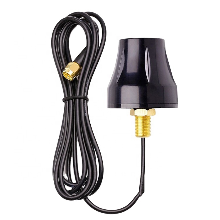
The antenna is typically supplied with an integrated coaxial cable. This is not a standard cable but a low-loss type, such as RG-174 or similar, with a specified shield coverage to prevent noise ingress. The length is a critical part of the system design, as longer cables introduce more signal loss, which the LNA's gain is specifically calibrated to overcome. The cable is permanently attached to the antenna base with a strain relief to prevent the connector from being pulled off.
In summary, the construction of a screw-mount waterproof GPS antenna is a complex assembly of precision RF components, robust mechanical parts, and meticulous sealing techniques, all working in concert to create a single, highly reliable unit capable of performing in the world's most challenging environments.
The working principle of a screw-mount waterproof GPS antenna can be dissected into three fundamental stages: signal reception, signal amplification and filtering, and signal transmission. Its operation is a continuous process of capturing incredibly faint whispers from space, conditioning them, and delivering a robust signal to the receiver, all while being exposed to the elements.
1. Signal Reception and the Physics of Capture
The primary function of the antenna's radiating element (QFH or patch) is to convert electromagnetic waves from GPS satellites into electrical currents. GPS signals are right-hand circularly polarized (RHCP). This polarization is used to mitigate errors caused by signal reflection (multipath); a reflected signal typically becomes left-hand circularly polarized (LHCP) or elliptically polarized and is therefore partially rejected by the RHCP antenna. The QFH or patch element is specifically designed to be most sensitive to RHCP waves.
The signal strength from a GPS satellite is astonishingly weak by the time it travels over 20,000 kilometers to the Earth's surface, typically around -130 dBm. This is significantly below the thermal noise floor present in any electronic system. The antenna's efficiency at capturing this weak energy is paramount. Its radiation pattern is designed to be hemispherical, providing near-uniform gain for satellites anywhere above the horizon. This ensures that the antenna can maintain a lock on multiple satellites simultaneously, which is essential for calculating an accurate position fix.
2. The Critical Role of the Low-Noise Amplifier (LNA)
The minute electrical current induced in the radiating element by the satellite signal is virtually useless for transmission over a cable. This is where the integrated LNA performs its most critical task. The signal is fed directly from the radiating element to the input of the LNA with the shortest possible transmission path to minimize any initial loss.
The LNA's purpose is twofold:
Amplification: It provides a high degree of gain, typically between 26 and 40 decibels (dB). This means it boosts the power of the signal (and the inherent noise present at its input) by a factor of 400 to 10,000 times.
Minimal Noise Addition: Crucially, it accomplishes this amplification while adding as little internal electronic noise as possible. Its performance is measured by its Noise Figure (NF), which for a high-quality antenna is typically below 2 dB. A lower NF means the amplified signal has a better Signal-to-Noise Ratio (SNR).
This pre-amplification at the antenna itself is the key advantage of an active antenna. It ensures that the signal is boosted to a robust level before it enters the lossy coaxial cable.
3. Filtering for Signal Purity
The environment is saturated with RF noise from various sources: cellular towers, FM radio, TV broadcasts, WiFi routers, and mobile radios. These signals are often millions of times stronger than the desired GPS signal. If allowed to enter the LNA, they could desensitize it or cause intermodulation distortion, effectively blocking the GPS signals.
To prevent this, a bandpass filter is integrated into the RF path, usually between the radiator and the LNA or as part of the LNA's input circuit. This filter is designed to have a very low insertion loss within the GNSS frequency bands (e.g., 1550-1610 MHz to cover GPS L1, GLONASS L1, Galileo E1, and BeiDou B1) but very high rejection outside this band. This allows the weak GNSS signals to pass through unimpeded while attenuating powerful out-of-band interferers.
4. Transmission and System Integration
The amplified and filtered signal is then fed through the integrated coaxial cable to the GNSS receiver. The receiver provides DC power to the antenna's LNA through the same coaxial cable via a system called DC bias injection or "phantom power." This is achieved using a bias tee circuit: inside the receiver, a DC voltage is applied to the center conductor of the cable, and inside the antenna, a DC-blocking capacitor separates this DC power from the RF signal, channeling it to power the LNA. This elegant solution eliminates the need for a separate power wire.
The length and quality of the coaxial cable are non-trivial factors. The cable has a certain amount of signal loss (attenuation) per meter, which increases with frequency. The gain of the LNA is specifically chosen to ensure that after the signal has traveled the length of the cable and suffered this attenuation, it arrives at the receiver at an optimal power level—strong enough for the receiver to process effectively but not so strong that it causes overload (saturation).
In essence, the screw-mount antenna works as a sensitive, external, pre-processing stage for the GNSS receiver. It ensures that the receiver is presented with a clean, strong signal, maximizing the number of satellites it can track and the accuracy and reliability of the positioning solution, regardless of the weather or the length of the cable run.
The screw-mount waterproof GPS antenna offers a set of compelling advantages that make it the preferred choice for many professional and demanding applications. However, these advantages come with inherent challenges and trade-offs that must be carefully considered during system design and integration.
Advantages:
Superior Performance and Reliability: This is the paramount advantage. By being mounted externally, typically on a metal surface, the antenna is guaranteed an unobstructed view of the sky. This maximizes the number of satellites it can "see" and track at any given time, which directly translates to faster time-to-first-fix (TTFF), higher positional accuracy, and better reliability. The integrated ground plane and the vehicle's roof itself help to create a optimal radiation pattern with high gain towards the horizon and a null below to reject ground-reflected multipath signals.
Exceptional Durability and Environmental Resistance: Built to IP67, IPx7, or even MIL-STD-810 standards, these antennas are engineered to survive where others would fail. They are completely immune to rain, snow, ice, dust, and humidity. Their UV-resistant radomes do not degrade in direct sunlight, and their robust construction can withstand constant vibration, shock, and extreme temperature cycles. This makes them ideal for permanent, "set-and-forget" installations in harsh environments.
Optimized Signal-to-Noise Ratio (SNR): The integration of a high-gain, low-noise amplifier directly at the antenna feed point is a massive benefit. It overcomes the signal loss of the coaxial cable, ensuring a strong signal reaches the receiver. This is in stark contrast to a passive antenna, where the signal would be attenuated by the cable loss before any amplification, severely degrading the system's overall noise figure and sensitivity.
Reduced System Noise and Interference: The metal housing acts as a Faraday cage, providing excellent electromagnetic shielding for the sensitive LNA inside. This protects it from external noise generated by the vehicle's engine, alternator, electronic control units (ECUs), and other onboard radios. Furthermore, being located outside the vehicle avoids the signal attenuation caused by modern laminated windshields, which often contain metallic layers that can block GNSS signals.
Ease of Installation and Flexibility: The standardized screw-mount and integrated cable make installation straightforward. It can be easily positioned on a roof or a mast for optimal sky view. The availability of antennas with different cable lengths and connector types provides flexibility for various vehicle sizes and system layouts.
Challenges and Limitations:
Cost: High-quality screw-mount antennas are significantly more expensive than passive or SMD antennas. The cost is driven by the robust materials (die-cast metal, high-grade plastics), the precision RF components (low-noise amplifier, filter), the complex sealing and potting processes, and the rigorous testing required to meet environmental specifications.
Size, Profile, and Aesthetics: These antennas are larger and more conspicuous than embedded solutions. Their external mounting means they are always visible, which can be considered aesthetically unpleasing on some vehicles and requires drilling a hole in the roof for the cable, which may void warranties and can lead to water ingress if not sealed properly.
Installation Complexity and Cable Routing: While the mount itself is simple, the overall installation is more involved than plugging in a USB device. It requires routing a coaxial cable from the exterior to the interior of the vehicle, which often involves removing interior trim panels and finding a safe path through the vehicle's firewall or grommets. This can be a time-consuming and technically challenging process for non-professionals.
Power Dependency: As active antennas, they require a DC power source from the receiver (via the coaxial cable). If this power is interrupted, or if the receiver does not support bias-tee functionality, the antenna becomes completely non-functional. A passive antenna would still work, albeit with degraded performance.
Potential for Damage: Being mounted on the exterior makes them susceptible to physical damage from low-hanging branches, automatic car washes, vandalism, or accidental impacts. While they are designed to be robust, they are not indestructible.
Maintenance: Although designed to be maintenance-free, the cable and connector can suffer wear and tear over time. The seal around the cable entry point and the mounting hole must be periodically inspected to ensure it remains watertight.
In conclusion, the advantages of the screw-mount antenna—unmatched performance, durability, and noise immunity—make it the gold standard for professional, automotive, and marine applications where reliability is critical. The challenges—primarily cost, size, and installation complexity—are the necessary trade-offs for achieving this level of performance and resilience. The choice to use one is a decision to prioritize ultimate reception quality and reliability above all other factors.
The screw-mount waterproof GPS antenna is not a general-purpose component; it is a precision tool deployed in applications where its specific advantages—external mounting, ruggedness, and high performance—are absolutely essential. Its use cases are diverse, spanning land, sea, and air, and its future evolution is closely tied to advancements in satellite navigation technology itself.
Applications:
Marine Navigation: This is a classic and critical application. On everything from small sailboats to massive container ships, reliable GNSS is a matter of safety. The antenna is typically mounted on the radar arch or atop the pilot house, providing a clear 360-degree view of the sky. Its waterproof (and specifically saltwater-proof) construction is vital in the corrosive marine environment. It feeds chart plotters, autopilots, and AIS transponders, forming the backbone of the vessel's navigation suite.
Automotive Telematics and Fleet Management: The backbone of the logistics industry. Thousands of trucks, delivery vans, and buses are equipped with these antennas to provide real-time location data for route optimization, fuel monitoring, driver behavior analysis, and theft recovery. The screw-mount provides a secure, permanent attachment that can withstand millions of miles of vibration and exposure to all weather conditions. They are also used in emergency vehicles (police, fire, ambulance) where reliable location data is critical for dispatch and response.
Precision Agriculture: Modern farming relies on centimeter-level accuracy for guided tractor systems, variable rate application (of seed, fertilizer, pesticide), and yield mapping. This high-precision GNSS (often using RTK or PPP corrections) requires a high-performance antenna capable of receiving multiple frequencies (L1/L2/L5). The antenna is mounted on the roof of the tractor or sprayer, enduring dust, chemicals, heat, and intense vibration.
Surveying, Mapping, and Construction: Surveyors use these antennas mounted on poles or fixed base stations to provide the reference data for creating highly accurate maps and guiding construction equipment. The demand here is for the highest possible accuracy, driving the need for multi-band, multi-constellation antennas that can mitigate atmospheric errors and provide rapid, reliable fixes.
Aviation: While commercial aviation uses more specialized antennas, the general aviation and Unmanned Aerial Vehicle (UAV/drone) markets are significant users. On drones, a small, lightweight screw-mount antenna provides the precise positioning required for autonomous flight, mapping, and photography. For general aviation aircraft, they serve as a primary or backup source of position data for navigation displays.
Timing and Synchronization: This is a less visible but utterly critical application. Cellular base stations (4G/5G), electrical power grids, and financial trading networks all rely on precise time synchronization, often derived from GPS. These antennas are mounted on towers or rooftops, providing a continuous, stable time reference that is immune to jitter and drift, ensuring the smooth operation of critical infrastructure.
Future Trends:
Multi-Band and Multi-Constellation Support: The future is multi-frequency. The next generation of high-precision applications requires antennas that can simultaneously receive L1, L2, and L5 signals from all available constellations (GPS, GLONASS, Galileo, BeiDou, QZSS). This allows for advanced error correction and faster convergence to centimeter-level accuracy. Future antennas will feature radiating elements (like wideband patches) and filters designed to cover this entire spectrum efficiently.
Integrated Anti-Jamming and Anti-Spoofing (AJA): The threat of intentional GPS jamming and spoofing is growing. Future high-end screw-mount antennas will increasingly incorporate built-in protection. This can take the form of controlled reception pattern antennas (CRPA) that use multiple elements to form nulls in the direction of jammers, or integrated filters and algorithms to detect and mitigate spoofed signals. This will be essential for military, critical infrastructure, and autonomous vehicle applications.
Miniaturization and Aesthetic Integration: While performance will remain key, there is a trend towards lower-profile, more aesthetically pleasing designs that blend better with vehicle rooflines. Advances in materials and RF design will allow for smaller radomes without compromising performance.
Enhanced Connectivity and "Smart" Antennas: We may see the emergence of "smart antennas" that integrate more functionality beyond the LNA. This could include built-in correction receivers (e.g., for SBAS or L-band correction services), diagnostic capabilities (e.g., reporting signal strength, health status, and even detected jamming), and standardized digital outputs (like Ethernet) in addition to RF outputs.
Improved Materials and Sustainability: Research into new radome materials that offer even better RF transparency, impact resistance, and UV stability will continue. There may also be a growing focus on the sustainability of materials used in construction and the recyclability of the product at end-of-life.
The screw-mount waterproof GPS antenna will remain a vital component in the PNT ecosystem. Its future is not one of replacement but of enhancement—becoming more capable, more intelligent, and more resilient to meet the ever-increasing demands for accuracy, reliability, and security in a world that runs on precise location and timing.
Conclusion
The screw-mount waterproof GPS antenna stands as a testament to the principle that optimal performance often requires a purpose-built, dedicated solution. In a world increasingly moving towards miniaturization and invisible integration, this antenna type defiantly asserts the enduring value of external, ruggedized design where it matters most. It is the unsung hero of the GNSS world, providing the critical, reliable link to the satellite constellations for applications where failure is not an option—where a lost signal could mean a stranded vessel, a misdirected fleet, a ruined harvest, or a failed critical infrastructure node.
Its overview reveals a device engineered not for convenience but for excellence. Its design and construction are a masterclass in balancing electromagnetic precision with mechanical fortitude, combining a high-performance radiating element and LNA with a shell capable of withstanding the planet's harshest conditions. Its working principle is elegantly simple yet profoundly effective: capture the faintest of signals, amplify them at the source, and deliver a clean, strong signal to the receiver, all while being powered through the very cable that carries the data.
The advantages it offers are compelling and specific: unparalleled reception quality thanks to an unobstructed sky view, exceptional durability against environmental assault, and superior noise immunity. These come, however, with inherent challenges—higher cost, more complex installation, and a permanent physical presence on the exterior of a vehicle or structure. These are not drawbacks but rather the necessary trade-offs for achieving a level of performance that embedded antennas simply cannot match.
Its applications are as diverse as they are critical, forming the foundation for modern marine navigation, global logistics, precision agriculture, and the timing of our digital world. Looking forward, its evolution is clear. It will not be made obsolete but will instead advance to embrace multi-band and multi-constellation signals, incorporate sophisticated anti-jamming technologies, and perhaps even evolve into a more intelligent, connected device.
In conclusion, the screw-mount waterproof GPS antenna is far more than a simple component. It is a high-performance insurance policy against signal loss. It is the embodiment of reliability in an unpredictable world. For system designers and engineers working in demanding fields, the choice to use one is a definitive statement that performance, accuracy, and resilience are the highest priorities. It remains, and will continue to be, the gold-standard form factor for ensuring that a vital line of communication to the heavens above remains open, regardless of what happens here on Earth.

 86 0755 2819 9597
Lucy Yang | lucy.y@toxutech.com
Nicole Li | nicole@toxutech.com
Dotty Zhao | sales04@toxutech.com
Global Business Director / Sales Team / Global Operations


 En
En Cn
Cn Korean
 Home >


