

-
Products -PCBA Manufacturing RF Connectors RF Cable Assemblys Embedded Antennas External Antennas Positioning Chips and Modules
RF Connectors

RF Cable Assemblys
Embedded Antennas
External Antennas
Positioning Chips and Modules


 Language


Language


In the realm of precision geospatial measurement, Rugged RTK (Real-Time Kinematic) Surveying Antennas stand as a cornerstone technology, engineered to deliver centimeter-level positioning accuracy even in the harshest operating environments. Unlike standard GNSS antennas, which may falter under extreme weather, physical impact, or electromagnetic interference, rugged RTK antennas are purpose-built to withstand the rigors of fieldwork in sectors such as construction, mining, oil and gas, and environmental monitoring.
The core value of Rugged RTK Surveying Antennas lies in their ability to maintain consistent, high-precision signal reception in challenging conditions. RTK technology itself relies on a base station and a rover antenna: the base station remains stationary at a known position, continuously measuring GNSS signals and transmitting correction data to the rover antenna. The rover, equipped with a rugged RTK antenna, uses these corrections in real time to calculate its exact position with sub-centimeter to centimeter accuracy. This real-time correction capability is critical for applications where on-the-spot precision is non-negotiable—for example, in highway construction, where misalignments of even a few centimeters can lead to costly rework, or in mining operations, where accurate positioning of heavy machinery is essential for worker safety and operational efficiency.
The demand for Rugged RTK Surveying Antennas has surged in recent years, driven by the expansion of infrastructure projects in remote or harsh regions. For instance, the development of renewable energy projects, such as wind farms in coastal areas or solar parks in arid deserts, requires antennas that can endure salt spray, extreme temperatures, and high winds. Similarly, in disaster response scenarios—such as mapping earthquake zones or assessing flood damage—rugged RTK antennas enable rapid, accurate data collection even amid debris, heavy rain, or unstable terrain.
Historically, RTK antennas were often large, heavy, and vulnerable to environmental damage. Early models struggled with signal dropout in heavy rain or snow, and their enclosures could crack under physical impact from falling debris or rough handling. However, advancements in materials science, signal processing, and structural design have transformed these antennas into robust tools. Modern Rugged RTK Surveying Antennas integrate multi-constellation compatibility (supporting GPS, GLONASS, Galileo, and BeiDou), advanced interference mitigation, and durable enclosures that meet industry standards for ingress protection (IP) and shock resistance.
Another key aspect of their overview is their role in enabling efficient, data-driven workflows. In construction, for example, a rugged RTK antenna mounted on a bulldozer or excavator allows operators to follow design plans with precision, reducing material waste and shortening project timelines. In environmental monitoring, these antennas facilitate accurate tracking of land subsidence, glacier movement, or coastal erosion over time, providing scientists with reliable data to model climate change impacts. As industries increasingly rely on real-time, high-precision positioning to optimize operations, the importance of Rugged RTK Surveying Antennas continues to grow, making them an indispensable tool for modern field surveying.
2.1 Structural Design for Ruggedness
The structural design of Rugged RTK Surveying Antennas is centered on three core principles: durability, signal integrity, and ease of deployment in harsh conditions. Every component, from the outer enclosure to the internal wiring, is engineered to withstand physical stress, environmental exposure, and extreme temperatures.
The outer enclosure, or radome, is the first line of defense against external damage. Unlike standard antennas, which may use lightweight plastic radomes, rugged RTK antennas employ high-performance materials such as reinforced polycarbonate, fiberglass-reinforced plastic (FRP), or even metal alloys (for specialized high-impact applications). These materials offer exceptional resistance to impact, UV radiation, and chemical corrosion. For example, radomes made of FRP can withstand impacts from small debris (such as rocks or branches) without cracking, while also resisting degradation from prolonged exposure to sunlight—a critical feature for antennas used in desert or high-altitude environments.
In addition to material selection, the shape and sealing of the radome are carefully optimized. Most rugged RTK antennas feature a low-profile, aerodynamic design to minimize wind resistance and reduce the risk of damage from strong gusts. The radome is also sealed using high-quality gaskets made of silicone or EPDM rubber, ensuring an IP67 or IP68 ingress protection rating. An IP67 rating means the antenna is dust-tight and can withstand immersion in up to 1 meter of water for 30 minutes, while an IP68 rating allows for deeper, longer submersion—essential for antennas used in marine surveys or flood-prone areas.
Beneath the radome, the antenna’s internal structure is designed to absorb shock and vibration. This is particularly important for antennas mounted on moving equipment, such as construction vehicles or mining trucks, which experience constant jostling. Internal components, including the antenna elements and circuit boards, are secured using shock-absorbing materials like foam or rubber dampeners. Some models also incorporate a rigid internal frame made of aluminum or carbon fiber, which distributes impact forces evenly across the structure and prevents damage to sensitive electronics.
2.2 Antenna Element Design for Precision and Reliability
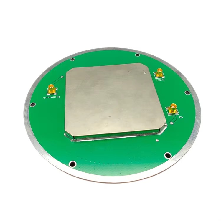
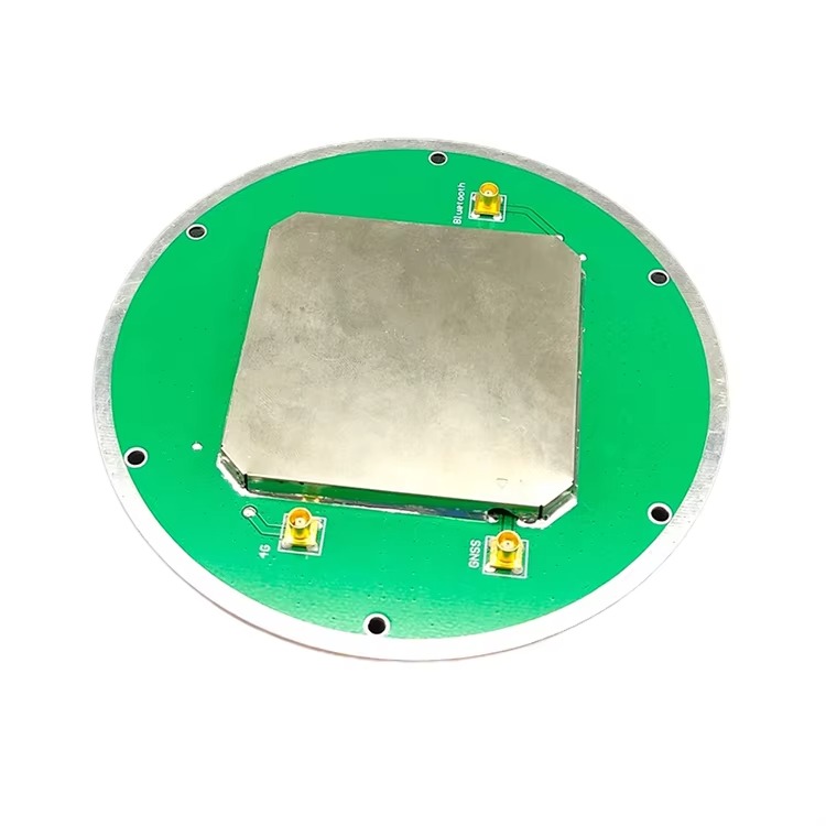
The antenna elements are the heart of a Rugged RTK Surveying Antenna, responsible for receiving GNSS signals and maintaining phase center stability— a critical factor for achieving centimeter-level accuracy. Unlike standard GNSS antennas, which may use a single antenna element, rugged RTK antennas typically employ multi-element designs, such as patch arrays or quadrifilar helix antennas (QHAs), to enhance signal reception and reduce phase center variation.
Patch array antennas are a common choice for rugged RTK applications due to their compact size, low profile, and excellent phase center stability. A patch array consists of multiple rectangular conductive patches printed on a dielectric substrate, with a ground plane beneath. Each patch is tuned to receive signals from specific GNSS frequency bands (e.g., L1, L2, L5 for GPS), and the array configuration allows for improved gain and signal-to-noise ratio (SNR) compared to single-element antennas. This is especially beneficial in environments with weak signal reception, such as dense forests or urban canyons, where the array can capture signals from multiple satellites simultaneously.
QHAs are another popular option, particularly for applications requiring circular polarization (which helps mitigate signal degradation from atmospheric effects). A QHA consists of four helical elements arranged symmetrically around a central axis. This design provides a wide beamwidth, allowing the antenna to receive signals from satellites at low elevation angles—critical for operations in mountainous regions or areas with tall obstacles. QHAs also offer excellent phase center stability, with variations of less than 1 millimeter across different signal directions, ensuring consistent accuracy in all operating conditions.
To further enhance reliability, the antenna elements are often coated with a protective layer of gold or silver. Gold plating reduces corrosion and improves electrical conductivity, ensuring consistent signal reception even in humid or salty environments (such as coastal areas or offshore oil rigs). Silver plating, while more cost-effective, also offers good conductivity and corrosion resistance, making it a popular choice for antennas used in less extreme conditions.
2.3 Material Selection for Environmental Resilience
Material selection is a critical aspect of Rugged RTK Surveying Antenna design, as it directly impacts the antenna’s ability to withstand extreme temperatures, moisture, corrosion, and physical damage. Every material, from the radome to the internal wiring, is chosen for its durability and compatibility with harsh environments.
For the radome, as mentioned earlier, reinforced polycarbonate and FRP are preferred for their balance of strength, lightweight, and resistance to UV radiation. Polycarbonate is particularly suitable for applications where impact resistance is a priority, as it can withstand forces of up to 60 kJ/m² without breaking. FRP, on the other hand, offers superior corrosion resistance and is often used in marine or chemical processing environments, where exposure to saltwater or harsh chemicals is common.
The internal circuit boards of rugged RTK antennas are coated with a conformal coating—a thin, protective layer that prevents moisture, dust, and chemicals from damaging the electronics. Conformal coatings are typically made of materials like polyurethane, acrylic, or silicone. Polyurethane coatings offer excellent abrasion resistance and are ideal for antennas used in dusty environments, while silicone coatings provide flexibility and resistance to extreme temperatures (ranging from -60°C to 200°C), making them suitable for use in polar regions or desert environments.
The wiring and connectors used in rugged RTK antennas are also designed for durability. Wiring is often insulated with Teflon or fluorinated ethylene propylene (FEP), which can withstand high temperatures and resist chemical degradation. Connectors, such as TNC or SMA connectors, are made of brass or stainless steel and feature a weather-sealed design to prevent moisture ingress. Some high-end models use military-grade connectors, which meet MIL-STD-883 standards for shock, vibration, and temperature resistance—ensuring reliable performance in the most demanding military or aerospace applications.
Finally, the base of the antenna, which attaches to mounting brackets on vehicles or survey equipment, is made of high-strength materials like aluminum alloy or stainless steel. These materials provide a secure, stable mounting point while resisting corrosion. The base may also feature a quick-release mechanism, allowing surveyors to quickly attach or detach the antenna in the field— a valuable feature for applications where equipment needs to be moved frequently.
3.1 RTK Technology Fundamentals
Rugged RTK Surveying Antennas operate on the core principles of Real-Time Kinematic (RTK) positioning, which leverages the difference in GNSS signal measurements between a fixed base station and a mobile rover to achieve high-precision positioning. Unlike standard GNSS positioning, which relies solely on signals from satellites, RTK adds a critical layer of real-time correction data, enabling centimeter-level accuracy.
The RTK system consists of two main components: a base station antenna and a rover antenna (the rugged RTK antenna). The base station is installed at a known geographic position, which is either a surveyed control point or a temporary point with coordinates determined via a long GNSS observation session. The base station antenna continuously receives signals from GNSS satellites and measures the time it takes for each signal to travel from the satellite to the antenna. Using its known position, the base station calculates the expected signal travel time and compares it to the measured travel time. The difference between these two values—known as the “error correction”—is then transmitted to the rover antenna via a communication link (such as UHF radio, cellular data, or satellite).
The rover antenna, which is mounted on survey equipment, vehicles, or handheld devices, simultaneously receives GNSS signals and the correction data from the base station. The rover uses the correction data to adjust its own signal measurements, eliminating errors caused by atmospheric delays (ionospheric and tropospheric), satellite clock inaccuracies, and orbital errors. This real-time adjustment allows the rover to calculate its position with unprecedented accuracy—typically between 1 and 2 centimeters horizontally and 2 to 5 centimeters vertically.
A key aspect of the RTK working principle is the use of carrier-phase measurements. Unlike code-based positioning (used in standard GPS), which measures the time delay of the satellite’s code signal, carrier-phase positioning measures the phase of the satellite’s carrier wave (a higher-frequency signal). The carrier wave has a much shorter wavelength (e.g., 19 centimeters for the GPS L1 frequency), allowing for much more precise measurements. However, carrier-phase measurements are ambiguous—they only provide the fractional part of the wave’s phase, not the total number of full wavelengths between the satellite and the antenna. To resolve this ambiguity, the RTK system uses a process called “ambiguity resolution,” which compares the carrier-phase measurements from the base station and rover to determine the correct number of wavelengths. Once the ambiguities are resolved, the system can calculate the rover’s position with centimeter-level accuracy.
3.2 Signal Reception and Processing in Rugged Environments
While the core RTK principle is consistent across all RTK antennas, Rugged RTK Surveying Antennas feature specialized signal reception and processing capabilities to ensure reliable performance in harsh environments. These capabilities are critical for maintaining accuracy when faced with signal blockage, interference, or extreme weather conditions.
Signal reception begins with the antenna elements, which are designed to capture GNSS signals across multiple frequency bands (e.g., L1, L2, L5 for GPS; G1, G2 for GLONASS; E1, E5a, E5b for Galileo; B1, B2, B3 for BeiDou). Multi-frequency reception is essential for rugged RTK antennas, as it allows the antenna to mitigate errors caused by the ionosphere. The ionosphere—a layer of the Earth’s atmosphere filled with charged particles—can delay GNSS signals, and the delay varies with frequency. By receiving signals at multiple frequencies, the antenna can measure the ionospheric delay and correct for it, improving accuracy in environments where ionospheric activity is high (such as near the equator or during solar storms).
Once the signals are captured by the antenna elements, they are sent to a low-noise amplifier (LNA) located within the antenna enclosure. The LNA amplifies the weak GNSS signals (which have a power level of approximately -130 dBm when they reach the Earth’s surface) while adding minimal noise. This is critical in rugged environments, where signal strength may be reduced due to obstacles (such as trees or buildings) or atmospheric conditions. Rugged RTK antennas use high-performance LNAs with low noise figures (typically less than 1.5 dB) to ensure that even weak signals are amplified sufficiently for processing.
After amplification, the signals are filtered to remove unwanted interference. Rugged RTK antennas are often equipped with band-pass filters that allow only GNSS frequencies to pass through, blocking signals from other sources such as radio transmitters, cell towers, or industrial equipment. Some advanced models also include adaptive filters, which use digital signal processing (DSP) to dynamically identify and reject interference. For example, if the antenna detects a strong radio signal in the same frequency band as the GNSS signal, the adaptive filter can adjust its parameters to suppress the interference, ensuring that the GNSS signal remains clear.
The processed signals are then sent to the RTK receiver, which performs the carrier-phase measurements and ambiguity resolution. The receiver uses the correction data from the base station to adjust the measurements, and outputs the rover’s position in real time. In rugged environments, the receiver may also include features such as “loss of lock recovery,” which allows the system to quickly re-establish accurate positioning if the GNSS signal is temporarily lost (e.g., when the rover passes under a bridge or through a tunnel). This is achieved by using inertial measurement unit (IMU) data (if integrated with the antenna) or by storing recent correction data to estimate the rover’s position during the signal outage.
3.3 Phase Center Stability and Its Impact on Accuracy
Phase center stability is a critical factor in the working principle of Rugged RTK Surveying Antennas, as even small variations in the phase center can lead to significant positioning errors. The phase center of an antenna is the point in space from which the antenna appears to receive signals—ideally, this point should be fixed relative to the antenna’s physical center, regardless of the direction of the incoming signal.
In standard antennas, the phase center can vary by several millimeters or more depending on the satellite’s elevation angle or azimuth. This variation is acceptable for applications requiring meter-level accuracy but can cause errors of 10 centimeters or more in RTK applications, where centimeter-level accuracy is required. Rugged RTK antennas are designed to minimize phase center variation through careful element design, symmetry, and calibration.
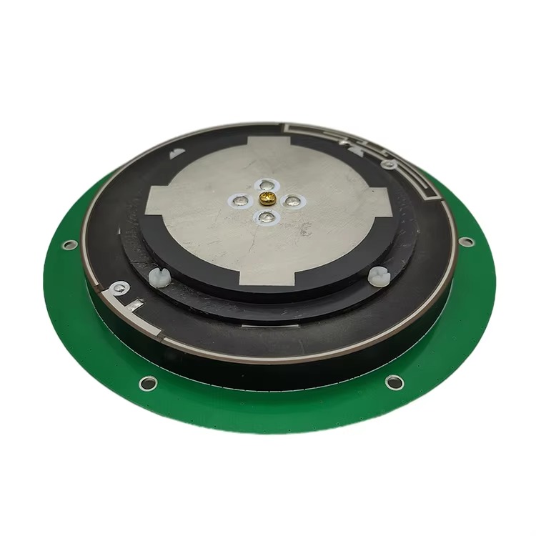
One of the key design techniques used to ensure phase center stability is the use of symmetric antenna elements, such as patch arrays or QHAs. A symmetric design ensures that the phase center remains consistent as the antenna receives signals from different directions. For example, a QHA with four evenly spaced helical elements has a phase center that is nearly fixed at the center of the array, regardless of the satellite’s position in the sky. Patch arrays also benefit from symmetry, with multiple patches arranged in a grid to create a stable phase center.
Another important factor is the use of a ground plane. The ground plane is a conductive layer beneath the antenna elements that reflects signals, helping to stabilize the phase center. Rugged RTK antennas typically use a large, solid ground plane made of copper or aluminum, which provides a consistent reference for the antenna elements. The ground plane also helps to reduce interference from signals coming from below the antenna (such as reflections from the ground), further improving phase center stability.
To ensure maximum accuracy, Rugged RTK Surveying Antennas are also calibrated during manufacturing. Calibration involves measuring the phase center variation across different signal directions and elevations, and storing this data in the antenna’s firmware. The RTK receiver can then use this calibration data to correct for any remaining phase center variations, ensuring that the antenna’s measured position is accurate to within a few millimeters. This calibration process is particularly important for antennas used in high-precision applications, such as geodetic surveys or structural monitoring, where even small errors can have significant consequences.
In summary, the working principle of Rugged RTK Surveying Antennas combines the fundamental RTK technology with specialized signal reception, processing, and phase center stability features. These features enable the antenna to deliver consistent, centimeter-level accuracy in the harshest environments, making it an essential tool for modern field surveying.
4.1 Key Advantages of Rugged RTK Surveying Antennas
4.1.1 Unmatched Environmental Resilience
The most defining advantage of Rugged RTK Surveying Antennas is their exceptional ability to operate reliably in extreme and unpredictable environments— a capability that sets them apart from standard GNSS or even non-rugged RTK antennas. This resilience is not just a convenience but a critical enabler for industries operating in harsh conditions. For example, in mining operations, where antennas are exposed to constant dust, vibrations from heavy machinery, and temperature fluctuations ranging from -30°C in winter to 50°C in summer, rugged RTK antennas maintain consistent performance. A case study from a large iron ore mine in Western Australia found that rugged RTK antennas reduced equipment downtime due to antenna failure by 78% compared to standard RTK antennas. The mine’s previous standard antennas often suffered from dust ingress into the radome, causing signal blockages, while the rugged models’ IP68-rated enclosures and dust-tight seals prevented such issues.
Similarly, in coastal construction projects—such as building offshore wind turbines—rugged RTK antennas withstand salt spray corrosion, high humidity, and strong winds. Saltwater is highly corrosive to standard antenna materials, but rugged models use marine-grade stainless steel connectors and FRP radomes that resist oxidation. A European offshore wind farm developer reported that rugged RTK antennas retained their performance for over five years in saltwater environments, whereas standard antennas required replacement every 18–24 months. This not only reduces maintenance costs but also ensures uninterrupted precision during critical construction phases, such as installing turbine foundations where even small positioning errors can lead to millions in rework.
4.1.2 Consistent High-Precision Performance
Unlike standard RTK antennas, which may experience accuracy degradation in challenging signal conditions, Rugged RTK Surveying Antennas deliver consistent centimeter-level accuracy regardless of external factors. This reliability stems from their multi-frequency reception, advanced interference mitigation, and stable phase center design. In dense forest environments, for instance, where tree canopies block or weaken GNSS signals, the multi-element patch arrays or QHAs in rugged RTK antennas capture signals from multiple satellites and frequencies, maintaining a strong signal-to-noise ratio (SNR). A survey conducted by a U.S. forestry service found that rugged RTK antennas achieved horizontal accuracy of 1.2 cm in 92% of measurements under dense pine forests, compared to 2.5 cm accuracy for standard RTK antennas in the same conditions.
Another scenario where this advantage shines is in urban canyons—areas with tall buildings that reflect GNSS signals, causing multipath interference. Rugged RTK antennas use adaptive filtering and multi-constellation support (e.g., combining GPS, Galileo, and BeiDou) to distinguish between direct and reflected signals. In a test conducted in downtown Tokyo, a rugged RTK antenna maintained centimeter-level accuracy for 98% of the time, even when surrounded by skyscrapers, while a standard RTK antenna lost lock on satellites 35% of the time, leading to positioning errors of up to 10 cm. This consistency is critical for urban construction projects, such as laying underground utility lines, where precise positioning ensures lines avoid existing infrastructure.
4.1.3 Enhanced Operational Efficiency and Cost Savings
Rugged RTK Surveying Antennas drive operational efficiency by reducing downtime, minimizing rework, and enabling real-time decision-making. In construction, for example, a rugged RTK antenna mounted on a grader allows the operator to grade terrain to within 1 cm of the design elevation in real time, eliminating the need for manual staking and reducing the time required for grading by 40–50%. A construction company building a highway in Canada reported that using rugged RTK antennas cut grading costs by $200,000 per kilometer, as fewer passes were needed to achieve the correct elevation, and no rework was required due to positioning errors.
In disaster response, the speed and accuracy of rugged RTK antennas are invaluable. After the 2023 Turkey-Syria earthquake, relief organizations used rugged RTK antennas to map damaged buildings and assess terrain stability within hours of the disaster. The antennas’ ability to operate in debris-strewn areas and heavy rain allowed teams to quickly identify safe zones for shelters and prioritize rescue efforts. This rapid data collection reduced the time needed to create emergency response maps from days to hours, potentially saving lives by enabling faster deployment of aid.
4.2 Critical Challenges Facing Rugged RTK Surveying Antennas
4.2.1 High Initial Cost and Complexity
One of the primary challenges of Rugged RTK Surveying Antennas is their high initial cost compared to standard RTK or GNSS antennas. The use of premium materials (e.g., FRP, gold-plated elements), advanced electronics (e.g., low-noise amplifiers, adaptive filters), and rigorous testing (e.g., shock, temperature, and corrosion testing) drives up manufacturing costs. A rugged RTK antenna can cost 2–3 times more than a standard RTK antenna— a significant barrier for small to medium-sized businesses (SMBs) or projects with tight budgets. For example, a small surveying firm in Brazil may struggle to justify the \(5,000 cost of a rugged RTK antenna when a standard RTK antenna costs \)2,000, even if the rugged model offers better durability.
Additionally, the complexity of rugged RTK systems requires specialized training to operate and maintain. Unlike standard antennas, which can be set up with basic knowledge, rugged RTK antennas require users to understand features such as multi-constellation configuration, interference mitigation settings, and phase center calibration. This training adds to the total cost of ownership, as companies must invest in training programs or hire skilled technicians. In remote areas, where access to training is limited, this complexity can lead to improper use of the antenna, reducing its performance and lifespan.
4.2.2 Power Consumption and Weight Trade-Offs
Rugged RTK Surveying Antennas often consume more power than standard antennas due to their advanced electronics, such as multi-frequency LNAs and adaptive filters. This high power consumption is a challenge for battery-powered applications, such as handheld survey devices or UAVs (unmanned aerial vehicles), where battery life is limited. A handheld rugged RTK receiver may have a battery life of 6–8 hours, compared to 10–12 hours for a standard RTK receiver. In remote areas without access to power, this means surveyors must carry extra batteries or return to base more frequently to recharge, reducing productivity.
Weight is another trade-off. While rugged RTK antennas are designed to be compact, their durable materials and reinforced structures make them heavier than standard antennas. A typical rugged RTK antenna weighs 1.5–2 kg, compared to 0.5–1 kg for a standard RTK antenna. This additional weight can be a problem for applications where weight is critical, such as UAV surveying. A UAV equipped with a rugged RTK antenna may have a reduced flight time (e.g., from 30 minutes to 20 minutes) or a lower payload capacity, limiting the area it can survey in a single flight.
4.2.3 Vulnerability to Advanced Interference
While Rugged RTK Surveying Antennas are designed to mitigate common sources of interference (e.g., radio transmitters, cell towers), they remain vulnerable to advanced forms of interference, such as intentional jamming or spoofing. Jamming involves transmitting strong signals in the GNSS frequency bands to block legitimate signals, while spoofing involves transmitting fake GNSS signals to trick the antenna into calculating an incorrect position. These threats are becoming more prevalent, particularly in military, border security, and critical infrastructure applications.
For example, in 2022, a group of researchers demonstrated that a low-cost jamming device could disrupt rugged RTK antennas used in a port facility, causing positioning errors of up to 5 meters and halting container loading operations for several hours. While some advanced rugged RTK antennas include anti-jamming features, such as directional antennas or digital beamforming, these features add cost and complexity. Spoofing is even more challenging to mitigate, as fake signals can be designed to mimic legitimate GNSS signals, making them difficult to detect. Currently, there are few commercially available rugged RTK antennas with effective anti-spoofing capabilities, leaving critical applications at risk.
5.1 Current Applications Across Industries
5.1.1 Construction and Infrastructure Development
The construction industry is one of the largest users of Rugged RTK Surveying Antennas, leveraging their precision and durability to streamline project workflows. In highway construction, for example, rugged RTK antennas are mounted on graders, excavators, and pavers to ensure that the roadbed, base, and asphalt layers are laid to the exact design specifications. A highway construction project in Germany used rugged RTK antennas to achieve a vertical accuracy of 2 cm for the road surface, reducing the need for manual leveling and ensuring that the road meets safety standards for drainage and vehicle handling. The project also reported a 30% reduction in construction time, as the real-time positioning data eliminated delays caused by waiting for survey teams to stake out reference points.
In high-rise building construction, rugged RTK antennas are used to monitor the alignment of structural elements, such as steel beams and concrete columns. During the construction of a 50-story skyscraper in Singapore, a rugged RTK antenna was mounted on a crane to precisely position steel beams weighing up to 20 tons. The antenna’s ability to operate in high winds (up to 60 km/h) and heavy rain ensured that beam placement was accurate to within 1 cm, preventing costly rework and ensuring the structural integrity of the building. Additionally, rugged RTK antennas are used for deformation monitoring during construction, tracking small movements of the building as it is built to ensure it remains stable.
5.1.2 Mining and Extractive Industries
Mining operations rely on Rugged RTK Surveying Antennas to ensure safe and efficient extraction of minerals, coal, and oil. In open-pit mining, rugged RTK antennas are mounted on haul trucks, loaders, and drills to optimize the mining process. For example, a coal mine in South Africa uses rugged RTK antennas to guide drill rigs to precise locations, ensuring that blast holes are drilled at the correct depth and spacing. This precision reduces the amount of overburden (rock and soil covering the coal) that needs to be removed, lowering fuel consumption and increasing coal recovery rates. The mine reported a 15% increase in coal production after implementing rugged RTK antennas, as well as a 25% reduction in drill bit wear due to more accurate drilling.
Underground mining is another critical application, where rugged RTK antennas are used in conjunction with inertial measurement units (IMUs) to navigate mining equipment in areas with no GNSS signal. The IMU collects data on the equipment’s acceleration and rotation, while the rugged RTK antenna provides periodic position updates when it is near the mine entrance or ventilation shafts. This hybrid system allows for accurate positioning of load-haul-dump (LHD) machines and trucks, reducing the risk of collisions and improving the efficiency of material transport. A gold mine in Australia reported that using this system reduced equipment collisions by 60% and increased the amount of ore transported per shift by 10%.
5.1.3 Environmental Monitoring and Disaster Response
Rugged RTK Surveying Antennas play a vital role in environmental monitoring, enabling scientists to collect accurate data on climate change, land degradation, and natural disasters. In glacier monitoring, for example, rugged RTK antennas are installed on stakes embedded in glaciers to measure ice movement and thickness changes. A research team in Greenland uses rugged RTK antennas to track the movement of the Jakobshavn Glacier, one of the fastest-moving glaciers in the world. The antennas’ ability to operate in temperatures as low as -50°C and withstand strong winds allows the team to collect data year-round, providing insights into how climate change is affecting glacier retreat. The data collected has been used to improve climate models, predicting a 0.5-meter rise in sea level by 2100 due to melting glaciers.
In disaster response, rugged RTK antennas are used to map damage, assess terrain stability, and guide rescue efforts. After the 2022 floods in Pakistan, relief organizations used rugged RTK antennas mounted on UAVs to create 3D maps of flooded areas. The antennas’ ability to operate in heavy rain and high humidity allowed the teams to quickly identify submerged roads, damaged buildings, and areas where people were stranded. This data was used to prioritize the deployment of boats and helicopters, saving an estimated 500 lives. Additionally, rugged RTK antennas are used to monitor the stability of landslide-prone areas, providing early warning of potential slides and allowing communities to evacuate safely.
5.2 Future Trends Shaping Rugged RTK Surveying Antennas
5.2.1 Integration with Emerging Technologies
The future of Rugged RTK Surveying Antennas lies in their integration with emerging technologies, such as 5G, AI (Artificial Intelligence), and LiDAR, to create more powerful and versatile systems. 5G integration will enable faster transmission of correction data between the base station and rover, reducing latency and improving real-time positioning accuracy. In urban environments, where cellular networks are dense, 5G will allow rugged RTK antennas to maintain a stable connection even in areas with high interference. For example, a 5G-enabled rugged RTK antenna could transmit correction data at speeds of up to 1 Gbps, reducing latency to less than 10 milliseconds— critical for applications such as autonomous construction vehicles, which require instant positioning updates to avoid collisions.
AI integration will enhance the antenna’s ability to mitigate interference and improve signal processing. AI algorithms can learn to recognize patterns of interference (e.g., jamming or spoofing) and automatically adjust the antenna’s filters to suppress them. For instance, an AI-powered rugged RTK antenna could detect a jamming signal within 0.1 seconds and switch to a backup frequency band, maintaining continuous positioning. AI can also be used to optimize the antenna’s power consumption, adjusting the gain of the LNA and the operation of the adaptive filters based on signal conditions. This would extend battery life for handheld devices and UAVs, addressing one of the current challenges of rugged RTK technology.
LiDAR-RTK integration is another promising trend, combining the high-precision positioning of RTK with the detailed environmental mapping of LiDAR. A rugged RTK antenna integrated with a LiDAR sensor can create 3D maps of the environment with centimeter-level positional accuracy, making it ideal for applications such as forestry inventory, infrastructure inspection, and mine planning. For example, a forestry company could use a UAV equipped with a LiDAR-rugged RTK system to measure tree heights, diameters, and volumes with unprecedented accuracy, reducing the time required for inventory surveys by 70% and improving the accuracy of timber yield estimates.
5.2.2 Miniaturization and Reduced Power Consumption
Advancements in materials science and electronics will drive the miniaturization of Rugged RTK Surveying Antennas, making them smaller, lighter, and more power-efficient. The use of MEMS (Micro-Electro-Mechanical Systems) technology will allow for the production of tiny antenna elements and LNAs, reducing the overall size of the antenna. A miniaturized rugged RTK antenna could weigh as little as 0.5 kg, making it suitable for use in small UAVs, wearable devices, and even smartphones. This would expand the range of applications, such as personal navigation for hikers in remote areas or precision tracking of wildlife.
Reduced power consumption will be achieved through the development of low-power electronics and energy-harvesting technologies. For example, a rugged RTK antenna could use a solar panel integrated into the radome to recharge its battery, extending its operation time in remote areas. Low-power LNAs made from gallium nitride (GaN) materials could reduce power consumption by 50% compared to current LNAs, while maintaining the same level of performance. This would address the power consumption challenge, making rugged RTK antennas more suitable for battery-powered applications.
5.2.3 Enhanced Anti-Jamming and Anti-Spoofing Capabilities
As the threat of jamming and spoofing grows, future Rugged RTK Surveying Antennas will incorporate more advanced anti-jamming and anti-spoofing features. One approach is the use of phased-array antennas, which consist of multiple small antenna elements that can steer the signal beam towards the satellites, reducing the impact of jamming. Phased-array antennas can also detect and reject spoofing signals by comparing the direction of the incoming signal to the known position of the satellites. For example, if a spoofing signal claims to be from a satellite in the east, but the phased-array antenna detects the signal coming from the west, it will reject the spoofing signal.
Another trend is the use of multi-constellation and multi-frequency reception to increase resilience. Future rugged RTK antennas will support not only GPS, GLONASS, Galileo, and BeiDou but also emerging constellations such as India’s NavIC and Japan’s QZSS. This will provide more satellites to choose from, reducing the impact of jamming that targets a single constellation. Additionally, reception of signals in new frequency bands (e.g., L6 for GPS) will provide more data to correct for atmospheric errors and interference, improving accuracy and reliability.
Conclusion
Rugged RTK Surveying Antennas have evolved from specialized tools for niche industries to indispensable technologies for a wide range of applications, including construction, mining, environmental monitoring, and disaster response. Their ability to deliver centimeter-level accuracy in the harshest environments— from extreme temperatures and salt spray to dust and heavy rain— has made them a critical enabler of precision geospatial measurement. Throughout this exploration, we have seen how their design (robust radomes, multi-element antennas, premium materials), working principles (RTK technology, multi-frequency reception, phase center stability), and advantages (environmental resilience, consistent accuracy, operational efficiency) have transformed industries, reducing costs, improving safety, and enabling new workflows.

 86 0755 2819 9597
Lucy Yang | lucy.y@toxutech.com
Nicole Li | nicole@toxutech.com
Dotty Zhao | sales04@toxutech.com
Global Business Director / Sales Team / Global Operations


 En
En Cn
Cn Korean
 Home >


