

-
Products -PCBA Manufacturing RF Connectors RF Cable Assemblys Embedded Antennas External Antennas Positioning Chips and Modules
RF Connectors

RF Cable Assemblys
Embedded Antennas
External Antennas
Positioning Chips and Modules


 Language


Language


The Global Navigation Satellite System (GNSS) is a collective term for satellite - based navigation systems that provide location, velocity, and time (PVT) information to users worldwide. Prominent constellations within GNSS include the United States' Global Positioning System (GPS), Russia's GLONASS, the European Union's Galileo, and China's BeiDou Navigation Satellite System, among others. These systems have revolutionized navigation and positioning applications across various industries.
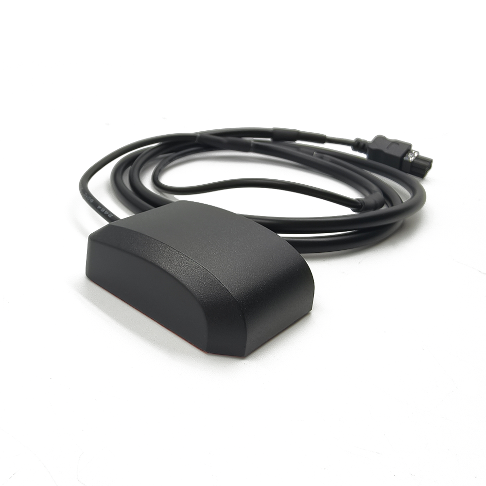
A rugged GNSS external antenna is a specialized, passive or active radio frequency (RF) device designed to optimally receive very low-power signals from GNSS satellites across multiple frequency bands. Its "ruggedized" designation distinguishes it from consumer-grade antennas through its enhanced durability, environmental protection, and consistent performance under the most demanding operational conditions. While a smartphone or a standard car navigation system might have a small, embedded antenna sufficient for casual use, these are wholly inadequate for applications where accuracy, availability, and integrity are mission-critical.
The core mission of a rugged antenna is threefold:
Maximize Signal Reception: To capture the extremely weak GNSS signals (often compared to trying to see a 25-watt lightbulb from 12,000 miles away) with high efficiency.
Minimize Interference: To reject unwanted signals, such as noise from nearby electronic equipment (jamming) or deliberate deception (spoofing), and multipath signals (reflections from the ground or structures).
Ensure Continuous Operation: To perform these functions consistently while exposed to physical shock, vibration, extreme temperatures, moisture, salt fog, UV radiation, and chemical exposure.
The applications for such robust hardware are vast and varied. They form the backbone of safety-critical systems in aviation, where approach and landing procedures demand unwavering precision. They guide autonomous farm equipment across vast fields with centimeter-level accuracy for precision agriculture. They enable the relentless pace of modern logistics, tracking container ships across oceans and heavy machinery within ports. In the military and public safety domains, they provide reliable positioning for personnel, vehicles, and unmanned systems in environments where failure is not an option. Furthermore, they are indispensable in scientific fields like geodesy, seismology, and meteorology, where they help measure tectonic plate movements and atmospheric water vapor content.
In essence, the rugged external antenna is the unsung hero of high-precision GNSS. It is the foundational element that transforms a theoretical capability into a practical, reliable tool. Without a high-performance antenna to faithfully acquire the satellite signals, even the most advanced and expensive GNSS receiver processor cannot compute an accurate position. The antenna's design, construction, and placement are, therefore, the first and most crucial determinants of overall system performance. It is the gateway through which all positioning data must pass, and its robustness ensures that this gateway remains open, regardless of the challenges posed by the environment or the application.
The design and construction of a rugged GNSS antenna is a sophisticated exercise in electromagnetic engineering, materials science, and mechanical design. Every element, from the radiating element itself to the external housing, is meticulously chosen and engineered to achieve a specific performance characteristic while surviving harsh conditions. The process balances often-competing demands of electrical efficiency, bandwidth, physical durability, and cost.
The Radiating Element: The Heart of the Antenna
At the core of any antenna is its radiating element, the structure responsible for converting electromagnetic waves into electrical currents and vice-versa. For GNSS antennas, the most common type is the patch antenna. This is a flat, square or circular conductor mounted over a ground plane. Its popularity stems from its low profile, reliable hemispherical coverage (ideal for receiving signals from satellites above the horizon), and ease of manufacture. Modern high-precision patch antennas are often multilayer designs, incorporating multiple resonators to achieve wide bandwidth coverage across all major GNSS bands (L1, L2, L5, etc.).
For applications requiring even higher performance, particularly in rejecting multipath signals arriving from low elevations, choke-ring antennas are employed. These incorporate a series of concentric, corrugated metal rings surrounding the patch element. These rings act as a ground plane that becomes increasingly inefficient at lower elevation angles, effectively "choking" out signals coming from near the horizon, which are more likely to be multipath reflections. While larger, heavier, and more expensive, choke rings are the gold standard for geodetic and scientific reference stations.
The Feed Network and Amplification
Behind the radiating patch lies the feed network, a delicate pattern of microstrip lines that properly distributes the signal. For antennas that cover multiple frequencies (e.g., GPS L1 and L5), this network must carefully combine the signals from different ports on the patch without causing phase distortions.
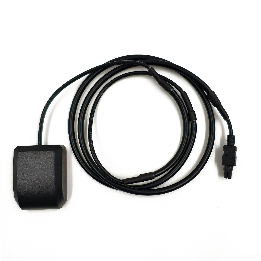
Most modern GNSS antennas are active antennas, meaning they incorporate a Low-Noise Amplifier (LNA) directly within the antenna housing. This is critical because GNSS signals are incredibly weak by the time they reach the Earth's surface and suffer losses as they travel through the coaxial cable to the receiver. The LNA's primary job is to amplify the desired signal while adding as little inherent electronic noise as possible, a quality measured by its Noise Figure. A good LNA might have a noise figure of 1-2 dB. By amplifying the signal at the source (the antenna), the system can overcome cable losses and improve the overall signal-to-noise ratio (SNR) delivered to the receiver. Active antennas require power, which is almost universally supplied through the same coaxial cable that carries the signal, using a scheme called DC power over coax or bias-teeing.
Environmental Protection and Housing
The housing is what makes an antenna "rugged." It must protect the delicate internal electronics from a host of environmental threats.
Material: Housings are typically made from high-grade engineering plastics like polycarbonate or ABS, often with additives for UV stability to prevent degradation and brittleness from sun exposure. For extreme mechanical demands, metal housings (e.g., aluminum) are used, though they require careful design to avoid shielding the antenna element.
Sealing: To prevent ingress of moisture and dust, rugged antennas are sealed using high-quality gaskets (often silicone) and are rated using the Ingress Protection (IP) code. A rating of IP67 (dust-tight and protected against immersion in water up to 1m for 30 minutes) is common, with IP68 and IP69K (high-pressure, high-temperature water jets) for the most severe environments.
Radome: The protective cover over the radiating element, the radome, must be transparent to GNSS radio frequencies. It is typically made from materials like polyetherimide (PEI) or ceramic-filled plastics that have stable dielectric properties and low loss tangents across the required frequency spectrum. The shape of the radome is also engineered to minimize signal distortion.
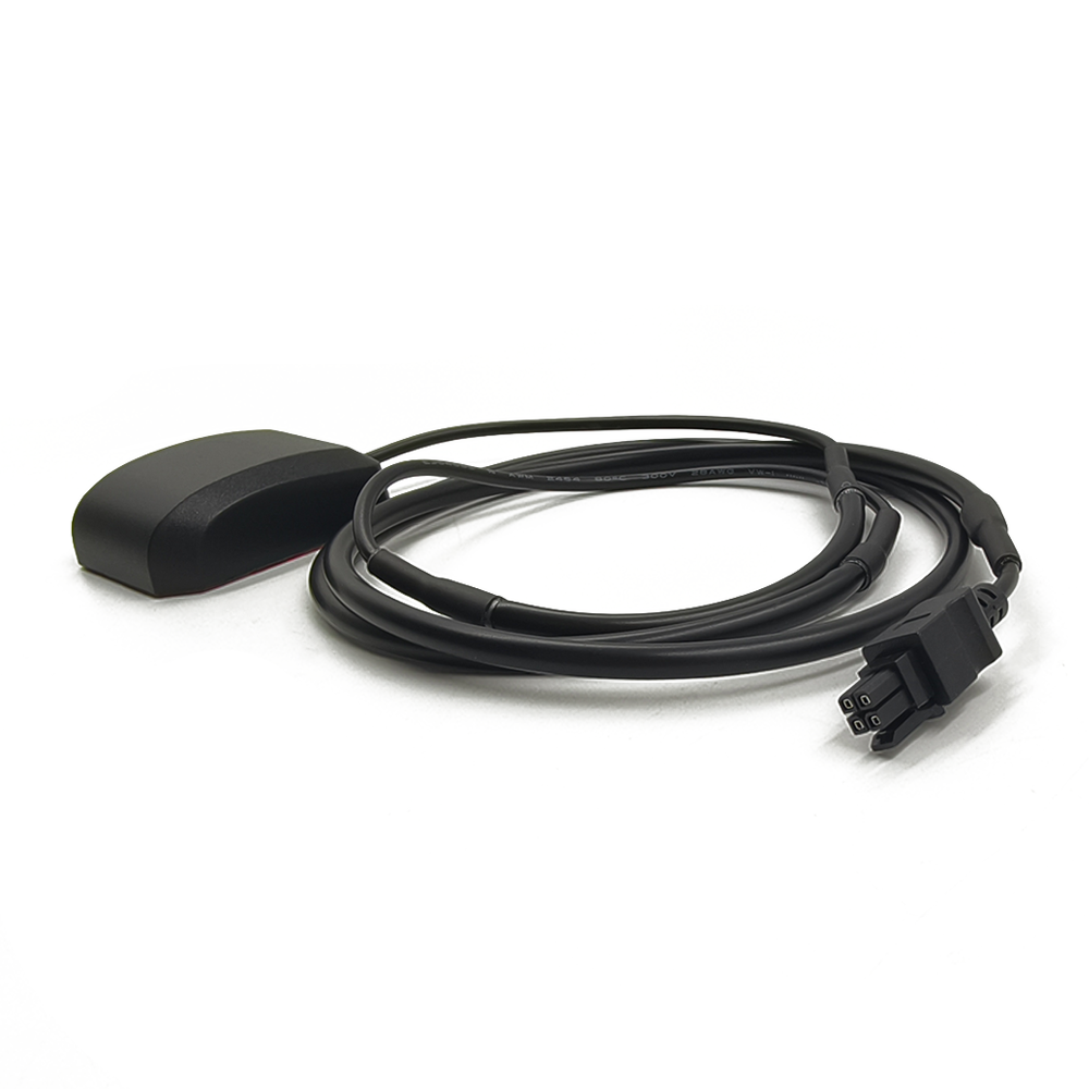
Mounting and Connectivity
Rugged antennas are designed for permanent installation. Standard mounting options include magnetic bases (for temporary or vehicle-mounted use), flush mounts (for low-profile installation on vehicle roofs), and pole mounts (for fixed reference stations). The connector is a critical, often overlooked component. Standard TNC and SMA connectors are common, but N-type connectors are preferred for professional applications due to their superior weatherproofing, durability, and lower signal loss, especially at higher frequencies. All external connectors and cables must be properly weatherproofed to complete the system's environmental seal.
In summary, the construction of a rugged GNSS antenna is a holistic process where electrical performance cannot be divorced from mechanical and environmental robustness. It is a sealed, amplified, and protected system engineered to provide a clean, strong signal to the receiver, day in and day out, from the frozen Arctic to the scorching desert.
The operation of a rugged GNSS external antenna is a fascinating process that involves principles of electromagnetism, electronics, and signal processing. Its primary function is to act as a transducer, but its role is far more nuanced than simply "catching a signal." Understanding its working principles reveals why its design is so critical.
Fundamental Electromagnetic Reception
GNSS satellites broadcast spread-spectrum signals in the L-band of the radio spectrum (approximately 1 to 2 GHz). These signals are right-hand circularly polarized (RHCP). The antenna's radiating element (the patch) is specifically designed to be most sensitive to this type of polarization. This design choice provides an inherent advantage: many natural and man-made reflected signals become left-hand circularly polarized (LHCP) or linearly polarized upon reflection. The RHCP antenna is therefore naturally less sensitive to these multipath signals, providing a first layer of filtering.
When the RHCP radio wave impinges upon the patch antenna, it induces a tiny, oscillating electric current in the conductive material. The dimensions of the patch are precisely calculated to be a resonant length for the target GNSS frequencies (e.g., ~19mm for the GPS L1 frequency of 1575.42 MHz). This resonance means the antenna efficiently converts the energy of the passing electromagnetic wave into an electrical current at its feed point.
Bandwidth and Multi-Frequency Operation
Modern high-precision GNSS requires signals from multiple frequency bands. The ionosphere, a layer of charged particles in the upper atmosphere, delays GNSS signals by an amount inversely proportional to the square of the signal's frequency. By receiving the same navigation message on two different frequencies (e.g., L1 and L2), a dual-frequency receiver can calculate and correct for this ionospheric delay, a major source of error.
A rugged antenna must therefore have sufficient bandwidth to cover these multiple frequencies without significant variation in its performance characteristics, particularly its phase center.
The Phase Center: The Antenna's True "Point"
The phase center is the perceived point in space from which the signal appears to originate. It is a critical concept for high-precision applications. An ideal antenna would have a phase center that is stable and does not vary with the elevation or azimuth of the incoming satellite signal. In reality, all antennas have a certain amount of phase center variation (PCV). For a rugged geodetic antenna, these variations are meticulously measured in an anechoic chamber and provided as a calibration table (e.g., ANTEX file). The receiver or post-processing software can then use this table to correct measurements, ensuring accuracy at the millimeter level. The stability of the phase center is a key differentiator between a consumer and a professional-grade antenna.
Low-Noise Amplification (LNA)
The electrical current generated at the antenna's feed point is extraordinarily weak, typically around -130 dBm (decibels relative to one milliwatt). This signal would be decimated by the loss in the coaxial cable running to the receiver. A meter of cable can easily introduce 0.5 dB of loss, which directly degrades the signal-to-noise ratio.
The integrated LNA solves this problem. It provides significant gain (often 25-40 dB), boosting the signal well above the noise floor introduced by the subsequent cable and the receiver's own front-end. Crucially, the LNA must do this while adding minimal internal noise of its own (low Noise Figure). By amplifying the signal at the source, the system effectively makes the cable loss irrelevant, as the signal is already strong before the loss occurs.
Filtering and Interference Mitigation
Many rugged antennas incorporate bandpass filters either before or after the LNA. These filters are designed to allow GNSS frequencies to pass through unhindered while attenuating strong out-of-band signals from other services like cellular (4G/5G), Wi-Fi, VHF/UHF radios, and radar. This filtering is essential to prevent these powerful signals from overloading the LNA or the receiver, causing desensitization or complete loss of lock on the GNSS signals. This is a vital feature in electromagnetically cluttered environments like ports, industrial sites, and urban areas.
In conclusion, the working principle of a rugged GNSS antenna is a continuous process of optimized signal capture, polarization filtering, minimal noise amplification, and out-of-band rejection. It transforms a faint, analog electromagnetic wave into a robust, amplified electrical signal, faithfully preserving the information encoded within it and ready for processing by the receiver to compute a precise position, velocity, and time (PVT) solution.
The deployment of a rugged GNSS external antenna offers a compelling array of advantages that are essential for professional and safety-critical applications. However, this enhanced performance and durability come with a set of inherent challenges and trade-offs that system integrators must carefully consider.
Advantages:
Superior Signal Quality and Reliability: This is the paramount advantage. The combination of a high-gain, precisely tuned radiating element and an integrated LNA results in a significantly higher Signal-to-Noise Ratio (SNR) and greater acquisition and tracking sensitivity. This translates directly to more reliable positioning, especially in challenging environments with partial sky view, such as urban canyons, under tree canopies, or in industrial settings.
Enhanced Multipath Rejection: Through careful design—using RHCP sensitivity, controlled antenna patterns, and advanced techniques like choke rings—rugged antennas are far more effective at rejecting signals reflected from the ground, buildings, and other obstacles. Multipath is a primary source of error in GNSS, and mitigating it at the antenna level is the most effective strategy.
Support for Multi-Constellation, Multi-Frequency (MCMF) Operations: Modern high-precision applications demand access to all satellites from all constellations (GPS, GLONASS, Galileo, BeiDou) across multiple frequencies (L1, L2, L2C, L5, E6, etc.). Rugged antennas are designed with wide bandwidth and stable phase characteristics to support this MCMF environment, future-proofing investments and enabling advanced error correction techniques like PPP-RTK.
Durability and Long-Term Stability: The investment in ruggedization pays dividends in longevity and reduced maintenance. The ability to withstand UV radiation, temperature cycling, moisture, salt spray, and physical abuse ensures that the antenna's performance remains consistent over years of operation. This reliability is non-negotiable for remote, unattended, or difficult-to-access installations.
Optimal Placement: An external antenna can be strategically placed on a vehicle or structure for the best possible sky view. It can be mounted on the highest point, away from sources of interference and multipath, a luxury not afforded to embedded antennas in devices that are often used sub-optimally (e.g., in a car cabin).
Challenges and Considerations:
Cost: Rugged antennas are significantly more expensive than their consumer-grade counterparts. The cost is driven by the precision engineering, high-quality materials (e.g., ceramic radomes, calibrated choke rings), rigorous testing, and the inclusion of specialized components like high-performance LNAs and filters. This can be a barrier to entry for cost-sensitive applications.
Size, Weight, and Power (SWaP): Performance often comes at the expense of SWaP. A high-performance choke-ring antenna can be large and heavy, making it unsuitable for small UAVs or portable equipment. Active antennas require a power source (typically 3-5V DC over the coax), which must be supplied by the receiver, adding a small but non-zero power draw to the system.
Integration Complexity: Installing an external antenna is more complex than using an embedded one. It requires careful routing of coaxial cable, proper weatherproofing of connectors, and selecting an appropriate mounting location. Poor installation can negate all the performance benefits of the antenna (e.g., a poor cable connection introducing loss or moisture).
Calibration Requirements: For the highest levels of precision (e.g., geodetic survey, scientific monitoring), the antenna's phase center variations must be known and corrected for. This requires using an antenna model with a publicly available calibration file (ANTEX). Not all antennas have this, and using an uncalibrated antenna for high-precision work can introduce systematic errors of several centimeters.
Susceptibility to Jamming and Spoofing: While filters help with out-of-band interference, a rugged antenna is just as susceptible to in-band jamming (overpowering real signals with noise) and spoofing (broadcasting counterfeit signals) as any other antenna. Mitigating these threats requires additional system-level solutions like controlled reception pattern antennas (CRPA), inertial navigation systems (INS), and advanced signal processing within the receiver.
In summary, the advantages of rugged antennas—unmatched reliability, accuracy, and durability—make them indispensable for professional use. However, their cost, size, and integration complexity present challenges that must be carefully weighed against the performance requirements of the specific application. The choice to use one is a conscious decision to prioritize data quality and system integrity over convenience and cost.
The unique capabilities of rugged GNSS antennas have unlocked a vast spectrum of applications that form the backbone of modern industry, science, and security. Furthermore, the field is dynamic, with several key trends shaping the future of antenna technology to meet the demands of emerging use cases.
Core Applications:
Geospatial and Surveying: This is the traditional home of high-precision GNSS. Rugged antennas, often paired with choke rings, are used on base stations and rover units to achieve centimeter-to-millimeter accuracy for cadastral mapping, construction site preparation, topographic surveys, and monitoring structural deformation of dams and bridges.
Agriculture (Precision Ag): Autonomous and semi-autonomous tractors and harvesters rely on rugged antennas for real-time kinematic (RTK) positioning to guide them with centimeter accuracy. This enables practices like variable rate application of seeds, fertilizer, and pesticides, maximizing yield and minimizing environmental impact.
Marine and Aviation: In maritime environments, corrosion-resistant rugged antennas are critical for navigation, dynamic positioning of vessels, and port automation. In aviation, they are certified for safety-of-life applications, enabling precision approach and landing systems like GBAS (Ground-Based Augmentation System) and supporting flight testing and aerial surveying.
Defense and Public Safety: Military operations depend on secure, reliable, and jamming-resistant PNT (Positioning, Navigation, and Timing). Rugged antennas are integrated into vehicles, aircraft, ships, and soldier systems. For firefighters and search-and-rescue teams, reliable GPS can be a matter of life and death in obscured visibility conditions.
Timing and Synchronization: The precise timing signals from GNSS are used to synchronize critical infrastructure. Rugged antennas are installed on cell phone towers to synchronize 4G/5G networks, on power grids to timestamp fault events, and in financial trading centers to timestamp transactions to the microsecond.
Autonomous Systems and Robotics: The rise of autonomy is perhaps the biggest driver. Unmanned Ground Vehicles (UGVs), Autonomous Guided Vehicles (AGVs) in warehouses, and Unmanned Aerial Vehicles (UAVs) all require continuous, reliable, and accurate positioning provided by rugged antennas integrated with IMUs and other sensors.
Future Trends:
Miniaturization and SWaP Optimization: The push for smaller, lighter, and lower-power antennas is relentless, driven by the proliferation of small UAVs, wearable devices, and the Internet of Things (IoT). Expect to see more advanced materials and design techniques (e.g., metamaterials) to shrink high-performance antennas without sacrificing capability.
Integrated Inertial Navigation Systems (INS): The fusion of GNSS and inertial sensors is becoming standard. The next step is the tighter integration of the antenna and the IMU into a single housing, ensuring a rigid and stable lever-arm between them, which simplifies system integration and improves overall navigation solution accuracy, especially during GNSS outages.
Advanced Interference Mitigation: As the RF spectrum becomes more crowded, antennas will need to become smarter. This includes the wider adoption of Controlled Reception Pattern Antennas (CRPAs or "steerable nulling antennas"), which can actively form nulls in their reception pattern in the direction of jammers while preserving gain towards satellites. This technology, once confined to military applications, is becoming more accessible for civil use.
Tightly Coupled Design for Automotive: For autonomous vehicles, the trend is towards "tightly coupled" GNSS/INS systems where the antenna is seamlessly integrated into the vehicle's roof or body styling, offering a clean aesthetic without compromising performance. These designs will need to maintain performance despite the challenging RF environment of a modern car.
Support for New Signals and Constellations: Antenna designers are already working on systems that can efficiently receive new signals, such as the high-powered L1C signal from GPS III satellites and the signals from LEO-PNT constellations (like Xona Space Systems). This will require even wider bandwidths and more sophisticated filtering techniques.
The future of rugged GNSS antennas is one of convergence: becoming smaller, smarter, and more deeply integrated into larger systems. They will evolve from being standalone components into intelligent sensor hubs that play an active role in ensuring resilient and assured PNT for the autonomous world.
Conclusion
In the intricate and invisible dance of global navigation, where signals traverse vast distances of space to inform us of our place on Earth, the rugged GNSS external antenna stands as the fundamental and critical gateway. This series has detailed its journey from an overview of its role to the depths of its design, principles, and applications. The conclusion is unequivocal: for any application where position, navigation, and timing (PNT) data transitions from being a convenience to a critical asset, the antenna is the non-negotiable foundation upon which all else is built.
It is the first element in the signal chain and, in many ways, the most important. No amount of advanced processing in the receiver can recover information that was lost or corrupted at the moment of reception. A rugged antenna's primary value is its role as a guarantor of signal integrity. It ensures that the faint whispers from satellites are captured with maximum efficiency, amplified with minimal distortion, and delivered to the receiver with the highest possible fidelity, all while actively defending against the myriad sources of error and interference that pervade the modern RF environment.
Its value is further cemented by its role as an enabler of resilience. The "rugged" moniker is not merely marketing; it is a promise of continuous operation. It is the assurance that a precision agriculture operation will not halt due to a dusty environment, that a survey marker's accuracy will not drift with the seasons, that a container ship will navigate a narrow channel safely in a storm, and that a first responder's location will be known even when their surroundings are hostile. This resilience provides system integrators and end-users with confidence—the confidence to deploy autonomous systems, to build critical infrastructure, and to undertake missions where failure is not an option.
The evolution of these antennas mirrors the evolution of technology itself, trending towards greater integration, intelligence, and miniaturization. They are becoming more than passive components; they are evolving into the first line of a sophisticated cyber-physical defense system against jamming and spoofing, and into a seamlessly integrated sensor within larger autonomous platforms.
Ultimately, selecting a GNSS antenna is a strategic decision. Opting for a consumer-grade solution is a calculation based on cost and convenience for non-critical applications. However, specifying a ruggedized external antenna is an investment in data quality, system reliability, and operational integrity. It is an acknowledgment that in the complex equation of precision positioning, the antenna is the most critical variable. It is the unsung hero on the front lines, the steadfast sentinel that never sleeps, ensuring that the world's ever-growing reliance on precise location and timing has a solid, dependable, and resilient foundation upon which to thrive.

 86 0755 2819 9597
Lucy Yang | lucy.y@toxutech.com
Nicole Li | nicole@toxutech.com
Dotty Zhao | sales04@toxutech.com
Global Business Director / Sales Team / Global Operations


 En
En Cn
Cn Korean
 Home >


