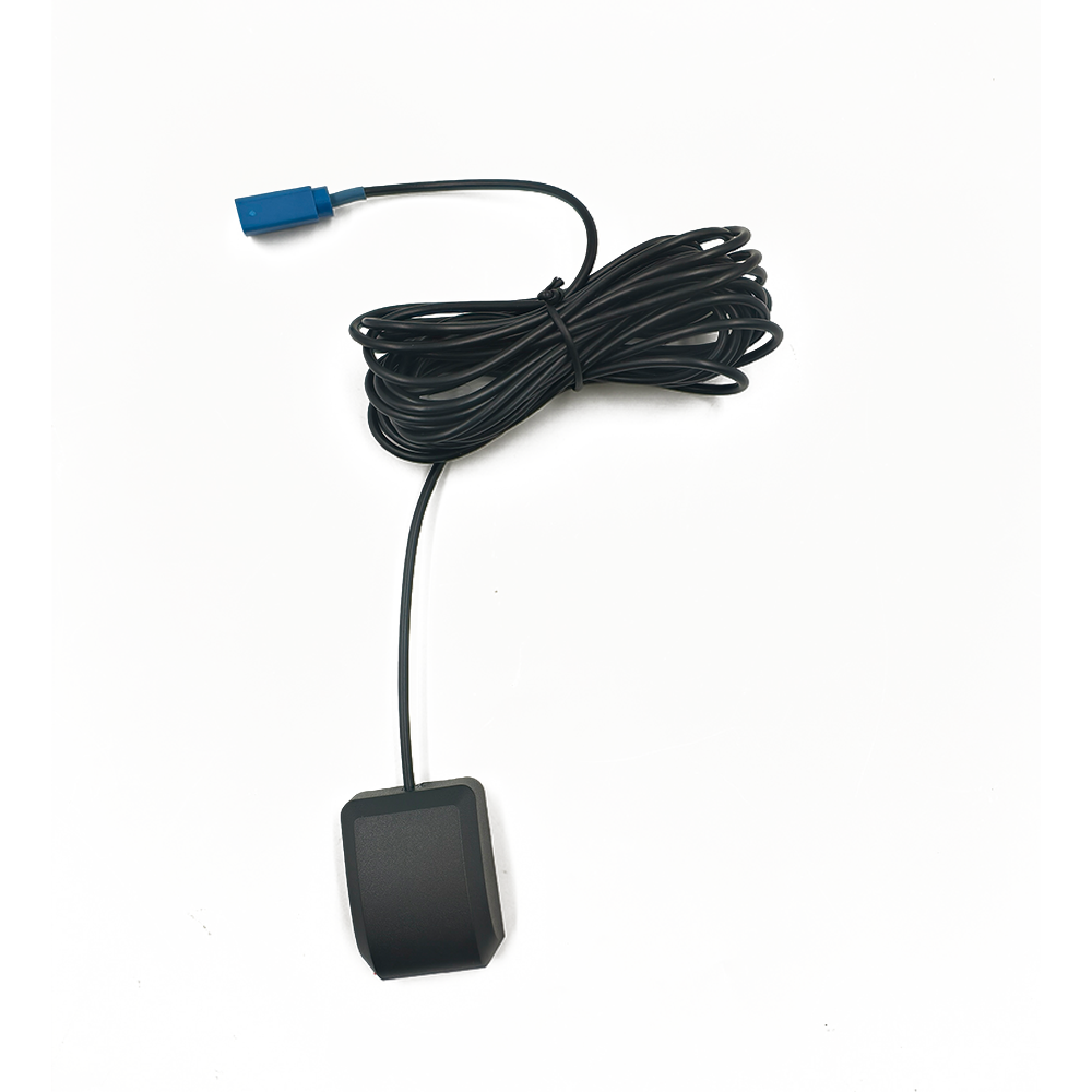
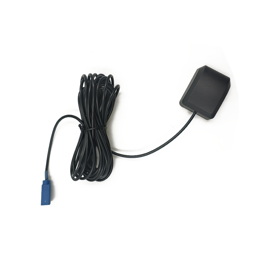
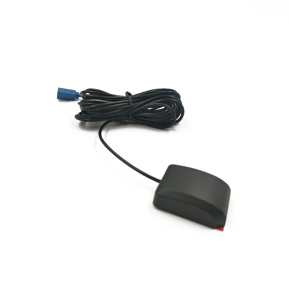
Overview
This overview establishes the critical role of these specialized antennas, differentiating them from their consumer-grade counterparts and outlining the unique challenges they are built to overcome. A fleet management antenna is not a commodity; it is a high-reliability component designed for mission-critical operation.
The core function of a GNSS antenna within an FMS is to act as the primary sensor for position, velocity, and time (PVT). It must continuously capture extremely weak microwave signals from multiple satellite constellations (GPS, GLONASS, Galileo, BeiDou) orbiting over 20,000 kilometers away. This data is then processed by a GNSS receiver (often integrated into a telematics unit) and transmitted via cellular or satellite networks to a central server. The integrity of every subsequent decision—from estimating time of arrival to triggering geofence alerts—is entirely dependent on the quality and reliability of the raw signal received by this antenna.
The operating environment for a fleet vehicle antenna is arguably one of the most challenging for any electronic component. It must perform flawlessly while enduring:
Extreme Temperature Swings: From scorching heat on a black asphalt parking lot in Arizona to sub-freezing temperatures in a Minnesota winter.
Moisture and Contaminants: Continuous exposure to rain, snow, ice, sleet, high humidity, and road spray containing water, salt, oil, and chemicals.
Physical Shock and Vibration: Constant vibration from the engine and road surface, and sharp impacts from potholes and uneven loading docks.
Electromagnetic Interference (EMI): Operating in close proximity to the vehicle's own noisy electrical system, including alternators, ignition systems, and two-way radios.
UV Radiation: Prolonged exposure to direct sunlight, which can degrade plastics and adhesives over time.
Intentional and Unintentional Abuse: Potential for contact with car wash brushes, low-hanging tree branches, and loading equipment.
A consumer-grade or standard commercial antenna would quickly fail under these conditions, leading to data loss, inaccurate reporting, and ultimately, a failure of the fleet management system itself. Therefore, the term "ruggedized" encompasses a holistic approach to design, focusing on environmental hardening, electrical robustness, and mechanical resilience.
Rugged GNSS antennas for fleet management are typically characterized by their external, roof-mount design. This placement is intentional, providing a clear, unobstructed view of the sky, which is paramount for receiving signals from satellites at low elevations near the horizon. This maximizes the number of satellites in view, which in turn improves accuracy through better geometry (lower Dilution of Precision - DOP) and enables more advanced techniques like multi-path rejection.
Furthermore, these antennas are rarely just passive elements. They are often active antennas, meaning they incorporate a built-in Low-Noise Amplifier (LNA). This amplifier boosts the incredibly weak satellite signals before they travel down the lossy coaxial cable to the receiver. This is crucial for maintaining a strong signal-to-noise ratio (SNR), especially when using long cable runs, which are common in large vehicles like trucks and buses.
In summary, the rugged GNSS antenna is the unsung hero of modern logistics. It is the critical data acquisition point, the "unsentinel" that silently and reliably gathers the essential location intelligence that powers the entire fleet management ecosystem. Its design philosophy is not one of minimal sufficiency but of maximal endurance, ensuring data continuity and system integrity in the face of relentless environmental and operational challenges.
Design and Construction
The construction of a rugged GNSS antenna is a masterclass in balancing high RF performance with extreme environmental durability. Every material choice, mechanical feature, and internal component is selected and engineered to meet the dual mandates of precision and resilience. This section deconstructs the anatomy of a typical high-quality fleet management antenna, exploring the layers of protection and performance built into its design.
The Radiating Element: Heart of the System
At the core of the antenna lies the radiating element, responsible for actually transmitting and receiving electromagnetic waves. For rugged GNSS applications, the most common design is a patched antenna, often based on a ceramic substrate.
Ceramic Patch: A precisely shaped metallic patch is fabricated on a high-dielectric ceramic substrate (e.g., aluminum oxide or titanate-based ceramics). This ceramic allows for a physically small radiator that is electrically resonant at GNSS frequencies (e.g., L1: 1575.42 MHz). The quality of the ceramic, specifically its dielectric constant (εr) and loss tangent (tan δ), is critical for efficiency and bandwidth.
Multi-Band Support: Modern fleet management requires tracking multiple GNSS bands (L1, L2, L5) for improved accuracy and redundancy. This is achieved through more complex patch designs, such as stacked patches (multiple layers of patches tuned to different frequencies) or slotted patches, which are engineered to operate over a wider bandwidth.
The Ground Plane: Stability and Shielding
Beneath the radiating patch lies a solid metal ground plane. This is not merely a mounting surface; it is an integral part of the antenna's performance. It defines the antenna's pattern, providing a stable reference for radiation and, crucially, acting as a shield against EMI from the vehicle below. A high-quality, large ground plane is essential for maintaining a consistent radiation pattern and high gain at low elevation angles, which is key to seeing satellites near the horizon.
The Low-Noise Amplifier (LNA): Boosting the Faint Whisper
The satellite signal is astonishingly weak by the time it reaches the antenna. To prevent it from being drowned out by noise in the transmission cable, a Low-Noise Amplifier (LNA) is integrated directly into the antenna housing. The design of this circuit is paramount:
Low Noise Figure (NF): The primary metric for an LNA is its noise figure, which should be as low as possible (typically < 2 dB). A lower NF means the amplifier adds minimal inherent noise, preserving the fragile signal-to-noise ratio.
Gain: Typical gain values range from 26 dB to 40 dB. This provides enough amplification to overcome cable losses but must be carefully chosen to avoid overdriving the receiver and causing distortion.
Filtering: High-quality LNAs include band-pass filters at their input. These filters are tuned to the GNSS bands and are essential for rejecting out-of-band interference from powerful nearby transmitters like cellular networks, FM radio, and two-way radios (e.g., CB, VHF). Without this filtering, these signals can desensitize or even damage the downstream receiver.
Robustness: The LNA components must be selected for automotive-grade temperature ranges (-40°C to +85°C or better) and be able to withstand voltage spikes and reverse polarity events common in vehicle electrical systems.
Environmental Protection: The Armored Shell
The internal components are encapsulated within a protective housing, the design of which is key to ruggedization.
Radome Material: The top cover, or radome, must be radio-frequency transparent. Materials like polycarbonate, ABS, or polyetherimide (ULTEM) are common. They are chosen for high impact strength, UV stability (to prevent yellowing and brittleness), and stable dielectric properties across the temperature range.
Housing Base: The base is typically made from a metal like die-cast zinc or stainless steel. This provides:
EMI Shielding: It acts as a Faraday cage, protecting the sensitive LNA from external RF interference.
Heat Sinking: It dissipates heat generated by the LNA.
Physical Strength: It provides a robust platform for the mounting hardware.
Sealing and Potting: Environmental sealing is achieved through multiple methods:
Gaskets and O-rings: A high-quality silicone rubber gasket between the radome and the base creates a water-tight seal.
Potting Compound: The entire internal cavity, including the PCB holding the LNA, is often filled with a rigid or flexible polyurethane or epoxy potting compound. This serves three critical functions: (1) it waterproofs the electronics, (2) it provides superb resistance to shock and vibration by immobilizing components, and (3) it offers thermal conductivity to help manage heat.
Mounting and Connectivity: Ensuring a Secure Link
Mounting Options: Antennas are designed for permanent installation using strong magnetic mounts (for temporary or metal roofs), direct drill-mounting with gaskets, or adhesive mounts for non-metal surfaces. All are engineered to withstand high wind forces at highway speeds.
Cable and Connector: The coaxial cable is typically low-loss RG-174 or LMR-195 with a heavy-duty, UV-resistant PVC or FEP jacket. The connector is almost always an SMA or TNC type, with weatherproofing features like a rubber boot or inherent sealing (as in TNC). Many designs feature fully molded cable assemblies where the cable is integrated into the housing, eliminating a potential failure point for water ingress.
In conclusion, the construction of a rugged GNSS antenna is a multi-disciplinary effort that merges RF engineering, materials science, and mechanical design. It transforms a delicate electronic sensor into a robust, automotive-grade product capable of surviving on the front lines of commerce, all while delivering the pristine signal quality required for accurate fleet management.
Working Principles
The operation of a rugged GNSS antenna is a process of selective acquisition, amplification, and preservation of incredibly faint signals amidst a hostile RF environment. Understanding its working principles goes beyond basic antenna theory and delves into the intricacies of signal conditioning and interference mitigation, which are critical for reliable fleet data.
Fundamental Reception: The Patch Antenna
The ceramic patch antenna operates as a resonant cavity. The metal patch, dielectric ceramic, and ground plane form a structure that resonates at specific GNSS frequencies. The primary mechanism of radiation is through fringing fields at the edges of the patch. The antenna is designed to be sensitive to Right-Hand Circularly Polarized (RHCP) waves, which is the polarization used by all GNSS satellites. This design inherently provides some rejection of Left-Hand Circularly Polarized (LHCP) signals, which are typically created by reflections (multipath) off the ground or buildings.
The Critical Role of the Ground Plane
The ground plane is not passive. It serves multiple simultaneous functions:
Pattern Definition: It creates the antenna's radiation pattern. A well-designed ground plane ensures a near-hemispherical pattern, providing strong gain from the horizon up to the zenith. This is vital for tracking satellites at low elevations.
Shielding: It acts as an electromagnetic shield, blocking noise and interference emanating from the vehicle's electronics located beneath the antenna. This is a first line of defense against engine noise, alternator whine, and other broadband interference.
Balun Function: It helps to suppress common-mode currents that can flow on the outside of the coaxial cable shield. These currents can distort the radiation pattern and act as a source of noise themselves.
Signal Amplification and Preservation: The LNA
The signal power from a GNSS satellite is approximately -130 dBm (decibels relative to one milliwatt). This is billions of times weaker than the signal from a cell phone. The LNA's job is to amplify this signal without adding significant noise.
Noise Figure (NF): This is the most important specification. If the LNA has a noise figure of 2 dB, it means the Signal-to-Noise Ratio (SNR) at its output is 2 dB worse than at its input. A low NF is non-negotiable for acquiring and tracking weak signals.
Gain: The amplifier provides gain, typically 26-40 dB, to boost the signal well above the noise floor of the subsequent stages (the cable and the receiver). The gain must be high enough to overcome cable loss (which can be several dB for long runs) but not so high that it saturates the receiver's front-end with amplified noise or strong out-of-band signals.
Filtering: The Spectral Bouncer
The urban and vehicular RF environment is incredibly crowded. A fleet vehicle might be driving past cell towers, broadcast radio antennas, and other two-way radios. The integrated band-pass filter is the antenna's "spectral bouncer." It is a passive circuit (using components like dielectric resonators or SAW filters) that is tuned to be a window only for GNSS frequencies (e.g., 1550-1610 MHz). It aggressively attenuates any signals outside this band. This is critical because:
Receiver Desensitization: Strong out-of-band signals can overload the receiver's front-end, making it "deaf" to the weak GNSS signals even if they are present.
Intermodulation: Strong signals can mix within non-linear components of the receiver, creating spurious signals that can fall directly within the GNSS band, acting as in-band interference.
Multipath Mitigation
A significant source of error in GNSS positioning is multipath, where the signal arrives at the antenna not directly, but after reflecting off surfaces like the ground or other vehicles. Rugged antennas combat this through:
RHCP Design: Reflections often reverse the polarization of a signal. Since the antenna is designed for RHCP, it is naturally less sensitive to these reflected LHCP signals.
Controlled Radiation Pattern: A well-designed ground plane and patch create a pattern with lower gain towards the horizon and below, where reflections are most likely to originate. Some advanced antennas use controlled reception pattern antenna (CRPA) techniques with multiple elements to electronically null out interfering and multipath signals, though this is more common in military/aviation than standard fleet systems.
Power Delivery (Bias-T)
Active antennas require power for the LNA. This is conveniently supplied by the GNSS receiver itself through the same coaxial cable that carries the RF signal. This is achieved via a Bias-T circuit. The receiver injects a DC voltage (typically 3V to 5V) onto the center conductor of the cable. Inside the antenna, an inductor (RF choke) blocks this DC from entering the RF path and directs it to the LNA's power supply circuitry. Simultaneously, a capacitor blocks the DC from going back towards the receiver while allowing the amplified RF signal to pass through. This elegant solution requires only a single cable for both power and data.
In essence, the working principle of a rugged GNSS antenna is one of transformation and protection. It transforms a faint, wide-spectrum RF environment into a clean, powerful, and narrowly defined GNSS signal. It doesn't just receive; it actively conditions the signal, fights interference, and provides the receiver with the best possible data to calculate an accurate and reliable position fix for the fleet management system.
Advantages and Challenges
-
The deployment of a purpose-built rugged GNSS antenna offers a compelling set of advantages that directly translate to operational benefits for a fleet management system. However, achieving this performance and durability introduces specific challenges and trade-offs that system integrators and fleet managers must understand.
Advantages
Superior Reliability and Uptime: This is the paramount advantage. The hardened construction ensures continuous operation through extreme weather, physical shock, and chemical exposure. The use of potting compounds immobilizes components against vibration, a primary cause of failure in standard electronics. This reliability directly translates to higher asset utilization and fewer "no data" events from the fleet.
Enhanced Signal Quality and Accuracy: The integrated, high-gain LNA and precise filtering provide the receiver with a strong, clean signal. This improves the receiver's ability to acquire satellites faster ( quicker Time to First Fix - TTFF) and maintain lock in challenging urban canyons and under tree cover. A cleaner signal also reduces pseudorange errors, leading to more accurate position reports.
Effective Interference Immunity: The combination of a solid ground plane (shielding from below), a metal housing, and sophisticated internal filtering makes these antennas highly resistant to EMI. This is critical for operation amidst the electrically noisy environment of a commercial vehicle, preventing dropouts and position drift caused by the vehicle's own systems or nearby transmitters.
Resistance to Multipath: The inherent properties of the patch antenna (RHCP, controlled pattern) provide a fundamental level of multipath rejection. This minimizes a key source of positioning error, leading to more consistent and truthful location data, which is vital for geofencing accuracy and route replay.
Long-Term Durability and Lower TCO: While the initial purchase price is higher than a non-rugged antenna, the total cost of ownership (TCO) is often lower. Their resistance to failure eliminates the costs associated with truck rolls, technician time, vehicle downtime, and replacement units. The UV-stable materials prevent degradation and cosmetic failure over many years of service.
Simplified Integration: Being a fully self-contained active antenna with a single coaxial output, it simplifies the design of the telematics unit. The RF design challenges (amplification, filtering) are handled at the antenna, allowing the receiver design to be more focused on digital processing.
Challenges and Considerations
Higher Unit Cost: The use of automotive-grade components, robust materials (metal housing, high-quality cable), potting, and rigorous testing inevitably results in a higher per-unit cost compared to consumer-grade antennas. This must be justified by the value of continuous, reliable data.
Size and Weight: Rugged antennas are typically larger, heavier, and more conspicuous than their consumer counterparts due to the metal housing, larger ground plane, and potting. This can sometimes make installation more complex and requires a robust mounting solution.
Power Dependency: As active antennas, they require a DC power source from the receiver. A fault in the receiver's bias-T circuit or a break in the coaxial cable can not only stop the signal but also deprive the antenna of power, making it completely inoperable, whereas a passive antenna would still function (though with degraded performance).
Complexity of Design and Manufacturing: Designing a high-performance antenna that also meets harsh environmental standards is a complex task requiring expertise in multiple engineering disciplines. The manufacturing process is also more involved, requiring steps like potting and precise sealing, which can impact production yield and cost.
Cable as a Potential Point of Failure: While the antenna itself is rugged, the coaxial cable running from it is vulnerable to damage, crushing, or connector corrosion if not installed properly with strain relief and weatherproofing. A fully molded design mitigates this but makes field repair impossible.
Performance Trade-offs in Miniaturization: There is constant pressure to make antennas smaller and lower profile. However, reducing the size of the ground plane can negatively impact the radiation pattern (reducing low-elevation gain) and shielding effectiveness. Engineering a small yet high-performance rugged antenna is a significant challenge.
In conclusion, the advantages of rugged GNSS antennas are overwhelmingly aligned with the core needs of commercial fleet management: unwavering reliability, data accuracy, and system integrity. The challenges are primarily economic and logistical. The decision to specify a rugged antenna is an investment in the quality and continuity of the fleet data stream, recognizing that the cost of antenna failure—in terms of lost visibility, inefficient operations, and missed alerts—far outweighs the initial premium paid for a hardened component.
Applications and Future Trends
-
The application of rugged GNSS antennas is central to the core functions of modern fleet management, and their role is expanding as technology evolves. Furthermore, new trends in connectivity, automation, and data analytics are shaping the future requirements for these critical components.
Core Applications in Fleet Management
Real-Time Asset Tracking and Visibility: The most fundamental application. Provides dispatchers and managers with a live view of vehicle location, enabling proactive customer service, estimated time of arrival (ETA) accuracy, and theft recovery.
Route Optimization and Geofencing: Accurate location data allows software to monitor route adherence, identify inefficient routes, and create virtual geographic boundaries (geofences). This triggers alerts for entry/exit, enabling automated job status updates, security alerts, and monitoring of authorized use.
Driver Behavior Monitoring (Telematics): By combining precise location with data from the vehicle's CAN bus, the system can monitor harsh braking, rapid acceleration, cornering, and speeding. This promotes safer driving, reduces fuel consumption, and lowers maintenance costs.
Hours of Service (HOS) Compliance: In regions like the US and EU, drivers must comply with strict driving and rest time regulations. GNSS data provides irrefutable proof of vehicle movement and stoppage, automatically logging driving time and ensuring legal compliance.
Temperature Monitoring and Cargo Security: For refrigerated trucks ("reefers"), the telematics unit monitors cargo temperature. GNSS location is stamped onto these temperature reports, creating an audit trail to prove the cold chain was maintained throughout the journey. It also provides location data in the event of unauthorized door opening.
Future Trends and Evolving Requirements
Demand for Higher Accuracy: The future of logistics involves hyper-efficient yard management, automated docking, and advanced driver-assistance systems (ADAS). This requires centimeter-level accuracy, moving beyond standard GNSS to Precise Point Positioning (PPP) and Real-Time Kinematic (RTK) techniques. This will drive the need for antennas with even more stable phase centers and support for multiple frequencies (L1, L2, L5).
Integration with Other Technologies (Sensor Fusion): The antenna will become part of a broader sensor suite. Future "smart antennas" may integrate inertial measurement units (IMUs) like accelerometers and gyroscopes. This allows for dead reckoning, providing continuous positioning in GNSS-denied environments like tunnels, urban canyons, and dense forests by fusing GNSS data with inertial data.
The Advent of Automotive V2X (Vehicle-to-Everything): As trucks begin to communicate with each other (V2V), infrastructure (V2I), and networks (V2N), the antenna roof pod may evolve into a multi-function hub. It could house not only GNSS but also DSRC (Dedicated Short-Range Communication) or C-V2X (Cellular V2X) antennas, creating a unified, ruggedized communication module.
Enhanced Interference Mitigation and Cybersecurity: As jamming and spoofing devices become more accessible, protecting the integrity of the GNSS signal becomes a security issue. Future rugged antennas may incorporate advanced anti-jamming capabilities, using multi-element designs to automatically nullify interference sources, ensuring operational continuity even under attack.
Predictive Maintenance and IoT Integration: The antenna itself could become a data source. Sensors could monitor its own health—internal temperature, moisture detection, vibration levels—and transmit this data proactively, enabling predictive maintenance before a failure occurs and ensuring the highest possible system uptime.
Standardization and Modularity: To simplify logistics and installation for large fleets, there may be a move towards more standardized form factors and connectors, or even modular designs where different sensing and communication modules can be snapped onto a common, powered roof-mounted base.
In summary, the application of the rugged GNSS antenna is moving from providing a simple location point to being the foundational sensor for a complex ecosystem of data-driven operational tools. Its future evolution is tied to the trends of automation, connectivity, and precision, requiring it to become more accurate, more integrated, smarter, and more secure to meet the demands of the next generation of intelligent fleet management.
Conclusion
In the intricate and high-stakes world of modern logistics, data is the new currency. The ability to know the precise location, status, and condition of every asset in a fleet in real-time is no longer a luxury but a fundamental requirement for competitiveness, efficiency, and security. This entire ecosystem of data-driven decision-making rests upon a single, critical point of failure: the GNSS antenna.
As this series has detailed, a standard antenna is utterly inadequate for this task. The commercial vehicle environment is an electronic battlefield, combining relentless physical punishment with a hostile electromagnetic spectrum. Only a purpose-built rugged GNSS antenna—engineered with a hardened shell, a shielded interior, a sensitive yet selective radiating element, and a robust low-noise amplifier—can hope to operate reliably in this arena. It is not merely a component; it is a high-reliability sensor, designed and built to military-grade standards for continuous commercial service.
The value proposition of this antenna is clear and compelling. Its advantages—unmatched reliability, superior signal integrity, inherent interference immunity, and long-term durability—directly translate into tangible business outcomes: reduced downtime, lower fuel costs, improved safety, regulatory compliance, enhanced customer satisfaction, and greater asset utilization. While its initial challenges of higher cost and size are real, they are overwhelmingly outweighed by the total cost of ownership and the strategic value of uninterrupted, high-quality data.
Looking forward, the role of the rugged antenna is only set to expand. As fleet management evolves towards greater automation, precision, and connectivity, the antenna will evolve in lockstep. It will become the platform for multi-frequency, multi-constellation GNSS reception, the fusion point for inertial and other environmental sensors, and the integrated hub for V2X communication. Its ability to resist jamming and spoofing will make it a critical node in cybersecurity for mobile assets.
In conclusion, specifying a high-quality rugged GNSS antenna is one of the most important decisions a fleet operator can make. It is an investment in the very foundation of their operational intelligence system. It is the unsung sentinel on the roof of every truck, bus, and trailer, silently ensuring that the stream of data that powers the global supply chain remains flowing, accurate, and utterly dependable, mile after grueling mile.


 Language
 En
En Cn
Cn Korean

 Home >


 18665803017 (Macro)


