

-
Products -PCBA Manufacturing RF Connectors RF Cable Assemblys Embedded Antennas External Antennas Positioning Chips and Modules
RF Connectors

RF Cable Assemblys
Embedded Antennas
External Antennas
Positioning Chips and Modules


 Language


Language


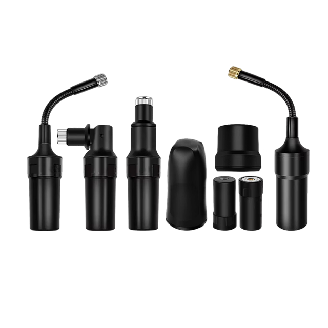

The Robust GNSS RTK Helical Antenna represents a specialized and high-performance class of antenna designed for the most demanding precision positioning applications. In the world of Real-Time Kinematic (RTK) GNSS, where centimeter-level accuracy is the benchmark, the antenna is not merely a passive receiver but the critical front-end component that dictates the quality, reliability, and robustness of the entire system. Unlike the more common patch antennas, the helical design offers a unique set of characteristics that make it exceptionally well-suited for challenging environments where signal strength, multipath rejection, and overall system integrity are paramount.
The term "Robust" in its name is a direct reference to its design philosophy. This antenna is engineered to perform consistently not just in ideal, open-sky conditions, but also in the face of adversity: under dense tree canopy, in urban canyons surrounded by skyscrapers, in mountainous terrain, and in the presence of strong electromagnetic interference. Its resilience makes it a preferred tool for professionals in surveying, construction, agriculture, and scientific research for whom mission failure due to poor satellite signal reception is not an option.
The core function of any GNSS RTK antenna is to act as the initial transducer, converting the incredibly faint electromagnetic waves transmitted from satellites orbiting over 20,000 kilometers away into a clean electrical signal for the receiver to process. However, for RTK, this task is elevated to an extreme level of precision. RTK relies on measuring the phase of the signal's carrier wave, which has a wavelength of just centimeters (e.g., ~19 cm for the GPS L1 frequency). Any imperfection in the antenna's ability to capture this phase faithfully—such as introducing phase noise or instability—translates directly into a positional error. The helical antenna's design is intrinsically advantageous for maintaining phase center stability, a holy grail of high-precision GNSS.
Furthermore, the "helical" design refers to its radiating element: a wire wound into a helix, typically above a ground plane. This structure is inherently resonant and is renowned for its characteristic circular polarization and symmetrical radiation pattern. For GNSS, which uses Right-Hand Circular Polarization (RHCP), this is a perfect match. The antenna's natural propensity to receive RHCP signals while rejecting their reversed, Left-Hand Circular Polarized (LHCP) counterparts (which are typically created by signal reflections) gives it a native and powerful defense against multipath error—one of the most significant sources of inaccuracy in GNSS positioning.
In summary, the Robust GNSS RTK Helical Antenna is a purpose-built instrument for excellence in precision. It is the cornerstone of a reliable RTK system, designed to ensure that the receiver is provided with the highest quality signal possible, even when operating at the very limits of GNSS technology. Its role is to maximize satellite signal availability, minimize measurement error at the source, and provide the consistent performance required to achieve and maintain integer ambiguity resolution—the key to centimeter accuracy—in real-time, across a wide range of demanding field conditions.
The design and construction of a Robust GNSS RTK Helical Antenna is a sophisticated interplay of electromagnetic theory, mechanical engineering, and materials science. Every aspect is meticulously optimized for performance, durability, and signal integrity. The architecture is distinctly different from the common flat patch antenna and can be broken down into its core components.
1. The Radiating Element: The Helix
The heart of the antenna is the helical element itself. It is typically constructed from a durable, high-conductivity material like copper, brass, or silver-plated wire, wound into a precise spiral or helix shape. The key design parameters are:
Diameter (D): The width of the helix.
Pitch (S): The distance between turns of the coil.
Number of Turns (N): The total turns in the helix.
Axial Length (L): The overall height of the helical section.
For GNSS applications, the antenna typically operates in axial mode. In this mode, the helix's circumference is approximately one wavelength at the target frequency (C = πD ≈ λ). The radiation pattern is directed along the axis of the helix, producing a directional, pencil-like beam. This is a significant contrast to the hemispherical pattern of a patch antenna. The axial mode provides higher gain towards the horizon, which is crucial for tracking low-elevation satellites, thereby increasing the number of available satellites and improving geometry (lower DOP values).
2. The Ground Plane
A critical component located directly beneath the helix is the ground plane. This is a circular or square metallic disc that serves several essential functions:
Directivity: It acts as a reflector, shaping the radiation pattern. Without it, the helix would have a bi-directional pattern. The ground plane reflects energy forward, creating a unidirectional pattern focused on the sky.
Shielding: It acts as an electromagnetic shield, blocking noise and interference originating from below the antenna (e.g., from the receiver itself, cables, or the ground). This is vital for maintaining a high signal-to-noise ratio (SNR).
Phase Center Stability: A well-designed, large ground plane contributes significantly to a stable electrical phase center, which is less susceptible to variation with satellite azimuth and elevation angle.
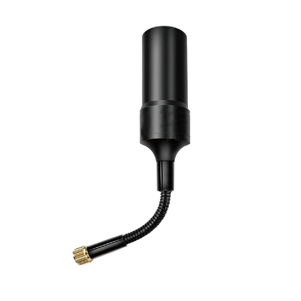
3. The Feed Network and Matching Circuit
The point where the coaxial cable connects to the helix is the feed point. Achieving maximum power transfer requires an impedance matching network to transform the native impedance of the helix (which can be around 100-150 Ω) to the standard 50 Ω impedance of the coaxial cable. This is often accomplished with a microstrip matching stub or a tapered section integrated into the feed point. A balun (balanced-to-unbalanced transformer) is also integrated here to prevent unwanted common-mode currents from flowing on the outside of the cable shield, which can act as a secondary antenna and introduce noise and phase errors.
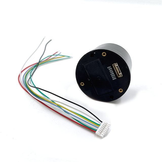
4. The Low-Noise Amplifier (LNA)
GNSS signals are exceptionally weak by the time they reach the Earth's surface. Therefore, a high-quality, low-noise amplifier is embedded within the antenna housing, very close to the feed point. Its purpose is to amplify the faint signals before any significant loss can occur in the transmission cable. The LNA must have:
High Gain: Typically 25-40 dB, to overcome downstream cable losses.
Very Low Noise Figure: Often less than 2 dB, meaning it adds almost negligible internal noise to the already weak signal.
Linear Operation: It must remain linear across a wide dynamic range to avoid distorting the signals, which would corrupt the precise phase measurements.
The LNA is usually powered via phantom power (DC voltage supplied up the center conductor of the coaxial cable from the receiver).
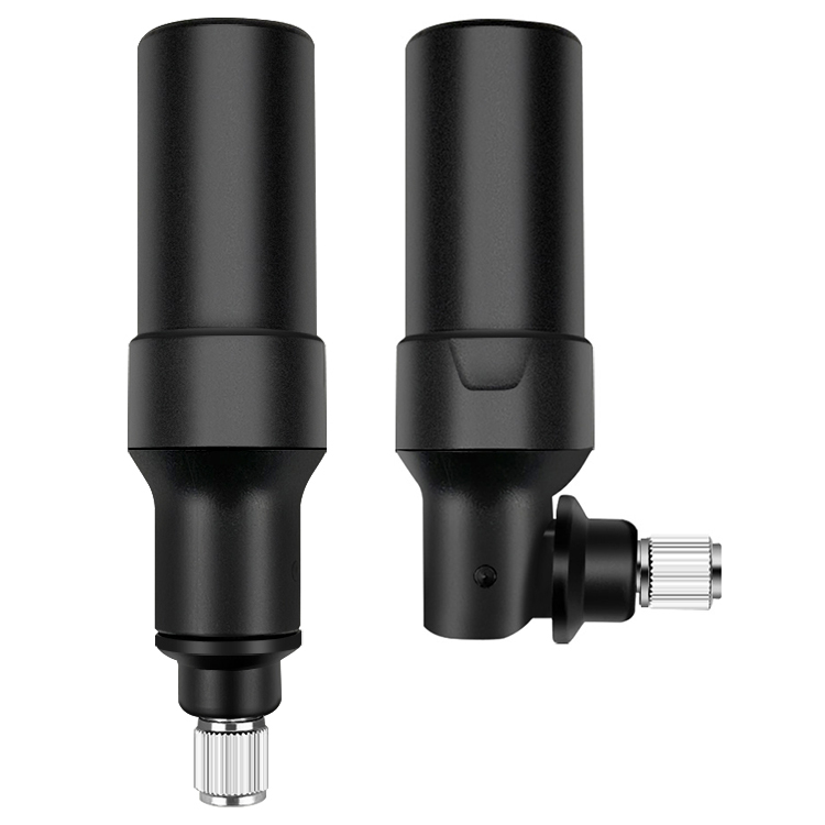
5. The Radome and Structural Housing
The "Robust" nature of the antenna is embodied in its external housing. The entire delicate assembly is protected by a radome—a cover made from a material that is transparent to GNSS radio frequencies. This is typically a low-loss plastic (like ABS or polycarbonate) or, in higher-end models, a premium material like ceramic. Ceramic radomes offer superior durability and exceptional RF transparency with minimal signal phase distortion. The housing is designed to be weatherproof (IP67 rated or higher), waterproof, and resistant to UV radiation, chemicals, and physical impact. It often features a built-in or optional choke ring base, which further enhances multipath rejection by creating a high-impedance barrier to signals arriving from low angles.
6. Integration of Multi-Band Operation
Modern RTK requires reception of multiple frequencies (L1, L2, L5, etc.). A quadrifilar helical antenna (QHA) with multiple intertwined helices is a common design to achieve this. Each helix can be tuned to a specific frequency, or a more complex single helix with a wider bandwidth can be used. The feed network becomes more complex to combine these signals correctly without mutual interference.
The construction is therefore a balance of electromagnetic precision and physical ruggedness, resulting in a unit that is both a highly sensitive scientific instrument and a tough field-worthy tool.
The working principle of the Robust GNSS RTK Helical Antenna is fundamentally based on its ability to efficiently capture right-hand circularly polarized (RHCP) electromagnetic waves and convert them into a stable, amplified electrical signal with minimal distortion of the carrier phase information.
1. Circular Polarization and Axial Mode Radiation:
The helical antenna is a natural emitter and receiver of circularly polarized waves. As the RF current travels along the helical wire, its radiation adds up in space with a constant phase rotation, resulting in a wave that rotates as it propagates. A right-wound helix produces RHCP waves, which perfectly matches the polarization of all modern GNSS signals. This is a first-line defense against multipath. When an RHCP signal reflects off a surface, its polarization often reverses to become primarily Left-Hand Circular Polarized (LHCP). The helical antenna is inherently less sensitive to LHCP signals, thus naturally rejecting a large portion of reflected interference.
When operating in axial mode, the antenna exhibits a directional radiation pattern along its central axis. This provides two key benefits for RTK:
Higher Gain at Low Elevations: The pattern offers more uniform gain across the sky, including towards the horizon. This allows it to better acquire and track satellites at lower elevations, increasing the number of useable satellites and improving the overall satellite geometry (dilution of precision - DOP). This is crucial for maintaining a fixed RTK solution in obstructed environments.
Front-to-Back Ratio: The directional pattern means it is very sensitive to signals from above and significantly less sensitive to signals from below. This further suppresses multipath reflections from the ground or the platform on which it is mounted.
2. Phase Center Stability:
The most critical principle for an RTK antenna is its Phase Center behavior. The phase center is the hypothetical point from which the transmitted or received electromagnetic radiation appears to originate. For precision phase measurements, this point must be stable and consistent for all frequencies and all directions of arrival (azimuth and elevation). Any movement of the effective phase center translates directly into a measurable range error.
The helical antenna, particularly when coupled with a large, well-defined ground plane, exhibits excellent phase center stability. Its symmetrical structure means that the phase center variation (the small movement of this point) is minimal and, most importantly, highly predictable. Manufacturers perform precise anechoic chamber calibrations to map these variations and generate a Phase Center Variation (PCV) model. The RTK receiver/processor then applies this model to correct the measurements, eliminating this source of systematic error. The robustness of the helical design makes this PCV model more stable and reliable under real-world conditions compared to some other antenna types.
3. Signal Amplification and Integrity Preservation:
The weak currents induced in the helix by the satellite signals are immediately amplified by the integrated Low-Noise Amplifier (LNA). The proximity of the LNA to the radiating element is crucial. By amplifying the signal before it enters the lossy coaxial cable, the antenna ensures a high Signal-to-Noise Ratio (SNR) is delivered to the receiver. A high SNR is essential for the receiver's tracking loops to maintain lock on the signals and to reduce measurement noise, which directly impacts the time to achieve and the reliability of integer ambiguity resolution in RTK.
4. Multipath Mitigation:
The antenna combats multipath through a multi-layered approach:
Polarization Discrimination: Rejecting LHCP reflected signals.
Directional Pattern: Attenuating signals from below the horizon.
Choke Ring Effect: If present, the choke ring creates a corrugated surface that presents a high impedance to surface waves and low-angle reflections, effectively "choking" them off before they can interfere with the direct signals.
In essence, the helical antenna works by being an electromagnetically "quiet" and stable point of reference. It selectively listens to direct, RHCP signals from the sky, amplifies them cleanly, and delivers a pristine data stream to the receiver, providing the best possible raw material for the complex RTK algorithms to compute a centimeter-accurate position.
The Robust GNSS RTK Helical Antenna offers a compelling set of advantages that make it the preferred choice for high-stakes precision applications, but these come with certain trade-offs and challenges that must be considered.
Advantages:
Superior Multipath Rejection: This is its foremost advantage. The combination of inherent RHCP reception, high front-to-back ratio, and often an integrated choke ring gives it unparalleled ability to suppress reflected signals, leading to more reliable and accurate fixes in urban and natural canyon environments.
Excellent Low-Elevation Performance: The axial-mode radiation pattern provides higher gain towards the horizon compared to a patch antenna. This allows it to track satellites at lower elevations, increasing the number of visible satellites and improving satellite geometry (lower DOP). This is critical for availability in obstructed environments.
Wide Bandwidth: Helical antennas naturally have a wider bandwidth than patch antennas. This makes them inherently better suited for receiving multiple GNSS frequency bands (L1, L2, L5, etc.) with a single radiating element, simplifying the design for multi-constellation, multi-frequency operation.
High Phase Center Stability: The symmetrical physical structure and the use of a large ground plane contribute to a very stable and well-defined phase center. This minimizes systematic errors and makes the phase center variations (PCV) easier to model and correct for, which is fundamental for geodetic-grade accuracy.
Robustness and Durability: The design often lends itself to a more rugged mechanical construction. The internal elements are typically more robust than the fragile etched patterns of a patch antenna. Coupled with a tough ceramic or heavy-duty plastic radome, these antennas are built to withstand harsh field conditions, including physical impact, moisture, and extreme temperatures.
Challenges:
Size and Weight: The three-dimensional helical structure, combined with the necessary large ground plane and radome, typically results in an antenna that is larger, taller, and heavier than an equivalent-performance patch antenna. This can be a drawback for applications where size and weight are critical constraints, such as on small drones or for a surveyor carrying it on a backpack-mounted rover.
Cost: The manufacturing process for a precision helical antenna is often more complex and labor-intensive than for mass-produced patch antennas. The use of high-quality materials like ceramic radomes further drives up the cost. They are typically a premium-priced item.
Directionality: While its directional pattern is an advantage for performance, it can be a operational challenge. The antenna must be oriented with its axis vertical (pointing towards the zenith) for optimal performance. A significant tilt can introduce errors and reduce performance. This requires careful setup and a stable mounting platform, which is not always as critical for the more forgiving hemispherical pattern of a patch antenna.
Complexity of Integration: Designing a multi-frequency helical antenna (e.g., a quadrifilar helix) involves a more complex feed network and impedance matching system than a stacked-patch design. This can introduce additional design challenges and potential points of failure if not executed perfectly.
Wind Loading: The larger physical profile can make the antenna more susceptible to wind forces, which could be a concern for precise monitoring applications on a tripod or permanent installation in windy locations. A patch antenna's low profile is advantageous here.
In conclusion, the advantages of the helical antenna are predominantly related to superior performance in challenging RF environments, making it the tool of choice for critical applications where data integrity is non-negotiable. The challenges are primarily related to physical form factor, cost, and setup care, which may make a high-quality patch antenna a more suitable choice for applications where these factors are more important than ultimate performance.
The unique advantages of the Robust GNSS RTK Helical Antenna dictate its application in fields where resilience, reliability, and the highest levels of accuracy are required, often in less-than-ideal signal environments.
Applications:
Geodetic and Scientific Monitoring: This is the classic application for such high-performance antennas. They are deployed on permanent or semi-permanent monuments for crustal deformation studies (tectonic plate motion, volcanic uplift), subsidence monitoring (from aquifers or mining), and long-term reference stations for national geodetic networks. Their exceptional phase stability is critical for detecting millimeter-level movements over years.
Critical Infrastructure and Construction: For large-scale engineering projects like the construction of bridges, dams, tunnels, and high-rise buildings, the integrity of the control network is paramount. Helical antennas are used to establish robust base stations that must provide a reliable RTK correction stream to all rovers on site, even in the cluttered RF environment of a construction site with cranes and machinery.
Urban Surveying and Mapping: In dense urban environments, multipath from buildings and vehicles is the primary enemy of GNSS accuracy. Surveyors mapping utilities, conducting cadastral surveys, or performing asset management in cities rely on the superior multipath rejection of helical antennas to maintain fixed solutions and ensure data quality.
Precision Agriculture in Obstructed Terrain: While open fields are well-served by many antennas, farms with wooded areas, rolling hills, or numerous buildings benefit from the helical antenna's ability to track low-elevation satellites and resist multipath, ensuring continuous guidance for automated tractors and accurate data for yield mapping.
Marine and Hydrographic Surveying: On a vessel, the GNSS antenna is constantly moving and is surrounded by a perfect multipath generator: the flat, reflective surface of the water. Helical antennas, often with large choke rings, are used to provide the precise positioning needed for bathymetric surveys, dredging, and port construction.
Unmanned Aerial Vehicles (UAVs) for Corridor Mapping: For drone-based surveying of linear infrastructure like power lines, pipelines, and railways—which often involves flying under tree canopy or near structures—the high performance and light weight (of smaller helicials) can be a significant advantage for maintaining PPK/RTK positioning integrity.
Future Trends:
Tighter Integration with Inertial Navigation Systems (INS): The future of robust positioning lies in sensor fusion. We will see more tightly coupled systems where the GNSS antenna is physically and electronically integrated with a tactical-grade IMU. This creates a single, optimized navigation unit that provides continuous, precise positioning and orientation even during complete GNSS outages, which is vital for autonomous systems.
AI-Enhanced Adaptive Filtering: Future antennas may incorporate on-board processing or work in concert with the receiver to use artificial intelligence to identify and nullify multipath and interference in real-time. The antenna's radiation pattern could even be made electronically adjustable to "steer" nulls towards persistent sources of interference.
Further Miniaturization: Advances in materials and manufacturing, such as 3D printing of conductive elements and substrates, will allow the benefits of the helical design to be packaged into smaller and lighter form factors, making them more viable for size-constrained applications like wearable devices and small drones.
Integration of LEO Satellite Signals: As Low Earth Orbit satellite constellations (e.g., Starlink, Iridium) begin offering navigation services, future helical antennas may be designed to also receive these signals. Their wide bandwidth and design flexibility make them good candidates for this fusion of GNSS and LEO signals, which promises unprecedented robustness and accuracy.
Enhanced Cybersecurity and Spoofing Mitigation: For safety-critical applications, future antennas will incorporate hardware-level features to detect and mitigate GNSS spoofing attacks. This could involve using the antenna's pattern to direction-find a spoofing source or using polarization characteristics to distinguish authentic from fake signals.
Standardization of Multi-Constellation, Multi-Frequency Support: The trend will continue towards antennas that are optimally tuned for all current and future signals from GPS, Galileo, BeiDou, and GLONASS, becoming a true global standard without performance trade-offs.
The helical antenna will continue to evolve from a standalone precision sensor into an intelligent node within a larger, resilient, and multi-source positioning network.
Conclusion
The Robust GNSS RTK Helical Antenna stands as a pinnacle of precision RF design, purpose-built to overcome the most significant challenges inherent in high-accuracy satellite positioning. It is not a general-purpose component but a specialized tool engineered for environments where data integrity, reliability, and ultimate performance are non-negotiable. Its value proposition is clear: by providing superior multipath rejection, excellent low-elevation satellite tracking, and exceptional phase center stability, it delivers the highest quality raw signal data to the GNSS receiver.
This capability forms the indispensable foundation upon which reliable Real-Time Kinematic (RTK) positioning is built. The most advanced receiver algorithms are ultimately limited by the quality of the input they receive. The helical antenna ensures that this input is as clean, stable, and robust as possible, maximizing the chances of achieving and maintaining integer ambiguity resolution—the key to centimeter-level accuracy—in real-world conditions fraught with reflections and obstructions.
While its larger size, weight, and cost present certain trade-offs compared to patch antenna solutions, these are acceptable compromises for the professional and scientific user communities it serves. In applications ranging from monitoring the slow drift of tectonic plates to guiding autonomous machinery on a chaotic construction site, the helical antenna provides a trusted source of truth.
Looking forward, its role is not diminishing but evolving. As GNSS technology advances with new signals and constellations, and as it fuses with other technologies like inertial navigation and LEO satellite communication, the fundamental principles of the helical design—its inherent resilience and precision—will remain highly relevant. It will continue to be the cornerstone of robust positioning systems, adapting to become an even more intelligent and integrated component in the next generation of autonomous and safety-critical applications. In the relentless pursuit of accuracy, the Robust GNSS RTK Helical Antenna remains an essential and powerful instrument.

 86 0755 2819 9597
Lucy Yang | lucy.y@toxutech.com
Nicole Li | nicole@toxutech.com
Dotty Zhao | sales04@toxutech.com
Global Business Director / Sales Team / Global Operations


 En
En Cn
Cn Korean
 Home >


