

-
Products -PCBA Manufacturing RF Connectors RF Cable Assemblys Embedded Antennas External Antennas Positioning Chips and Modules
RF Connectors

RF Cable Assemblys
Embedded Antennas
External Antennas
Positioning Chips and Modules


 Language


Language


In the realm of geomatics and civil engineering, the quest for precision is eternal. The ability to determine a position on the Earth's surface with centimeter, or even millimeter, accuracy has transformed industries, from construction and agriculture to scientific research and land administration. At the heart of this transformation lies Real-Time Kinematic (RTK) technology, a powerful method of processing Global Navigation Satellite System (GNSS) signals. However, the extraordinary capabilities of RTK are fundamentally constrained by one critical component: the antenna. An RTK Precision Surveying GNSS Antenna is not a mere accessory; it is a high-precision scientific instrument designed to be the ultimate gatekeeper of signal integrity, enabling the mathematical magic of RTK to unfold.
To understand its paramount importance, one must first grasp the basic principle of RTK. Standard GNSS positioning, as used in smartphones or car navigators, relies on the code information modulated onto the satellite signal. This method is relatively robust but inherently limited, typically providing accuracy in the range of 1 to 5 meters. RTK, by contrast, uses the carrier phase of the signal itself. The carrier wave has a much shorter wavelength (e.g., approximately 19 centimeters for the GPS L1 frequency) compared to the code chips. By resolving the integer number of carrier waves between the satellite and the receiver—a process known as "integer ambiguity resolution"—RTK can measure the distance with millimeter-level precision. This allows it to achieve real-time positioning accuracy of 1 centimeter + 1 part per million (ppm) of the baseline distance, meaning an error of just over 1 cm for a 10 km baseline.
This process of resolving the integer ambiguity is exceptionally sensitive. It requires near-perfect measurement of the phase of the incoming satellite signal. Any corruption, delay, or perturbation of this phase measurement will prevent resolution or cause an incorrect resolution, leading to a "float" solution with drastically reduced (decimeter-level) accuracy. The antenna is the first element in the signal chain, and its role is to capture this phase information with absolute fidelity. The challenges it must overcome are immense:
Multipath: The phenomenon where a signal arrives at the antenna via two or more paths: the direct line-of-sight path and one or more paths reflected from the ground, buildings, or other objects. The reflected signal is delayed, distorting the phase measurement.
Phase Center Stability: The antenna's "phase center" is the theoretical point from which it appears to be radiating. In a perfect antenna, this point would be fixed and identical for all frequencies and all directions. In reality, it moves. Any movement of the phase center with the satellite's position in the sky introduces a measurable error indistinguishable from a real change in position.
Weak Signals: Satellite signals are incredibly weak by the time they travel over 20,000 kilometers to the Earth's surface, making them susceptible to noise and interference.
Multi-Constellation, Multi-Frequency Operation: Modern surveying requires tracking all available satellites from all constellations (GPS, GLONASS, Galileo, BeiDou) and on multiple frequencies (L1, L2, L5, etc.) to ensure reliability, speed, and accuracy in challenging environments.
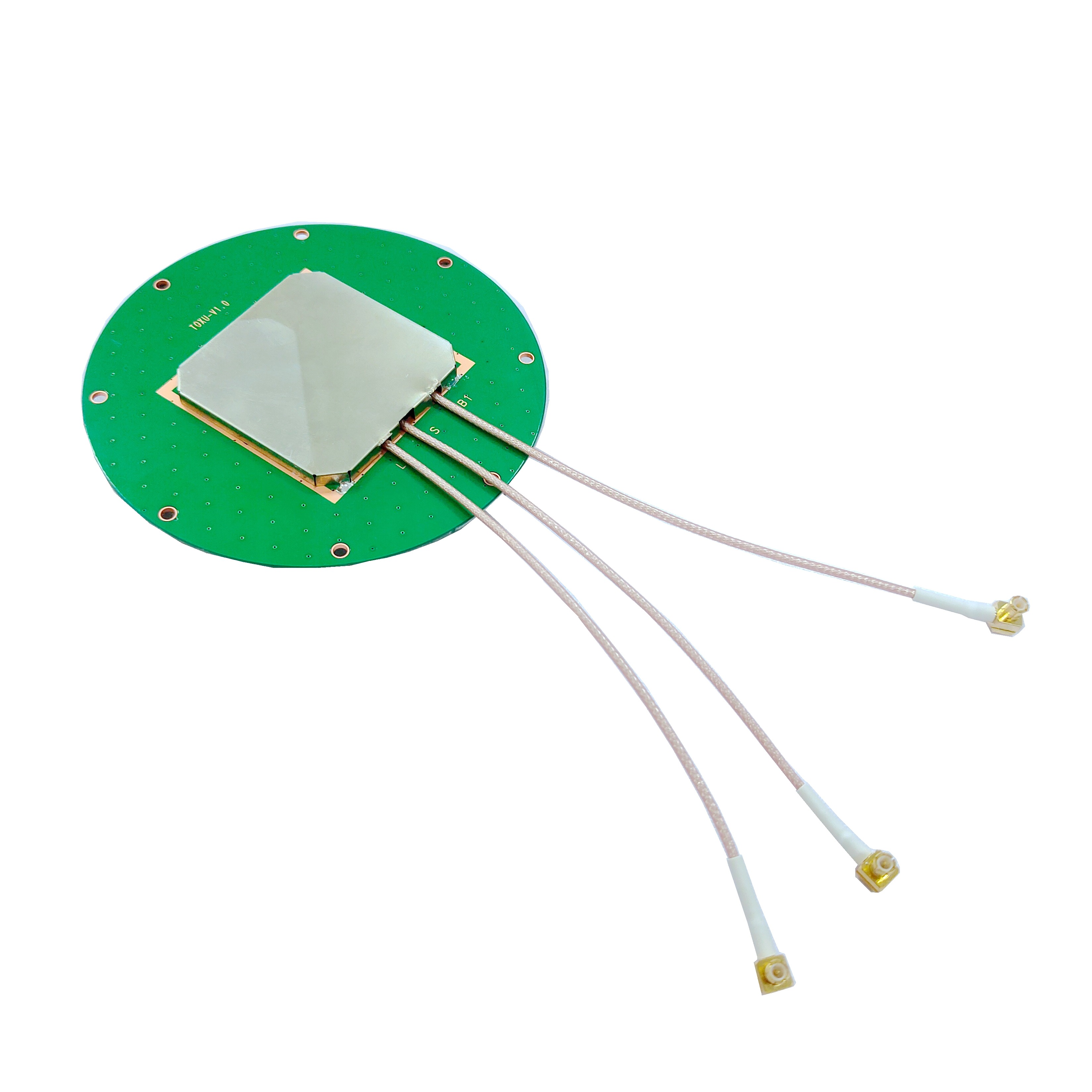
The RTK surveying antenna is meticulously engineered to address these challenges. It is typically a choke ring or precision pinwheel antenna built on a stable substrate, housed in a ruggedized outdoor package. It features a precisely defined ground plane, sophisticated elements to suppress multipath, and an integrated Low-Noise Amplifier (LNA) to boost weak signals without adding significant noise. Furthermore, its phase center variation (PCV) is meticulously calibrated across all angles and frequencies in an anechoic chamber, and these corrections are applied in the processing software to achieve the highest possible accuracy.
In essence, while the RTK receiver contains the complex algorithms, the antenna provides the pristine raw data upon which those algorithms depend. A surveyor using a top-tier receiver with a low-quality antenna will never achieve the same results as one using a mid-tier receiver with a geodetic-grade antenna. The antenna is the foundation. It is the critical interface between the chaotic real-world environment and the precise digital realm of the survey, transforming faint electromagnetic waves from space into a stable, trustworthy, and centimeter-accurate position on the ground.
The design and construction of an RTK Precision Surveying GNSS antenna is a meticulous exercise in electromagnetic engineering, materials science, and precision manufacturing. Every single aspect of its architecture is optimized for one goal: to provide an exceptionally stable and accurate phase measurement. Unlike consumer-grade antennas, where cost and size are primary drivers, surveying antennas prioritize performance above all else, resulting in a robust and complex layered structure.
1. The Radiating Element: The Heart of the Antenna
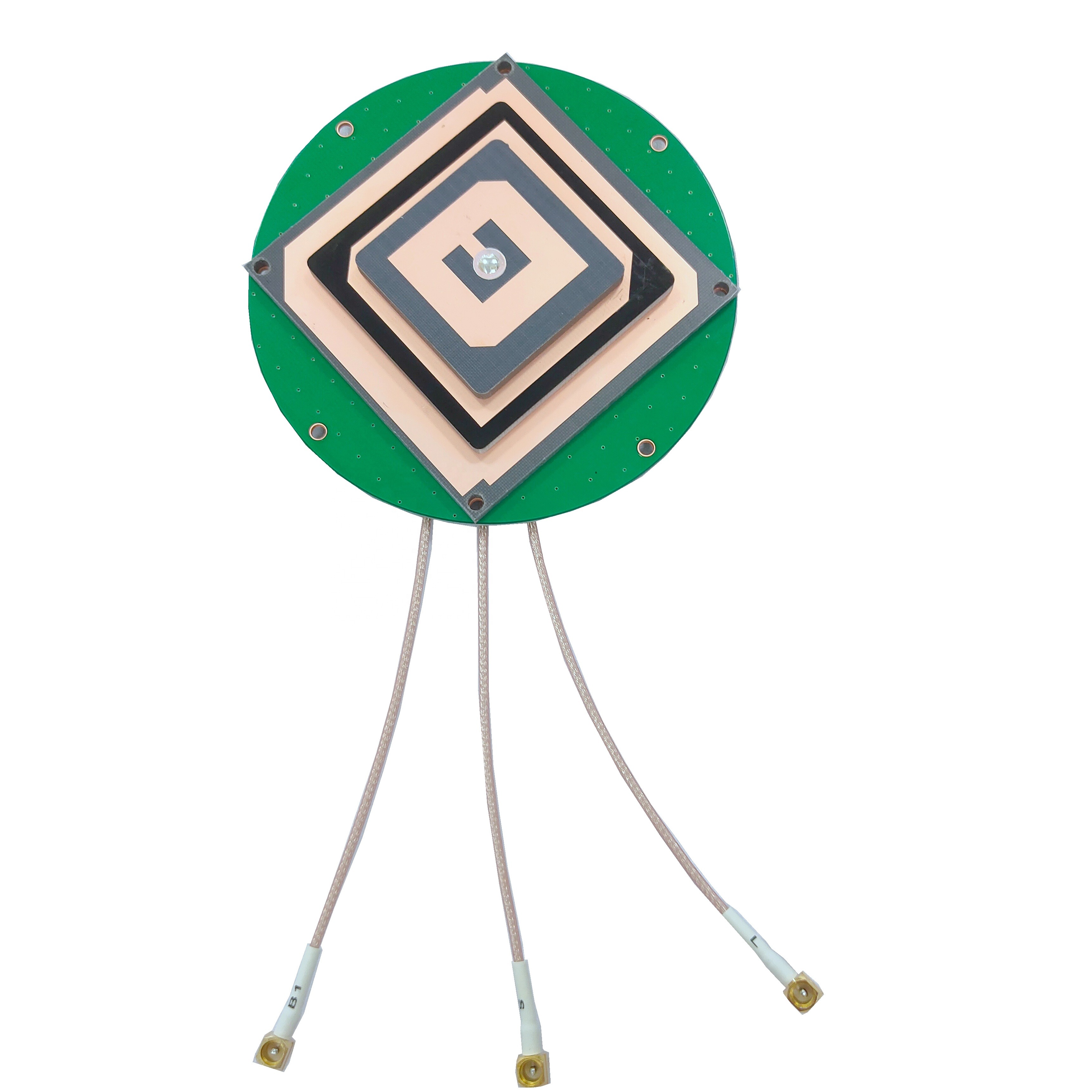
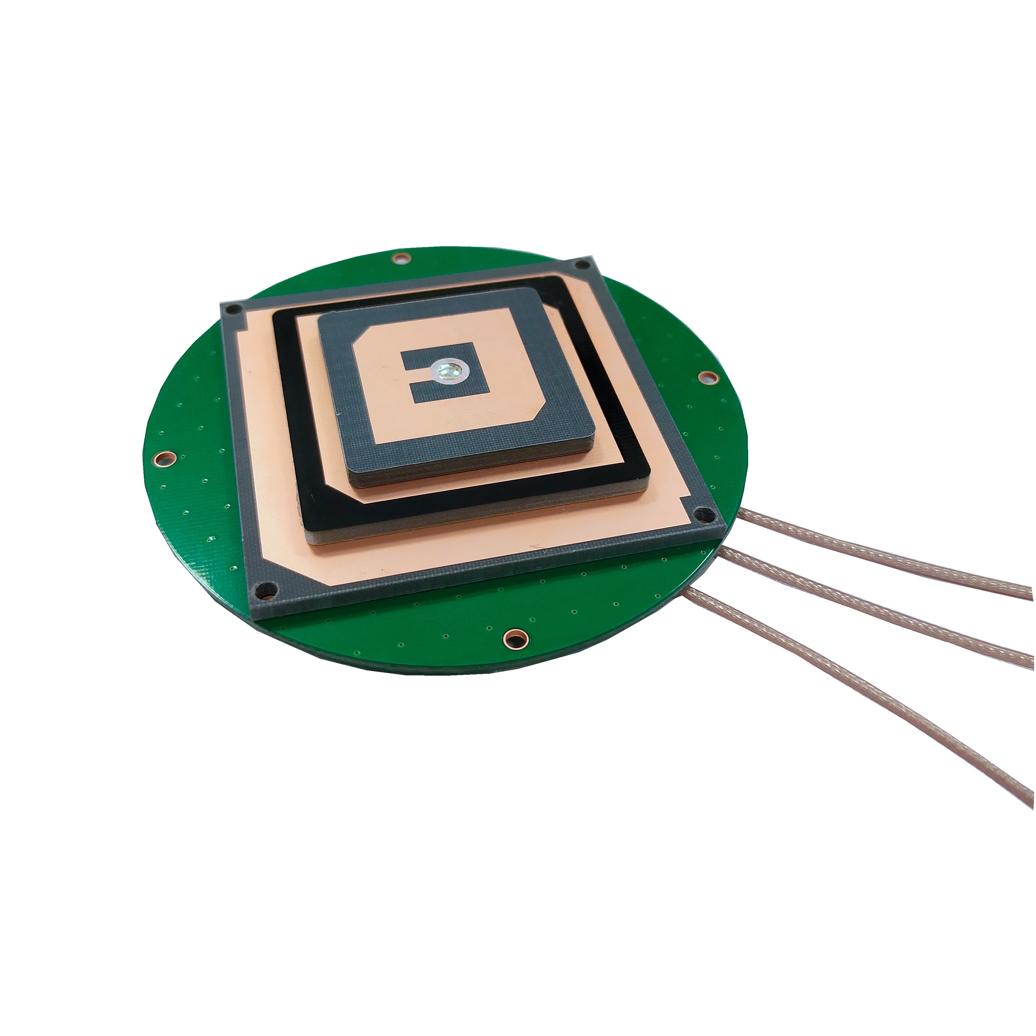
The core of the antenna is the radiating element, responsible for converting electromagnetic energy from the air into electrical current. For surveying-grade antennas, the most common type is a stacked patch design.
Patch Antenna Basics: A patch antenna consists of a flat, rectangular or circular sheet of conductor (the "patch") mounted over a larger ground plane, separated by a dielectric substrate.
Stacked Patches for Multi-Band Operation: To receive multiple frequency bands (e.g., GPS L1 and L2), survey antennas use multiple patches stacked on top of each other. The lower, smaller patch is tuned to the higher frequency (L1), while the upper, larger patch acts as a parasitic element resonant at the lower frequency (L2). This allows for independent optimization of performance across each band without compromising the antenna's physical size or phase center stability.
2. The Dielectric Substrate: A Foundation of Stability
The material between the patch and the ground plane is critical. Surveying antennas use high-quality, low-loss dielectric substrates with a stable dielectric constant. Common materials include:
Ceramics: Offer a high dielectric constant, allowing for a smaller antenna size, but can be more expensive and have a narrower bandwidth.
PTFE-based substrates (e.g., Rogers laminates): Provide an excellent balance of stable electrical properties, low loss tangent, and wide bandwidth, making them a popular choice for high-performance designs.
The substrate must be mechanically rigid and thermally stable. Its properties must not change with temperature or humidity, as this would shift the antenna's resonant frequency and, crucially, the location of its phase center.
3. The Ground Plane and Multipath Suppression
The ground plane is arguably as important as the radiating element itself. It serves two vital functions:
Directional Pattern: It creates the antenna's directional radiation pattern, ensuring maximum gain is directed towards the sky (where the satellites are) and minimal gain towards the horizon and below.
Multipath Rejection: This is its most crucial role. Reflected signals typically arrive at low elevation angles. A well-designed ground plane attenuates these signals. Survey antennas take this to the extreme with advanced ground plane designs:
Choke Rings: The gold standard for multipath suppression. A choke ring assembly consists of concentric, circular troughs (rings) of specific depths attached to the ground plane. These rings form a high-impedance surface that effectively "chokes" off surface currents induced by low-angle multipath signals. They create an exceptionally clean radiation pattern but result in a large, heavy, and expensive antenna.
Pinwheel or Radial Ground Planes: A more compact alternative. They use a series of grounded pins or metallic strips arranged radially around the antenna's core. These elements disrupt the surface waves that carry multipath energy, offering very good performance in a more portable form factor, common on rover poles.
4. Achieving Circular Polarization (RHCP)
GNSS signals are transmitted with Right-Hand Circular Polarization (RHCP). To receive them efficiently, the antenna must also be RHCP. A simple patch is linearly polarized. To achieve circular polarization, the antenna is fed at two points with signals that are 90 degrees out of phase (a quadrature phase shift). This can be done with:
A Single Feed with a Perturbation: A physical notch or tab unbalances the patch, creating two orthogonal modes with a 90-degree phase shift. This is simpler but less precise.
A Dual Feed with a Hybrid Coupler: A more sophisticated and precise method. Two separate feed points are driven through a 90-degree hybrid coupler circuit, which ensures perfect phase and amplitude balance. This results in a very pure circular polarization and a low Axial Ratio, which is critical for minimizing phase noise.
5. The Integrated Low-Noise Amplifier (LNA)
The antenna is almost always "active," meaning it contains an integrated LNA. The LNA's purpose is to amplify the extremely weak satellite signals (often below -130 dBm) immediately, before they travel down the cable to the receiver where they would be attenuated and degraded by cable loss. Key LNA characteristics for surveying are:
Very Low Noise Figure (< 2 dB, often < 1 dB): It must add almost no noise of its own.
High Gain (25-40 dB): To overcome downstream cable loss.
Excellent Linearity: To avoid being desensitized by strong out-of-band signals from cellular or radio transmitters.
6. Housing, Calibration, and Integration
The entire assembly is housed in a rugged, weatherproof (typically IP67-rated) casing. The radome—the top cover—is made from a material that is radio-transparent at GNSS frequencies (e.g., polycarbonate or ABS plastic) and is designed to have minimal impact on the antenna's performance.
Finally, each antenna design undergoes rigorous calibration in an anechoic chamber. Its precise Phase Center Variation (PCV) is measured for all frequencies and all angles of arrival (azimuth and elevation). This PCV data is stored in a file (often in ANTEX format) that can be loaded into the survey controller software. The software then applies these corrections to the raw measurements, mathematically moving the effective phase center to a single, stable virtual point, thereby eliminating this source of error and pushing accuracy to the millimeter level. This meticulous design and calibration process is what separates a precision surveying antenna from all others.
The working principle of an RTK surveying antenna is a symphony of physics and engineering, orchestrated to perform one task with impeccable accuracy: to act as a stable and faithful transducer of the carrier phase of GNSS signals. Its operation is not about simple signal reception but about the preservation of phase information with minimal corruption.
Fundamental Resonance and Radiation
At its core, the patch antenna operates as a resonant cavity. The metal patch and the ground plane form the two walls of this cavity, which is filled with the dielectric substrate. When excited by a radio frequency signal at its feed point(s), electromagnetic fields oscillate within this cavity. The dimensions of the patch are carefully designed to be half a wavelength long (within the dielectric material) at the target frequency. The oscillating fields "fringe" out beyond the edges of the patch, and it is these fringing fields that radiate energy into space (for transmission) or capture energy from space (for reception).
The Creation of a Directional Pattern
A key to the antenna's performance is its radiation pattern. A simple dipole antenna radiates equally in all directions. A surveying antenna must be highly directional. The ground plane beneath the patch acts as a reflector. Energy that would normally radiate downwards is reflected upwards, combining constructively with energy radiating upwards. This results in a hemispherical radiation pattern with maximum gain directed towards the zenith (straight up). The gain gradually decreases towards the horizon and is designed to fall off sharply below the horizon. This pattern is perfectly suited for satellite signals, which always arrive from above.
The Mechanism of Multipath Suppression
Multipath is a primary enemy of precision. A reflected signal takes a longer path than the direct signal, arriving at the antenna with a delay. This delay corrupts the precise phase measurement. The surveying antenna fights multipath through its radiation pattern and specialized ground plane.
Choke Rings: The choke rings are not simply metal rings; they are precisely calculated radial waveguide chokes. For signals arriving at low angles (the source of ground reflections), the rings present a very high impedance. This high impedance prevents currents from flowing on the outer surface of the ground plane, which are what would re-radiate and allow the antenna to receive these unwanted signals. Effectively, the choke rings make the ground plane appear electromagnetically much larger than it is physically, creating a very deep "null" in the antenna's sensitivity at low and negative elevation angles.
Pattern Nulling: Whether with choke rings or a pinwheel design, the result is a radiation pattern that is highly attenuated at angles below 5-10 degrees. Since most multipath signals arrive from these low angles, they are naturally rejected by the antenna's very design before they can even enter the signal chain.
The Critical Concept of the Phase Center
For standard positioning, the antenna's amplitude pattern (gain) is most important. For carrier-phase positioning, the phase pattern is everything. The Phase Center is the conceptual point in space from which the radiation appears to originate. For an ideal antenna, this would be a single, fixed point. In reality, it is a region, and its apparent location shifts depending on the frequency of the signal and the direction (elevation and azimuth) from which the signal arrives.
This movement, called Phase Center Variation (PCV), is a direct source of error in RTK. If the phase center moves when a satellite moves across the sky, the receiver interprets this as a change in the distance to the satellite. The entire design of a surveying antenna—its symmetry, its stable materials, its feed mechanism—is optimized to minimize this movement. The residual PCV is then meticulously measured and calibrated out in post-processing or real-time software using the provided ANTEX file.
The Signal Path: From Space to Receiver
Capture: A right-hand circularly polarized (RHCP) wave from a satellite impinges upon the antenna's radome. The radome is designed to minimally affect the signal's passage.
Conversion: The wave induces a tiny oscillating current on the radiating patch element. The dual-feed and hybrid coupler ensure this current accurately represents the RHCP signal.
Amplification: The infinitesimally small current (a few microvolts) is immediately amplified by the integrated LNA. The LNA's low noise figure is crucial; it boosts the signal power by 30 dB or more while adding the absolute minimum amount of thermal noise.
Filtering: Bandpass filters within the antenna assembly block out-of-band interference from cellular, WiFi, and other radio services, preventing them from overloading the LNA or the downstream receiver.
Transmission: The now-amplified and cleaned signal is sent down the coaxial cable to the RTK receiver. The high gain of the LNA ensures that the signal is strong enough to overcome the loss in the cable.
Processing: The receiver digitizes the signal and performs correlation and phase measurement. The stability of the phase information, ensured by the antenna, allows the receiver's processor to successfully resolve the integer ambiguities and compute a centimeter-accurate position.
In summary, the antenna works not by being a passive collector, but by being an active, selective, and stable filter. It selectively admits direct signals from above, aggressively rejects reflected signals from below, amplifies the desired energy, and provides a stable phase reference point—all before the receiver even begins its complex calculations. It is the foundation upon which RTK precision is built.
RTK Precision Surveying GNSS Antennas represent the pinnacle of GNSS antenna technology, offering unparalleled performance for critical applications. However, achieving this performance comes with significant engineering challenges and trade-offs that directly impact their design, cost, and use.
Advantages
Unmatched Phase Center Stability: This is their paramount advantage. Through symmetric design, stable materials, and precise manufacturing, these antennas exhibit minimal phase center variation (PCV). This stability is the single most important factor enabling reliable integer ambiguity resolution and millimeter-level repeatability in measurements. It ensures that the antenna itself does not introduce errors that corrupt the delicate phase data.
Superior Multipath Rejection: The specialized ground planes (choke rings or pinwheels) are exceptionally effective at attenuating signals arriving at low elevation angles. This inherent rejection of multipath at the hardware level provides a cleaner signal than any software filter ever could, leading to more accurate and reliable positioning in challenging environments like urban canyons, near buildings, or in areas with reflective surfaces.
High Gain and Low Noise Figure: The integrated LNA provides high gain to overcome cable loss and a exceptionally low noise figure. This results in a superior Signal-to-Noise Ratio (SNR), which directly translates to the ability to track weaker signals, maintain lock under foliage or mild obstruction, and produce smoother, more precise positional data. This robustness is essential for maintaining a fixed RTK solution.
Multi-Frequency, Multi-Constellation Support: Designed for professional use, these antennas are inherently multi-band. They provide uniform, high-performance reception across all major GNSS frequencies (L1, L2, L5, E1, E5, etc.) and constellations (GPS, GLONASS, Galileo, BeiDou). This allows surveyors to leverage all available satellites, drastically reducing initialization times and providing robust positioning even when signals from one constellation are blocked.
Robustness and Environmental Protection: Built for field use, they are housed in rugged, weatherproof casings rated to IP67 or higher. They are designed to withstand rain, dust, UV exposure, and mechanical shocks. The internal components are secured and use materials with low thermal coefficients to ensure performance remains stable across a wide range of temperatures.
Calibration and Traceability: Unlike consumer antennas, geodetic antennas come with individually measured or type-calibrated Phase Center Variation (PCV) data. This allows surveyors to apply precise corrections, traceable to a national standard, effectively eliminating this source of systematic error and ensuring the highest possible accuracy and project consistency.
Challenges and Limitations
Cost: This is the most significant barrier. The use of high-quality materials (specialized dielectrics, choke ring assemblies), complex manufacturing processes, rigorous testing, and anechoic chamber calibration all contribute to a very high unit cost. A high-end geodetic antenna can cost several thousand dollars, often exceeding the cost of the GNSS receiver itself.
Size and Weight: Performance comes at a physical cost. Choke ring antennas, in particular, are large, heavy, and cumbersome. While pinwheel designs are more compact, they are still significantly larger and heavier than consumer-grade antennas. This can make them awkward to mount on a rover pole and carry around all day.
Power Requirements: As active antennas, they require a power source, which is typically supplied from the receiver through the coaxial cable (bias-T). This adds a small but non-zero power drain to the survey system. A faulty cable or connection can not only stop the signal but also deprive the antenna of power.
Calibration Dependency: To achieve their rated accuracy, the provided PCV calibration file MUST be used correctly in the processing software. Using an antenna without its specific calibration, or using a generic calibration, can introduce significant errors (potseveral centimeters), negating the antenna's inherent advantages. This adds a layer of complexity to the survey workflow.
Integration Sensitivity: The antenna's performance can be affected by its installation environment. Mounting it on a large metal surface (like a vehicle roof) can detune it or alter its radiation pattern unless it is specifically designed for such a platform (e.g., a ground plane dependent antenna). Surveyors must use non-metallic poles and follow manufacturer guidelines for mounting.
Limited Bandwidth for New Signals: While multi-band, the fundamental patch design has inherent bandwidth limitations. As new navigation signals are introduced in adjacent bands, older antenna designs may not receive them with optimal efficiency, potentially necessitating hardware upgrades to leverage the latest signals.
In conclusion, the advantages of RTK surveying antennas are all focused on achieving the highest possible data quality and measurement integrity. The challenges are primarily practical: cost, size, and complexity. For a professional surveyor where accuracy, reliability, and repeatability are paramount, the advantages overwhelmingly justify the challenges. For applications where ~1-meter accuracy is sufficient, these antennas are impractical overkill. They are specialized tools for the most demanding precision tasks.
The deployment of RTK Precision Surveying GNSS Antennas has moved far beyond its traditional roots in geodesy, enabling a revolution in efficiency, automation, and data quality across a vast spectrum of industries. Their unique ability to provide a stable, centimeter-accurate reference point in real-time is a foundational technology for the modern built environment.
Applications
Classical Surveying and Geodesy: This remains the core application. Surveyors use these antennas for high-stakes tasks like establishing primary control networks, boundary surveys, topographic mapping, and construction layout. The millimeter-level repeatability and long-term stability are essential for legal and engineering purposes. Here, large choke ring antennas are often used on tripods as base stations to provide a rock-solid reference for rover units.
Construction and Machine Control: The construction industry has been utterly transformed. RTK antennas are mounted on bulldozers, graders, excavators, and pile drivers. The machine's blade or bucket position is known in real-time relative to a 3D digital design model (BIM). This allows operators to cut and fill to precise grades without stakes, reducing material costs, rework, and time by over 50% in many cases. The robustness of the antenna is critical in this harsh, vibrating environment.
Precision Agriculture: Farming has become a high-tech enterprise. RTK-guided tractors plant seeds, apply fertilizer, and harvest crops with 2-3 cm accuracy. This eliminates overlaps and gaps, optimizing input use, boosting yields, and reducing environmental impact. Antennas are built into durable housings to withstand dust, chemicals, and the constant vibration of farm machinery.
Scientific and Monitoring Applications: Scientists use these antennas for highly precise monitoring of tectonic plate movements, volcanic deformation, and landslide creep. The antennas are permanently installed at reference stations, often as part of a network (e.g., NOAA's CORS network), continuously streaming data. Their stability over years and across seasons is vital for detecting movements of just a few millimeters per year.
Autonomous Systems and UAV Mapping: While emerging autonomous vehicles may use different form factors, the principle remains. Drones (UAVs) equipped with RTK antennas no longer just navigate; they precisely geotag every captured image and LiDAR point with their exact antenna position. This allows for the creation of highly accurate 2D and 3D models without the need for numerous ground control points, revolutionizing the speed and cost of aerial surveying.
Marine and Hydrographic Surveying: On boats, RTK antennas are used for precise positioning in hydrographic surveys to map riverbeds and seafloors, for dredging operations, and for dynamic positioning systems that allow vessels to hold a precise location despite wind and currents.
Future Trends
The technology continues to evolve, driven by demands for better performance, lower cost, and new applications.
Miniaturization of High-Performance Designs: The goal is to pack the performance of a choke ring into a smaller, lighter form factor. Advances in electromagnetic simulation and metamaterials (e.g., artificial magnetic conductors) are leading to ground plane designs that can offer superior multipath rejection without the bulk of traditional choke rings, making high-precision more portable and accessible.
Tighter Integration and OEM Modules: There is a growing trend towards integrating the antenna, receiver, and an Inertial Measurement Unit (IMU) into a single, compact OEM module. This "positioning engine" simplifies integration for machine manufacturers and enables robust navigation solutions that blend GNSS with inertial navigation for continuous positioning during short GNSS outages.
Focus on Robustness and Reliability for Autonomous Applications: As autonomy moves into construction, agriculture, and logistics, the antenna must be ultra-reliable. Future designs will focus even more on resilience to physical damage, vibration, wide temperature swings, and ensuring constant uptime.
Advanced Interference Mitigation: The radio frequency spectrum is becoming noisier. Future antennas will incorporate more sophisticated filtering and may even evolve towards controlled reception pattern antennas (CRPAs) that can actively nullify interference from jammers or other sources, a critical step for safety-critical autonomous systems.
Lower Cost Through Mass Production: As the market for autonomous machines grows, the volume of high-precision antennas required will increase. This will drive economies of scale, investment in automated manufacturing, and potentially the adoption of new materials, gradually reducing the cost barrier without sacrificing performance for mid-tier applications.
Support for All Current and Future Signals (L-band, LEO): Antenna designs are evolving to cover not only all existing GNSS signals but also new L-band correction services and even signals from Low Earth Orbit (LEO) satellite communication constellations. This will provide greater redundancy, faster convergence, and more robust positioning anywhere on Earth.
The future of the RTK surveying antenna is one of convergence: becoming more integrated, more intelligent, and more accessible. It will transition from being a standalone survey tool to an embedded sensor within a larger ecosystem of autonomous machines and intelligent systems, all relying on its unwavering ability to provide a precise and trustworthy position on our planet.
Conclusion
The RTK Precision Surveying GNSS Antenna stands as a profound testament to the principle that foundation matters. In the sophisticated data chain of satellite positioning, where complex algorithms resolve ambiguities and filter noise, it is the antenna that serves as the unwavering bedrock. It is the critical interface between the analog world of propagating electromagnetic waves and the digital world of precise measurement. Its role is not to compute but to faithfully collect; not to interpret but to accurately present the rawest form of data—the phase of the carrier wave—upon which all subsequent RTK magic is performed.
Through this exploration, we have seen that its design is a masterclass in purpose-driven engineering. Every material choice, from the stable dielectric substrate to the rugged radome, is made to ensure longevity and performance in the field. Every architectural feature, from the stacked patches enabling multi-frequency reception to the sophisticated choke rings annihilating multipath, is meticulously crafted to defeat a specific source of error. The integration of a low-noise amplifier and the rigorous process of anechoic chamber calibration are not value-added features but absolute necessities to achieve the level of precision the market demands.
The advantages it offers are unambiguous: unparalleled phase stability, superior multipath rejection, and the robustness required for professional, day-in, day-out use. These advantages directly enable the centimeter-level accuracy that has revolutionized surveying, construction, and agriculture. However, these capabilities come with inherent challenges: significant cost, considerable size and weight, and a dependency on precise calibration and proper use. These challenges firmly position it as a tool for professionals where the return on investment is measured in accuracy, efficiency, and reliability.
The applications for this technology are vast and growing, from monitoring the slow drift of tectonic plates to guiding autonomous harvesters and construction robots. As we look to the future, the trends are clear. The antenna will become more integrated, smarter, and more compact, finding its way into an ever-expanding array of autonomous systems that will rely on its precise coordinates to navigate and interact with the physical world.
In conclusion, the RTK Precision Surveying GNSS Antenna is far more than a simple receiver. It is a precision instrument, a gatekeeper of quality, and a fundamental enabler of modern precision. While the RTK receiver is the brain that performs the calculations, the antenna is the keen eye that provides the clear vision. It ensures that the promise of centimeter-accurate RTK positioning is not just a theoretical possibility but a practical, reliable, and transformative reality.

 86 0755 2819 9597
Lucy Yang | lucy.y@toxutech.com
Nicole Li | nicole@toxutech.com
Dotty Zhao | sales04@toxutech.com
Global Business Director / Sales Team / Global Operations


 En
En Cn
Cn Korean
 Home >


