

-
Products -PCBA Manufacturing RF Connectors RF Cable Assemblys Embedded Antennas External Antennas Positioning Chips and Modules
RF Connectors

RF Cable Assemblys
Embedded Antennas
External Antennas
Positioning Chips and Modules


 Language


Language


In the realm of geospatial surveying, where accuracy is measured in centimeters, Real-Time Kinematic (RTK) technology has emerged as a transformative force. At the heart of this technology lies the RTK surveying antenna—a specialized device engineered to capture satellite signals with unparalleled precision, enabling real-time, high-accuracy positioning. Unlike standard GNSS antennas, which provide meter-level accuracy, RTK surveying antennas, when paired with compatible receivers and base stations, deliver sub-centimeter positioning, making them indispensable for applications such as land surveying, construction staking, and precision agriculture.
RTK surveying antennas are designed to work within a networked system that includes a base station (with a known, fixed position) and a rover (the mobile unit). The base station continuously calculates positional errors based on its known coordinates and transmits these corrections to the rover via radio or cellular communication. The RTK antenna on the rover uses these corrections to adjust its own position calculations, eliminating most common GNSS errors—such as atmospheric delays and satellite clock inaccuracies. This synergy between the antenna, receiver, and base station is what enables the extraordinary precision of RTK systems.
The demand for RTK surveying antennas has surged with the expansion of projects requiring precise geospatial data. From mapping property boundaries to guiding autonomous construction equipment, these antennas provide the reliability and accuracy needed to meet strict industry standards. Modern RTK antennas support multiple GNSS constellations (GPS, GLONASS, Galileo, BeiDou) and frequency bands, ensuring robust performance even in challenging environments such as urban canyons or dense foliage. As surveying technologies continue to evolve, RTK antennas remain a cornerstone of precision measurement, bridging the gap between satellite signals and actionable geospatial insights.
Core Design Features for RTK Performance
RTK surveying antennas are meticulously engineered to prioritize signal integrity, stability, and error mitigation—critical factors for sub-centimeter accuracy. Key design features include:
Multi-Frequency Support: To enable precise error correction, RTK antennas operate across multiple GNSS frequency bands. Common bands include GPS L1/L2/L5, GLONASS G1/G2, Galileo E1/E5a/E5b, and BeiDou B1/B2. By receiving signals from multiple frequencies, the antenna allows the receiver to model and correct ionospheric delays, which vary with frequency. This multi-band capability is essential for RTK’s high accuracy, as single-frequency systems cannot fully compensate for such errors.
Low Phase Center Variation (PCV): The phase center is the point within the antenna where satellite signals are electrically processed. For RTK applications, even minute variations in the phase center (due to satellite angle or environmental changes) can introduce errors. RTK antennas are designed with PCV as low as 1-2 millimeters, achieved through precise calibration of the radiating element and ground plane. Manufacturers often provide PCV models that the receiver can use to further correct measurements, ensuring consistency across all satellite positions.
High Gain and Directional Radiation Patterns: RTK antennas typically feature a hemispherical radiation pattern, with maximum gain directed toward the sky to capture signals from low-elevation satellites. This design ensures that even satellites near the horizon—critical for maintaining a strong constellation in urban or mountainous areas—are received with sufficient strength. High gain (often 5-10 dBi) amplifies weak signals without introducing excessive noise, a balance achieved through advanced antenna engineering.
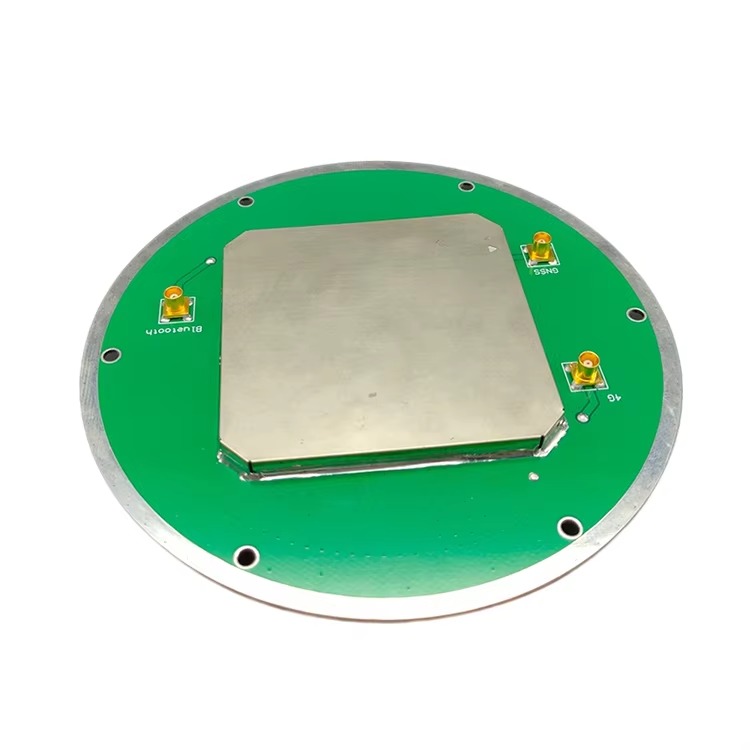
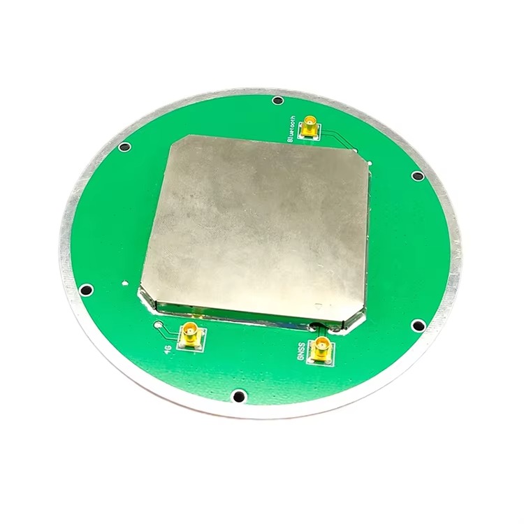
Construction Components
The physical construction of RTK surveying antennas integrates durability with performance, ensuring reliable operation in harsh field conditions:
Radiating Element: The radiating element is the antenna’s signal-capturing core, usually a planar patch array made from high-conductivity materials like gold-plated copper. These patches are etched onto a dielectric substrate (e.g., ceramic or fiberglass-reinforced plastic) with a high dielectric constant, allowing for compact design without sacrificing efficiency. The patch geometry is optimized to resonate at target GNSS frequencies, ensuring maximum signal absorption across all supported bands.
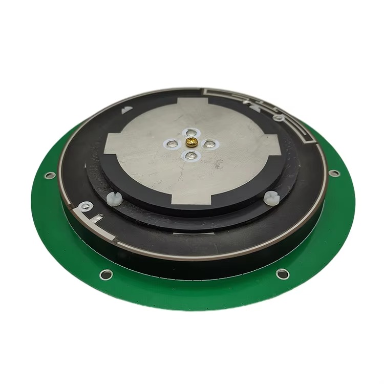
Ground Plane: A large, flat ground plane (typically aluminum or stainless steel) serves as a reflective surface, enhancing gain and shielding the antenna from electromagnetic interference (EMI) from the ground or nearby equipment. For RTK antennas, the ground plane is often larger than that of standard antennas, minimizing multipath interference from reflections off the rover or surrounding objects. It may also include mounting hardware for secure attachment to surveying poles or vehicles.
Low-Noise Amplifier (LNA): Positioned close to the radiating element, the LNA amplifies weak satellite signals (as low as -160 dBm) while adding minimal noise. RTK LNAs have a noise figure of 0.5-2 dB, ensuring that the amplified signal retains a high signal-to-noise ratio (SNR)—critical for resolving the fine phase differences used in RTK calculations. The LNA is often paired with band-pass filters to block out-of-band interference from cellular towers, Wi-Fi, or other radio sources.
Radome and Enclosure: The radome protects internal components from dust, moisture, and physical damage while allowing GNSS signals to pass through with minimal attenuation. Made from materials like fiberglass or UV-resistant plastic, the radome is designed to be transparent to L-band frequencies. For field durability, RTK antennas often have an IP67 or IP68 rating, ensuring operation in heavy rain, snow, or dust. The enclosure may also include thermal management features to stabilize LNA performance in extreme temperatures (-40°C to +70°C).
Connector and Cable: RTK antennas use low-loss coaxial cables (e.g., RG-58 or LMR-195) to transmit signals from the LNA to the receiver. These cables minimize signal attenuation, which is critical for preserving the SNR of weak satellite signals. Connectors are typically TNC or SMA, with weatherproof seals to prevent moisture ingress. Some antennas integrate a bias-tee circuit, allowing the receiver to power the LNA via the same cable that carries the signal, simplifying setup.
RTK surveying antennas operate on the principle of precise carrier-phase measurement, augmented by real-time corrections from a base station. Here’s a detailed breakdown of their operation:
Signal Capture and Initial Processing: The antenna’s radiating element captures GNSS signals from multiple satellites and constellations. These signals are electromagnetic waves modulated with timing data (from atomic clocks on the satellites) and orbital parameters (ephemeris). The multi-frequency design ensures that signals from L1, L2, and other bands are captured simultaneously, each carrying unique information about atmospheric delays.
Amplification and Filtering: Weak signals are passed to the LNA, which amplifies them by 20-30 dB. Band-pass filters remove interference from non-GNSS frequencies, ensuring that only the desired bands reach the receiver. This step is critical because noise or interference could corrupt the carrier-phase measurements, undermining RTK accuracy.
Carrier-Phase Measurement: Unlike consumer GNSS systems, which use code-phase measurements (based on the satellite’s pseudorandom code), RTK relies on carrier-phase measurements. The carrier wave is a high-frequency sine wave (e.g., 1575.42 MHz for GPS L1), and by tracking the phase of this wave, the receiver can calculate the distance to the satellite with millimeter-level precision. The RTK antenna’s stable phase center ensures that these phase measurements are consistent across all satellites.
Reception of Base Station Corrections: The base station, equipped with its own high-precision antenna, calculates the difference between its known position and the position derived from satellite signals. This difference (a vector of errors) is formatted into a correction message (e.g., RTCM or CMR+) and transmitted to the rover. The rover’s antenna receives these corrections via a separate radio or cellular link, which are then processed by the receiver.
Real-Time Error Correction: The receiver uses the base station corrections to adjust the rover’s carrier-phase measurements. This involves resolving the integer ambiguity of the carrier phase—an uncertainty in the number of full wavelength cycles between the satellite and receiver. Once ambiguities are resolved (a process accelerated by multi-frequency data), the receiver calculates the rover’s position with sub-centimeter accuracy. The antenna’s role in this step is to provide stable, low-noise signals that enable the receiver to quickly and reliably resolve ambiguities, even in dynamic environments.
Continuous Position Updates: RTK systems provide position updates at rates of 1-10 Hz, ensuring that the rover’s position is continuously corrected as it moves. The antenna maintains signal lock with multiple satellites, and the receiver updates its calculations using new correction data, ensuring that accuracy is preserved even as environmental conditions change (e.g., passing clouds or varying ionospheric activity).
Advantages of RTK Surveying Antennas
RTK surveying antennas offer a suite of advantages that make them indispensable for high-precision applications:
Sub-Centimeter Accuracy: The most significant advantage is their ability to achieve horizontal accuracy of 1-2 cm and vertical accuracy of 2-5 cm when used with a base station. This level of precision is unmatched by standard GNSS systems and is critical for applications such as cadastral surveying (defining property boundaries), construction staking, and deformation monitoring (tracking small movements in structures like bridges or dams).
Real-Time Data Availability: Unlike post-processing methods (e.g., PPP), RTK provides corrected positions in real time. This allows surveyors to verify measurements immediately, reducing the need for rework and enabling on-site decision-making. For example, construction crews can use RTK-guided equipment to ensure that foundations are laid to exact specifications, avoiding costly errors.
Robust Performance in Diverse Environments: Multi-constellation and multi-frequency support ensures that RTK antennas maintain accuracy even when some satellites are blocked. In urban canyons, where tall buildings obscure parts of the sky, the antenna’s ability to access signals from multiple constellations (e.g., GPS and BeiDou) ensures a sufficient number of satellites for reliable positioning. This versatility reduces downtime and extends the range of viable surveying locations.
Efficiency and Cost Savings: RTK systems streamline surveying workflows by eliminating the need for manual benchmarks or repeated measurements. A single RTK rover can cover large areas quickly, with one-person operation in many cases. Over time, this efficiency reduces labor costs and project timelines, making RTK a cost-effective solution for large-scale projects.
Compatibility with Advanced Workflows: RTK antennas integrate seamlessly with modern surveying tools, including drones, robotic total stations, and GIS software. This compatibility enables advanced workflows such as 3D mapping, machine control, and real-time asset tracking, expanding the scope of projects that can benefit from high-precision positioning.
Challenges and Limitations
Despite their strengths, RTK surveying antennas face several challenges that users must address:
Base Station Dependence: RTK accuracy relies on a nearby base station (typically within 10-20 km). Beyond this range, error correction quality degrades because atmospheric conditions differ between the base and rover. While network RTK (NRTK) systems use multiple base stations to extend coverage, they require subscription fees and reliable cellular connectivity, which may not be available in remote areas.
Signal Interference and Multipath: RTK antennas are susceptible to multipath interference, where signals reflect off buildings, trees, or water before reaching the antenna. This can corrupt carrier-phase measurements, introducing errors. While antenna design (e.g., ground plane shielding) mitigates this, multipath remains a challenge in urban or heavily vegetated areas, requiring careful antenna placement or post-processing filters.
Initialization Time: Resolving integer ambiguities (critical for RTK accuracy) can take several minutes, especially in challenging signal conditions. During this initialization period, the system provides only meter-level accuracy. Loss of signal lock (e.g., due to temporary obstruction) requires re-initialization, which can disrupt workflow.
Cost and Complexity: RTK systems, including antennas, receivers, and base stations, are more expensive than standard GNSS equipment. This upfront cost can be a barrier for small surveying firms. Additionally, RTK requires specialized training to operate, as improper setup (e.g., incorrect base station coordinates) can lead to significant errors.
Environmental Limitations: Extreme weather (e.g., heavy rain, dense fog) or electromagnetic interference (e.g., from power lines or radio towers) can degrade signal quality. While ruggedized antennas withstand physical harshness, signal attenuation in such conditions may reduce accuracy or require temporary shutdowns.
Applications of RTK Surveying Antennas
RTK surveying antennas are used across industries where precision is non-negotiable:
Land Surveying and Cadastre: RTK antennas are the gold standard for defining property boundaries, mapping land parcels, and creating legal surveys. Their sub-centimeter accuracy ensures that boundaries are legally defensible, reducing disputes and supporting land registry systems. Surveyors use RTK to collect data quickly, even in remote areas, replacing time-consuming traditional methods.
Construction and Machine Control: In construction, RTK antennas guide heavy machinery (e.g., excavators, graders) to precise locations, ensuring that earthworks, foundations, and structures adhere to design specifications. This “machine control” reduces rework, minimizes material waste, and accelerates project timelines. RTK-enabled drones also use these antennas to capture 3D site models for progress monitoring.
Precision Agriculture: Farmers use RTK antennas to guide tractors, planters, and harvesters with centimeter-level accuracy. This enables precise seed placement, variable-rate fertilization, and efficient field mapping, boosting yields while reducing input costs. RTK also supports irrigation management, ensuring water is applied only where needed.
Infrastructure Monitoring: RTK antennas monitor the stability of bridges, dams, and pipelines, detecting tiny movements (millimeters per year) that indicate structural stress. Continuous RTK measurements provide early warning of potential failures, allowing for timely maintenance. This application is critical for public safety and infrastructure longevity.
Mining and Quarrying: In mining, RTK antennas optimize resource extraction by guiding drills and haul trucks to exact coordinates. This improves efficiency, reduces overburden removal, and ensures compliance with environmental regulations. RTK also supports mine mapping, tracking stockpiles and monitoring slope stability.
Future Trends
The evolution of RTK surveying antennas is driven by advances in GNSS technology, materials science, and connectivity. Key trends include:
Integration with 5G and Low Earth Orbit (LEO) Satellites: 5G networks will enhance NRTK by enabling faster, more reliable correction data transmission, extending coverage to remote areas. LEO satellite constellations (e.g., Starlink, OneWeb) will provide global, low-latency communication, reducing dependence on ground-based base stations and enabling RTK in previously inaccessible regions.
AI-Powered Error Mitigation: Artificial intelligence (AI) and machine learning algorithms will be integrated into RTK receivers to better detect and filter multipath interference. These algorithms will learn from historical data to predict and correct errors in real time, improving accuracy in challenging environments.
Miniaturization and Energy Efficiency: Next-generation RTK antennas will be smaller and lighter, enabling integration into compact devices such as backpack-mounted rovers, small drones, and IoT sensors. Low-power designs will extend battery life, supporting long-duration surveys in remote areas without access to power.
Multi-Sensor Fusion: RTK antennas will increasingly work with complementary sensors (e.g., LiDAR, inertial measurement units [IMUs]) to fill gaps when GNSS signals are lost. IMUs, for example, can maintain positioning accuracy for short periods during signal blockages, ensuring continuous operation in urban canyons or tunnels.
Increased Automation: Future RTK systems will feature autonomous operation, with rovers navigating predefined paths and adjusting to environmental changes without human intervention. This will further reduce labor costs and improve consistency, making high-precision surveying accessible to a broader range of users.
Conclusion
RTK surveying antennas represent a pinnacle of precision in geospatial measurement, enabling sub-centimeter positioning that underpins critical applications from land surveying to infrastructure monitoring. Their design—optimized for multi-frequency reception, low phase center variation, and robust signal processing—ensures that satellite signals are converted into actionable, accurate data. By working in tandem with base stations and advanced receivers, RTK antennas overcome the limitations of standard GNSS, transforming raw satellite signals into reliable geospatial insights.
While challenges such as base station dependence, multipath interference, and cost persist, ongoing advancements in connectivity (5G, LEO satellites), AI-driven error correction, and sensor fusion are addressing these limitations. As a result, RTK technology is becoming more accessible, versatile, and efficient, expanding its role in emerging fields like autonomous construction and precision agriculture.
In a world where accurate geospatial data is essential for sustainable development, infrastructure resilience, and resource management, RTK surveying antennas will remain indispensable. Their ability to blend real-time precision with field durability ensures that they will continue to drive innovation in surveying and mapping, supporting the next generation of geospatial applications. As technology evolves, RTK antennas will not only maintain their position as a cornerstone of precision measurement but also redefine what is possible in the realm of geospatial accuracy.

 86 0755 2819 9597
Lucy Yang | lucy.y@toxutech.com
Nicole Li | nicole@toxutech.com
Dotty Zhao | sales04@toxutech.com
Global Business Director / Sales Team / Global Operations


 En
En Cn
Cn Korean
 Home >


