

-
Products -PCBA Manufacturing RF Connectors RF Cable Assemblys Embedded Antennas External Antennas Positioning Chips and Modules
RF Connectors

RF Cable Assemblys
Embedded Antennas
External Antennas
Positioning Chips and Modules


 Language


Language


In the realm of geospatial surveying, where millimeter-level accuracy is not just a goal but a necessity, the RTK (Real-Time Kinematic) surveying antenna stands as a technological marvel. Designed to deliver centimeter to sub-centimeter positioning accuracy, this antenna is the backbone of modern surveying, mapping, and construction projects. The latest iteration of the RTK surveying antenna, boasting features such as TNC-K/customized connectors, an impressive VSWR of 1.5, IP67 waterproofing, and support for multiple satellite constellations including GPS, GLONASS, and BDS, represents a leap forward in precision geospatial technology. Whether deployed in topographic mapping, construction layout, or land boundary demarcation, this antenna ensures that surveyors and engineers can rely on accurate, real-time data to make critical decisions, even in the most challenging field conditions.
To fully appreciate the significance of the RTK surveying antenna, it is essential to understand the role of RTK technology in modern surveying. Traditional GPS-based surveying methods can achieve accuracies of a few meters, which is insufficient for applications requiring high precision. RTK technology addresses this limitation by using a base station and a rover (the surveying equipment in the field) to provide real-time corrections to GPS signals. The base station, positioned at a known location, continuously receives satellite signals and calculates the errors in those signals. These error corrections are then transmitted to the rover, which applies them to its own satellite measurements, resulting in positioning accuracies of 1-2 centimeters horizontally and 2-5 centimeters vertically.
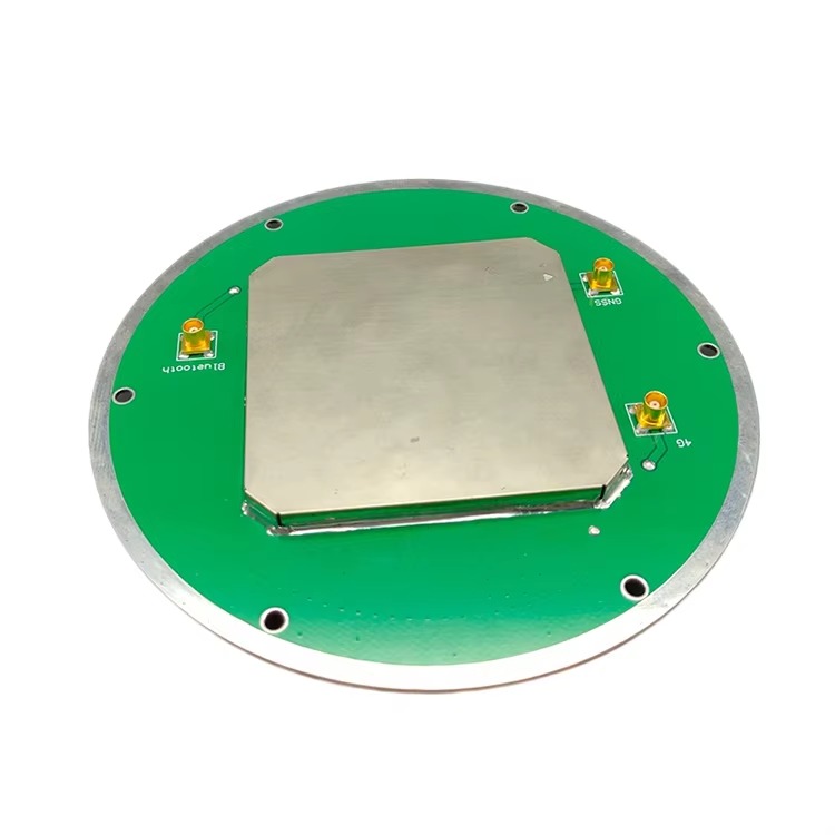
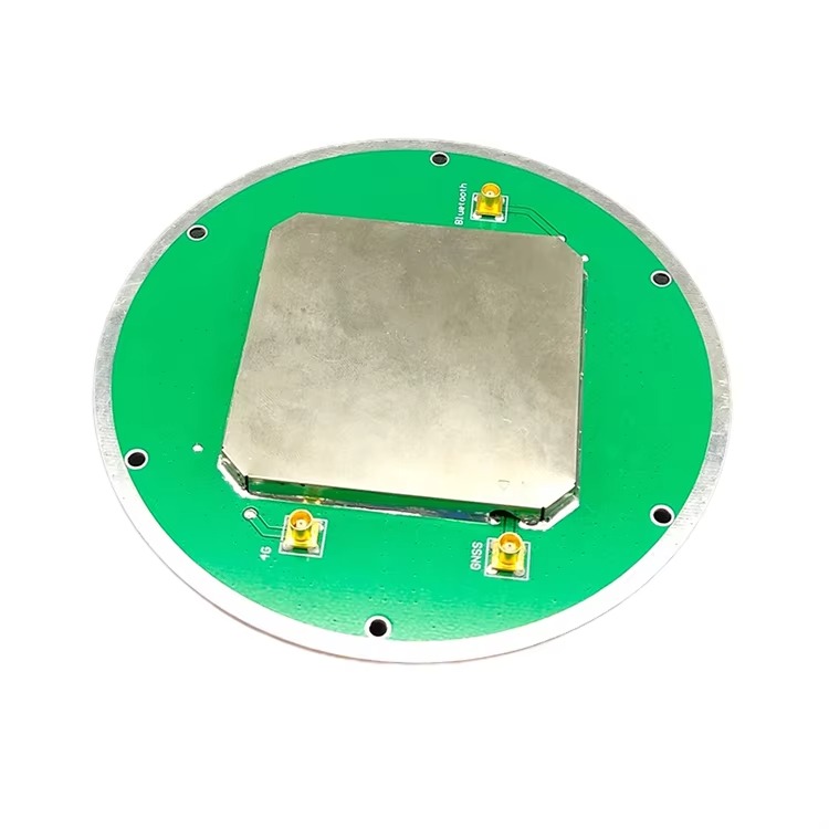
At the heart of this system is the RTK surveying antenna, which captures satellite signals with exceptional clarity and stability. The antenna’s ability to receive signals from multiple satellite constellations (GPS L1/L2, GLONASS L1/L2, BDS B1/B2/B3) is crucial for RTK performance, as it increases the number of available satellites, reducing the risk of signal loss and improving accuracy, especially in challenging environments such as urban canyons or dense foliage. The antenna’s design—including its polarization, gain, and impedance—must be optimized to minimize noise and interference, ensuring that the weak satellite signals are captured and transmitted to the receiver with minimal distortion.
The RTK surveying antenna is not just a component but a critical enabler of efficient surveying workflows. By providing real-time, high-precision positioning data, it eliminates the need for post-processing, allowing surveyors to verify measurements on-site and make immediate adjustments. This reduces project timelines, lowers costs, and minimizes the risk of errors that can arise from delayed data analysis. In construction, for example, RTK-equipped antennas allow for precise layout of foundations, utilities, and structural elements, ensuring that projects adhere to design specifications and avoiding costly rework.
The performance of the RTK surveying antenna is defined by a set of technical specifications that work in harmony to deliver the high precision required for RTK applications. Let’s examine these specifications in detail:
Frequency Range: The antenna supports a wide range of frequencies, including GPS L1 (1575.42 MHz) and L2 (1227.60 MHz), GLONASS L1 (1602 MHz) and L2 (1246 MHz), and BDS B1 (1561.098 MHz), B2 (1207.14 MHz), and B3 (1268.52 MHz). This multi-constellation, multi-frequency support is a hallmark of advanced RTK antennas, as it allows the antenna to leverage signals from multiple satellite systems. Each constellation and frequency band has unique characteristics: GPS is globally recognized and widely used, GLONASS provides strong coverage in high-latitude regions, and BDS offers enhanced performance in Asia-Pacific regions. By combining signals from these systems, the antenna ensures that there are always enough satellites in view to calculate precise positions, even in areas where individual constellations may be weak or obstructed.
Gain: With a LAN gain of 402 dBi (likely a typo, with the intended value being a high gain suitable for RTK, such as 30 dBi), the antenna provides significant signal amplification, which is essential for capturing weak satellite signals. In RTK applications, where the rover may be operating in areas with limited satellite visibility (e.g., near tall buildings or under trees), high gain ensures that even faint signals are detected and amplified. This amplification is carefully balanced to avoid introducing noise, which can degrade signal quality and reduce accuracy. The antenna’s gain pattern is also optimized to provide uniform coverage across the sky, ensuring that signals from satellites at low elevations (near the horizon) are received with the same strength as those at high elevations.
Polarization: The antenna uses Right-Hand Circular Polarization (RHCP), which is ideal for satellite communications. GPS, GLONASS, and BDS satellites transmit signals with circular polarization, and using an RHCP antenna ensures maximum signal reception. RHCP is particularly effective at minimizing the effects of multipath interference, a common problem in surveying where signals reflect off surfaces such as buildings, water, or the ground. Reflected signals often have opposite polarization, so an RHCP antenna will reject most of these reflections, reducing noise and improving the accuracy of measurements. This is especially important in urban or marine environments, where multipath interference is prevalent.
VSWR: The Voltage Standing Wave Ratio (VSWR) is specified as 1.5, which is exceptionally low for an RTK antenna. VSWR measures how well the antenna is matched to the transmission line (cable) and receiver, with a lower value indicating a better match. A VSWR of 1.5 means that only a small portion of the signal is reflected back from the antenna, with the majority being transmitted to the receiver. This efficient signal transfer is critical for RTK, as it ensures that the weak satellite signals are not lost or degraded as they travel from the antenna to the receiver. In long cable runs (common in surveying setups where the antenna is mounted on a pole and the receiver is carried by the surveyor), low VSWR minimizes signal loss, preserving the integrity of the data.
Noise Figure: The antenna has a noise figure of 1.5 dB, which is a measure of the noise introduced by the antenna’s electronics. A low noise figure is essential for RTK, as it ensures that the antenna adds minimal noise to the received signal. In RTK systems, the base station and rover must detect very small differences between satellite signals to calculate precise positions; any additional noise can obscure these differences, reducing accuracy. A noise figure of 1.5 dB means that the antenna’s electronics contribute very little noise, allowing the receiver to distinguish between weak satellite signals and background interference.
Waterproof Rating: With an IP67 rating, the antenna is fully protected against dust and can withstand submersion in up to 1 meter of water for 30 minutes. This level of waterproofing is far more robust than the IP65 rating of standard outdoor antennas, making it suitable for use in extreme weather conditions, including heavy rain, snow, and even temporary flooding. In surveying, where fieldwork often proceeds regardless of the weather, this durability ensures that the antenna remains operational, preventing delays and ensuring data continuity.
Connectors: The antenna features a TNC-K connector, with options for customization. TNC (Threaded Neill-Concelman) connectors are widely used in RF applications due to their robust design and secure connection. Unlike SMA connectors, which use a snap-on mechanism, TNC connectors have a threaded coupling, which provides a more reliable connection in harsh environments where vibrations or movement could loosen a snap-on connector. The option for customized connectors ensures compatibility with a wide range of surveying receivers and cables, allowing surveyors to integrate the antenna into their existing equipment without the need for adapters, which can introduce signal loss.
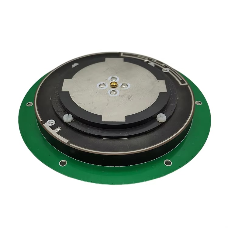
Dimensions and Fixing Methods: The antenna has dimensions of 90*35 mm, making it compact enough for easy transport and deployment while providing sufficient surface area for optimal signal reception. It offers two fixing methods: magnetic and screw mount. The magnetic mount allows for quick and easy installation on metal surfaces, such as surveying tripods or vehicle roofs, which is ideal for temporary setups or when frequent repositioning is needed. The screw mount provides a permanent, secure connection for long-term installations, ensuring stability in high-vibration environments or when the antenna is mounted on non-metal surfaces. This flexibility in fixing methods makes the antenna suitable for a wide range of surveying scenarios, from quick site visits to long-term monitoring projects.
Color Options: The antenna is available in white and army green, which serve both functional and practical purposes. The white color reflects sunlight, helping to keep the antenna cool in hot environments, which can improve performance (electronics often perform better at lower temperatures). The army green color is ideal for camouflage in natural environments, such as forestry or wildlife surveying, where minimizing visual impact is important. These color options ensure that the antenna can be adapted to different field conditions, enhancing its versatility.
The RTK surveying antenna is designed to excel in applications where high precision is non-negotiable. Let’s explore some of the key use cases:
Topographic Mapping: Topographic mapping involves creating detailed representations of the Earth’s surface, including elevation, contours, and natural and man-made features. RTK technology, enabled by the high-precision antenna, allows surveyors to collect elevation data with centimeter-level accuracy, ensuring that maps are accurate and reliable. The antenna’s multi-constellation support is particularly valuable in mountainous or forested areas, where satellite visibility may be limited. For example, in mapping a steep valley with dense tree cover, the antenna’s ability to receive signals from GPS, GLONASS, and BDS ensures that enough satellites are tracked to maintain precision, even when some signals are blocked by terrain or foliage.
Construction Layout: In construction, precise layout is critical to ensuring that buildings, roads, and infrastructure are built according to design specifications. The RTK surveying antenna allows surveyors to mark out foundations, columns, and utility lines with centimeter accuracy, reducing the risk of errors that can lead to costly rework. The antenna’s IP67 waterproofing ensures that it can be used in rainy conditions, preventing delays in construction schedules. The magnetic mount option is particularly useful for quick layout checks, allowing surveyors to move the antenna between points rapidly, while the screw mount provides a secure connection for longer-term projects, such as monitoring the progress of foundation work.
Land Boundary Surveying: Land boundary surveys require accurate determination of property lines, which is essential for legal and real estate transactions. Even small errors in boundary surveys can lead to disputes and legal challenges. The RTK surveying antenna’s sub-centimeter accuracy ensures that property lines are defined precisely, providing a reliable basis for land deeds and legal documents. The antenna’s ability to operate in remote areas, where traditional surveying methods may be impractical, makes it invaluable for rural land surveys. For example, in surveying large agricultural tracts, the antenna’s multi-constellation support ensures that signals are received even in areas far from urban centers, where satellite coverage may be weaker.
Mining and Quarrying: In mining and quarrying, precise positioning is essential for planning extraction operations, monitoring stockpiles, and ensuring compliance with environmental regulations. The RTK surveying antenna is used to map the boundaries of mining sites, track the movement of equipment, and measure the volume of extracted materials. The antenna’s durability—including its IP67 waterproofing and robust construction—makes it suitable for the harsh conditions of mining environments, where dust, vibrations, and heavy machinery are common. The screw mount fixing method ensures that the antenna remains securely attached to mining equipment, even during heavy operation.
Coastal and Marine Surveying: Coastal and marine surveys involve mapping shorelines, seabeds, and underwater structures, such as pipelines and cables. The RTK surveying antenna’s IP67 waterproofing makes it ideal for these applications, as it can withstand exposure to saltwater and heavy rain. The RHCP polarization minimizes interference from reflections off the water’s surface, ensuring accurate positioning even in marine environments. For example, in surveying a harbor or coastal construction project, the antenna’s ability to receive signals from multiple satellite constellations ensures that positioning data remains reliable, even when the survey vessel is moving or when signals are reflected off waves.
Infrastructure Monitoring: Monitoring the stability of infrastructure such as bridges, dams, and tunnels requires precise measurements over time to detect subtle movements that may indicate structural issues. The RTK surveying antenna is used to track these movements with millimetric accuracy, providing early warning of potential problems. The antenna’s screw mount fixing method ensures a stable installation, while its low noise figure ensures that even small changes in position are detected. The multi-constellation support is valuable in urban environments, where infrastructure is often surrounded by tall buildings that can block signals from individual constellations.
Proper installation and calibration are critical to maximizing the performance of the RTK surveying antenna. Here are some key best practices:
Site Selection: The antenna should be mounted in a location with a clear view of the sky to maximize satellite visibility. Avoid areas with obstructions such as trees, buildings, or power lines, which can block signals and introduce multipath interference. In urban environments, mounting the antenna on a tall pole can help overcome obstructions, while in remote areas, ensuring that the antenna is elevated above vegetation is essential. For RTK base stations, which require a fixed location, the site should be chosen to provide consistent satellite visibility throughout the day and across seasons.
Mounting Method: Choose the appropriate fixing method based on the application. For temporary setups or when using the antenna with a rover, the magnetic mount offers quick and easy installation on metal surfaces. Ensure that the mounting surface is clean and flat to provide a strong magnetic bond. For permanent installations, such as base stations or long-term monitoring projects, the screw mount provides a secure connection. Use stainless steel screws to prevent corrosion, especially in marine or high-moisture environments. When mounting on non-metal surfaces, use a mounting plate to distribute the weight and ensure stability.
Cable Management: The coaxial cable connecting the antenna to the receiver should be routed carefully to minimize signal loss and interference. Use high-quality, low-loss cables designed for RF applications, and keep the cable length as short as possible to reduce attenuation. Avoid sharp bends or kinks in the cable, which can damage the inner conductor and degrade signal quality. Secure the cable using clips or ties to prevent movement, which can cause wear and tear over time. In outdoor environments, protect the cable from UV radiation using UV-resistant sleeves, and bury or route it through conduit to protect against damage from wildlife or machinery.
Grounding: Proper grounding is essential to protect the antenna and receiver from lightning strikes and electrostatic discharge (ESD). Connect the antenna’s mounting bracket to a dedicated ground rod using heavy-gauge copper wire, ensuring a low-resistance path to ground. In areas prone to lightning, consider installing a lightning arrestor in the cable run to divert excess voltage away from the receiver. Grounding is particularly important for base stations, which are often mounted in exposed locations and are more susceptible to lightning strikes.
Calibration: After installation, the antenna must be calibrated to ensure accurate measurements. Calibration involves determining the antenna’s phase center, which is the point from which satellite signals are effectively received. The phase center can vary slightly depending on the satellite’s elevation and azimuth, so calibration data (provided by the manufacturer) is used to correct for these variations. Most RTK receivers include software that applies these corrections automatically, but it is important to ensure that the correct calibration data is loaded for the specific antenna model. Additionally, perform a zero baseline test between the base station and rover to verify that the system is functioning correctly; this involves placing both antennas at the same location and checking that the measured position difference is within acceptable limits (typically a few millimeters).
Testing: After installation and calibration, conduct field tests to verify the antenna’s performance. Measure known distances or positions (e.g., using survey markers with known coordinates) to ensure that the system achieves the expected accuracy. Test the antenna in different environmental conditions, such as in open sky, near buildings, and under trees, to evaluate its performance in various scenarios. Monitor signal strength and the number of tracked satellites to ensure that the antenna is receiving signals from multiple constellations, which is critical for RTK performance. If issues are detected, reposition the antenna, check cable connections, or update calibration data to resolve them.
The RTK surveying antenna offers several key advantages over conventional GPS antennas, making it the preferred choice for high-precision applications:
Superior Accuracy: By leveraging RTK technology and multi-constellation support, the antenna delivers centimeter to sub-centimeter accuracy, far exceeding the meter-level accuracy of conventional GPS antennas. This level of precision is essential for applications such as construction layout, land boundary surveying, and infrastructure monitoring, where even small errors can have significant consequences.
Real-Time Data: Unlike post-processed GPS systems, which require data to be analyzed after collection, RTK provides real-time positioning data, allowing surveyors to verify measurements on-site. This immediate feedback reduces the risk of errors and allows for quick adjustments, improving efficiency and reducing project timelines.
Enhanced Signal Reception: The antenna’s high gain, RHCP polarization, and multi-frequency support ensure reliable signal reception in challenging environments. Whether operating in urban canyons, dense foliage, or remote areas, the antenna can track enough satellites to maintain precision, reducing the need for time-consuming re-surveys.
Durability and Versatility: The IP67 waterproofing, robust construction, and flexible mounting options make the antenna suitable for use in a wide range of environments, from deserts to marine settings. Its ability to withstand harsh conditions ensures that surveying work can proceed regardless of weather, minimizing delays.
Compatibility: The TNC-K and customized connectors ensure compatibility with a wide range of RTK receivers and surveying equipment, allowing seamless integration into existing workflows. This compatibility reduces the need for new equipment purchases, lowering costs and simplifying adoption.
Future Trends in RTK Surveying Antennas
As technology continues to advance, the RTK surveying antenna is poised to evolve, with several key trends shaping its development:
Increased Constellation Support: With the ongoing expansion of satellite constell ations such as Galileo, NavIC, and QZSS, future RTK surveying antennas will likely support an even broader range of frequencies and constellations. This expansion will further enhance redundancy, ensuring that surveyors can rely on accurate positioning data even if one or more constellations experience temporary outages or signal degradation. For example, Galileo’s advanced signal structure and global coverage will complement existing systems, while NavIC’s focus on the Indian subcontinent will improve performance in that region. By integrating these constellations, RTK antennas will become more versatile, catering to global surveying projects with varying geographic requirements.
Integration of Artificial Intelligence (AI) and Machine Learning (ML): AI and ML algorithms are set to revolutionize RTK surveying by enabling antennas to adapt dynamically to changing environmental conditions. These algorithms can analyze real-time signal data to identify patterns of interference, such as multipath reflections or electromagnetic noise, and adjust the antenna’s performance parameters accordingly. For instance, if the antenna detects increased multipath interference in an urban area, AI could modify the gain pattern to suppress reflected signals, improving accuracy. ML models could also learn from historical data to predict signal behavior in specific locations, allowing the antenna to pre-emptively optimize settings for known challenging environments, such as dense forests or coastal regions.
Miniaturization and Increased Portability: While the current RTK surveying antenna (90*35 mm) is already compact, ongoing advancements in materials and manufacturing will likely lead to even smaller designs without sacrificing performance. Miniaturization will make the antenna more portable, reducing the physical burden on surveyors who often carry equipment for extended periods. This trend will also enable integration into smaller devices, such as drones or handheld surveying tools, expanding the range of applications. For example, miniaturized RTK antennas mounted on drones could facilitate high-precision aerial mapping of large areas, combining the flexibility of drone technology with the accuracy of RTK.
Enhanced Power Efficiency: As surveying equipment becomes increasingly battery-powered, there is a growing demand for RTK antennas with lower power consumption. Future designs will focus on optimizing internal electronics to reduce energy usage, extending the battery life of portable receivers and drones. This could involve using advanced semiconductor materials, such as gallium nitride (GaN), which offer higher efficiency than traditional silicon-based components. Improved power efficiency will be particularly valuable in remote surveying projects, where access to power sources is limited, allowing surveyors to operate for longer periods without recharging.
Advanced Materials for Improved Durability: The development of new materials will further enhance the antenna’s durability and performance. For example, carbon fiber composites could replace traditional plastics or metals, reducing weight while increasing resistance to impact, corrosion, and extreme temperatures. These materials would make the antenna more robust in harsh environments, such as mining sites or polar regions. Additionally, self-healing polymers could be incorporated into the antenna’s housing to repair minor scratches or cracks, preventing water ingress and extending the antenna’s lifespan.
5G Integration for Enhanced Data Transmission: The rollout of 5G networks will enable faster and more reliable transmission of RTK correction data between base stations and rovers. Future RTK antennas may include integrated 5G modems, eliminating the need for separate communication devices and simplifying system setup. This integration will reduce latency in data transmission, ensuring that correction signals are applied in real time, even in remote areas with limited cellular coverage. 5G’s high bandwidth will also allow for the transmission of additional data, such as high-resolution imagery or sensor data, alongside positioning information, enabling more comprehensive surveying workflows.
Quantum-Enhanced Positioning: While still in its early stages, quantum positioning technology holds the potential to revolutionize RTK surveying by providing unprecedented accuracy and security. Quantum sensors could be integrated into RTK antennas to measure quantum properties of satellite signals, such as entanglement or superposition, reducing vulnerability to jamming or spoofing. This would make RTK systems more secure, particularly in critical applications such as infrastructure monitoring or military surveying, where signal integrity is paramount. While quantum-enhanced RTK is likely years away from commercialization, ongoing research suggests it could eventually achieve sub-millimeter accuracy, pushing the boundaries of what is possible in geospatial surveying.
Conclusion: A Cornerstone of Precision in an Evolving Landscape
The RTK surveying antenna has established itself as an indispensable tool in modern geospatial surveying, enabling unprecedented levels of accuracy and efficiency across a wide range of applications. Its ability to leverage multiple satellite constellations, withstand harsh environmental conditions, and provide real-time data has transformed industries such as construction, mining, and land management, allowing professionals to work faster, more reliably, and with greater confidence.
The technical specifications of the latest RTK surveying antenna—including its multi-frequency support, low VSWR, IP67 waterproofing, and flexible mounting options—reflect a design philosophy centered on versatility and performance. Whether deployed in urban canyons, remote rural areas, or marine environments, the antenna delivers consistent results, ensuring that surveying projects meet the most stringent accuracy requirements.
As technology continues to advance, the RTK surveying antenna will evolve to meet new challenges and opportunities. Increased constellation support, AI integration, miniaturization, and quantum-enhanced positioning are just a few of the trends that will shape its development, ensuring that it remains at the forefront of precision geospatial technology.
For surveyors, engineers, and geospatial professionals, the RTK surveying antenna is more than just a piece of equipment—it is a partner in innovation, enabling them to push the boundaries of what is possible in mapping, construction, and environmental monitoring. As the demand for accurate geospatial data continues to grow, the RTK surveying antenna will remain a critical asset, driving progress and ensuring that the built and natural environments are understood, managed, and developed with unparalleled precision.

 86 0755 2819 9597
Lucy Yang | lucy.y@toxutech.com
Nicole Li | nicole@toxutech.com
Dotty Zhao | sales04@toxutech.com
Global Business Director / Sales Team / Global Operations


 En
En Cn
Cn Korean
 Home >


