

-
Products -PCBA Manufacturing RF Connectors RF Cable Assemblys Embedded Antennas External Antennas Positioning Chips and Modules
RF Connectors

RF Cable Assemblys
Embedded Antennas
External Antennas
Positioning Chips and Modules


 Language


Language


In the realm of precision positioning, Real-Time Kinematic (RTK) technology represents the gold standard, enabling centimeter-level accuracy in real-time. While the RTK receiver and its complex algorithms often receive the spotlight, the unsung hero of this system is the RTK GNSS Antenna. This specialized component is not a mere passive collector of signals; it is the critical first stage that dictates the ultimate performance ceiling of the entire RTK system. Its function is to act as a highly selective and sensitive gateway, capturing the incredibly faint signals from Global Navigation Satellite Systems (GNSS)—including GPS, GLONASS, Galileo, and BeiDou—while aggressively rejecting errors that would otherwise corrupt the precise measurements required for RTK.
An RTK system works by resolving the integer ambiguity in the carrier-phase measurements of GNSS signals. This process is exceptionally vulnerable to errors, the most significant of which are ionospheric delay and multipath interference. A standard, consumer-grade antenna is omnidirectional and does little to mitigate these issues. In contrast, an RTK GNSS antenna is engineered from the ground up to address these very challenges. Its primary objectives are:
Multi-Constellation, Multi-Frequency Reception: To simultaneously receive signals from all available satellite constellations and across multiple frequency bands (e.g., L1, L2, L5). This multi-frequency capability is paramount, as it allows the receiver to calculate ionospheric-free linear combinations, effectively neutralizing the largest source of signal delay.
Exceptional Phase Center Stability: This is arguably the most critical characteristic. The phase center is the electrical point from which the signal is received. Any movement or variation of this point with changes in signal direction (elevation and azimuth) or frequency introduces errors that directly translate into positional inaccuracies. RTK antennas are meticulously designed and calibrated to have a phase center that is physically and electrically stable.
Advanced Multipath Mitigation: Through specialized ground planes, often incorporating choke ring technology or Artificial Magnetic Conductor (AMC) surfaces, these antennas are designed to reject signals reflected from the ground and surrounding objects. Multipath signals, which travel a longer path than the direct signal, are a primary source of error in precision GNSS.
Low-Noise Amplification: An integrated Low-Noise Amplifier (LNA) is essential. It boosts the extremely weak satellite signals (which are often buried in thermal noise) to a level suitable for transmission through the coaxial cable to the receiver, all while adding minimal additional noise itself. This preservation of the Signal-to-Noise Ratio (SNR) is vital for reliable carrier-phase tracking.
In essence, the RTK GNSS antenna is a high-precision instrument. It sets the foundation upon which RTK is built. Without its ability to provide a clean, stable, and strong signal stream, the receiver's processing engine would be unable to reliably resolve the integer ambiguities, and the promise of real-time, centimeter accuracy would remain unfulfilled. It is the cornerstone of applications ranging from surveying and construction to agriculture and autonomous driving, where precision is not a luxury but a necessity.
The superior performance of an RTK GNSS antenna is a direct consequence of its sophisticated design and precision construction. It is a complex assembly where every material, geometric shape, and electronic component is meticulously chosen and optimized for electrical performance, mechanical stability, and environmental resilience.
1. The Radiating Element:
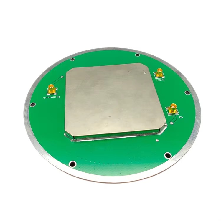
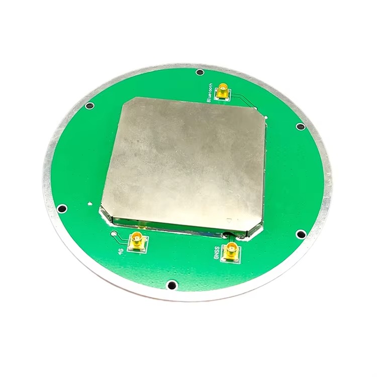
At the heart of the antenna is the radiating element, responsible for the transduction of electromagnetic energy into an electrical current. For RTK applications, the most prevalent design is the microstrip patch antenna. This is typically a circular or square metallic patch etched onto a dielectric substrate. To achieve multi-band operation (e.g., simultaneous reception of L1 and L2 frequencies), a stacked patch configuration is employed. This involves two or more patches of different sizes mounted concentrically, with each patch resonant at a specific frequency band. The patch is fed by a probe or via an aperture coupling mechanism to excite two orthogonal modes with a 90-degree phase shift, generating the required Right-Hand Circular Polarization (RHCP) that matches the polarization of the satellite signals.
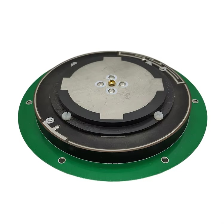
2. The Ground Plane and Multipath Mitigation:
The radiating element is mounted over a ground plane, which is fundamental to defining the antenna's radiation pattern. A simple flat ground plane is insufficient for RTK work. To achieve the necessary rejection of multipath, high-performance antennas use a choke ring structure. This consists of concentric, corrugated metal rings surrounding the radiator. The depth of these rings is precisely engineered to be approximately a quarter-wavelength at the target GNSS frequencies. This creates a high-impedance surface that effectively "chokes" or suppresses surface currents induced by low-elevation, reflected signals. The result is a radiation pattern with high gain towards the zenith (where satellites are) and very low gain (deep nulls) at and below the horizon. Modern alternatives include Artificial Magnetic Conductors (AMCs) or metasurfaces, which provide similar multipath rejection in a much lower-profile, lighter package, ideal for drone-mounted applications.
3. The Low-Noise Amplifier (LNA) and Filtering:
The signals from GNSS satellites are extraordinarily weak, typically around -130 dBm. To prevent these signals from being degraded by the loss in the coaxial cable to the receiver, a Low-Noise Amplifier (LNA) is integrated directly into the antenna housing. This LNA is characterized by two key parameters:
Very Low Noise Figure: Typically between 1-3 dB, meaning it adds almost negligible internal noise to the already weak signal, preserving the crucial Signal-to-Noise Ratio (SNR).
High Gain: Usually 25-40 dB, which boosts the signal power to overcome subsequent cable loss.
To protect the sensitive LNA from powerful out-of-band interference (e.g., from cellular networks, radio, or TV transmitters), bandpass filters are integrated into the RF chain. These filters allow GNSS frequencies to pass unimpeded while strongly attenuating other signals.
4. The Radome:
The entire assembly is protected by a radome. This is not a simple plastic cover but an engineered component made from materials like polycarbonate, ABS, or ceramic-loaded plastics. The material must be RF-transparent, meaning it has minimal signal attenuation and a stable dielectric constant that does not detune the antenna's carefully optimized performance. It must also be mechanically robust, waterproof (often rated to IP67 or higher), and resistant to UV degradation.
5. Calibration and Phase Center Stability:
After manufacture, each antenna model undergoes rigorous calibration in an anechoic chamber. Its phase center variation (PCV) is measured across a full sphere of elevation and azimuth angles for each frequency band. This data is used to generate an antenna model file (e.g., in ANTEX format). During RTK processing, this model is applied to correct the measurements for the known phase center offsets and variations. This calibration is what separates a surveying-grade RTK antenna from a generic one; it ensures the electrical reference point is treated as a stable, known point, which is non-negotiable for centimeter-level accuracy.
The operation of an RTK GNSS antenna is a sophisticated process involving electromagnetic reception, frequency selection, spatial filtering, and electronic amplification, all working in concert to deliver a pristine signal to the receiver.
1. Capturing Circular Polarization:
GNSS satellites transmit RHCP signals. The antenna's patch element is designed to be inherently sensitive to this rotation. The feed mechanism excites two degenerate orthogonal modes with a 90-degree phase difference, creating a radiating electromagnetic field that rotates clockwise. This provides perfect reciprocity for receiving the incoming RHCP waves, ensuring maximum efficiency. Conversely, it offers inherent rejection of Left-Hand Circularly Polarized (LHCP) waves, which are typically generated by signal reflections, providing a first layer of multipath mitigation.
2. Frequency Selection and Multi-Band Operation:
The stacked patch design is a multi-resonant structure. The upper, smaller patch is primarily resonant at higher frequencies (e.g., L1), while the larger, lower patch is resonant at lower frequencies (e.g., L2). The careful electromagnetic coupling between them allows for efficient operation across a wide bandwidth. The integrated bandpass filters further ensure that only the desired GNSS frequency spectrum reaches the LNA, protecting it from powerful out-of-band signals that could cause saturation or generate intermodulation products that drown out the weak GNSS signals.
3. Spatial Filtering via Radiation Pattern Shaping:
The choke ring or AMC ground plane performs the critical function of spatial filtering. It shapes the antenna's radiation pattern to be hemispherical. It provides high gain for signals arriving from above the horizon (direct satellite signals) and creates deep nulls for signals arriving from at or below the horizon (where multipath reflections originate). When a multipath signal attempts to induce currents on the ground plane, the choke rings present a very high impedance, effectively blocking these currents and preventing the energy from being coupled into the antenna's feed. This is the most effective form of analog multipath suppression.
4. Signal Amplification and Noise Management:
The captured signal power is at the level of the thermal noise floor. The integrated LNA's role is to amplify this signal without significantly degrading the SNR. Because it is mounted directly at the antenna, it amplifies the weak signal before the signal suffers from cable loss. The cable loss would attenuate both the signal and the incoming noise equally, but it would also add its own thermal noise. By placing the high-gain LNA at the source, the signal is boosted to a level where the subsequent cable loss has a much less detrimental effect on the overall system noise figure. The LNA's low noise figure ensures it adds almost no additional noise itself.
5. Delivery to the RTK Receiver:
The final output of the antenna is an amplified, filtered, and clean multi-band signal, delivered via the coaxial cable to the RTK receiver. The receiver's sophisticated algorithms then track the code and, more importantly, the carrier phase of these signals. The antenna's job is to provide the highest quality raw material—the signal—for this processing. The receiver uses the multi-frequency phase data to form ionospheric-free combinations and resolve the integer ambiguities, ultimately calculating a position with centimeter accuracy. The stability of the antenna's phase center is absolutely critical throughout this process, as any uncalibrated movement would be interpreted by the receiver as a change in the satellite-to-antenna range.
Advantages:
Enables Centimeter-Level Accuracy: The primary advantage is the fundamental enabling of RTK technology. Without the antenna's stable phase center and multipath rejection, achieving reliable centimeter-level accuracy in real-time would be impossible.
Rapid and Reliable Integer Ambiguity Resolution: By providing clean, multi-frequency data, the antenna drastically reduces the time required for the RTK engine to fix integer ambiguities (initialization). It also makes this fix more reliable and robust.
Superior Multipath Rejection: The specialized ground plane design provides a significant advantage in environments prone to reflections, such as urban canyons, near buildings, or on open water, where standard antennas would fail.
Long Baseline Performance: The ability to correct for ionospheric delay using multi-frequency measurements allows RTK systems to maintain accuracy over much longer baselines (tens of kilometers) between the rover and base station.
Improved Satellite Availability and Geometry: Support for all constellations and frequencies increases the number of visible satellites, improving availability in obstructed environments and providing better satellite geometry (lower DOP values), which enhances accuracy.
Challenges:
High Cost: The complex design, precision materials, rigorous manufacturing, and mandatory calibration make RTK GNSS antennas significantly more expensive than consumer-grade antennas.
Size and Weight: Traditional choke ring designs are physically large and heavy. While AMC-based designs are more compact, there is always a trade-off between performance and Size, Weight, and Power (SWaP), which is critical for applications like drones.
Power Requirements: The integrated LNA requires a power source, which is typically supplied from the receiver through the coaxial cable (phantom power). This adds to the system's overall power consumption.
Calibration Dependency: To achieve their stated accuracy, these antennas require precise antenna phase center variation (PCV) models. Using an incorrect model, or no model at all, can introduce systematic errors of several centimeters. Users must ensure their processing software uses the correct model for their specific antenna.
Susceptibility to Interference: While they have filters, extremely strong and nearby interferers (e.g., a cellular transmitter) can still overload the LNA, causing saturation and loss of tracking. Sophisticated jamming and spoofing signals are also a growing threat.
Design Complexity for Full Band Coverage: Covering all modern signals (L1, L2, L5, etc.) requires a very wide bandwidth, which presents significant design challenges in maintaining stable performance, consistent phase center, and good impedance matching across the entire spectrum.
Applications:
The applications for RTK GNSS antennas are vast and critical to numerous industries:
Surveying and Geodesy: The traditional application for high-precision land surveying, cadastral mapping, and establishing control networks.
Precision Agriculture: Guiding autonomous tractors for planting, spraying, and harvesting with centimeter accuracy to optimize input use and maximize yield.
Construction and Machine Control: Providing the precise position for bulldozers, graders, and excavators for grade checking and autonomous operation, reducing rework and saving time.
Unmanned Aerial Vehicles (UAVs): Enabling centimeter-accurate PPK (Post-Processed Kinematic) and RTK for drones used in aerial mapping, photogrammetry, and LiDAR surveys.
Autonomous Vehicles and Robotics: Serving as a primary sensor for localization in self-driving cars, trucks, and agricultural robots.
Monitoring and Deformation Analysis: Monitoring the structural health of dams, bridges, buildings, and landslides for minute movements indicating potential failure.
Marine and Hydrographic Surveying: Precise positioning for port construction, dredging operations, and bathymetric mapping.
Future Trends:
Tighter Integration with IMUs: The future lies in deeply integrated "GNSS/INS" modules where the antenna is combined with a high-grade inertial measurement unit (IMU) within a single housing. This provides a continuous navigation solution that maintains accuracy during GNSS outages.
Advanced Anti-Jamming and Anti-Spoofing (AJA): Integrating adaptive antenna arrays capable of forming nulls in the direction of jammers or identifying and rejecting spoofed signals. This is critical for safety-critical applications.
Ultra-Compact, High-Performance Designs: Continued innovation in metamaterials (e.g., metasurfaces) will lead to antennas that offer choke-ring-level performance in a form factor no larger than a standard patch antenna.
AI-Enhanced Performance: Using embedded processing and machine learning to dynamically characterize the antenna's environment in real-time, adapting its pattern or processing to further suppress multipath or interference.
Multi-Sensor Fusion Hubs: The antenna will evolve into a central "smart antenna" hub that also acts as a reference for UWB, WiFi, and other local positioning technologies.
Cost Reduction and Mass Market Adoption: As manufacturing techniques improve, the cost of RTK technology will continue to fall, making it accessible for consumer applications like smartphone positioning, augmented reality, and personal mobility devices.
Conclusion
The RTK GNSS antenna is a masterpiece of electromagnetic engineering and a foundational pillar of modern high-precision positioning. It is the critical differentiator that transforms the ubiquitous capability of GNSS from a meter-level utility into a millimeter-level measurement science. Its sophisticated design, focused on phase center stability, multipath mitigation, and low-noise amplification, is dedicated to a single purpose: capturing the faint whispers of satellite signals with utmost purity and integrity.
While challenges of cost, size, and susceptibility to interference remain, the relentless drive for higher accuracy in increasingly compact and demanding applications ensures that RTK antenna technology will continue to evolve. The future points towards smarter, smaller, and more integrated systems that will further embed centimeter-accurate positioning into the fabric of our technological world. From autonomous machines that build our cities and grow our food to the scientific instruments that monitor the dynamics of our planet, the RTK GNSS antenna will remain the indispensable, albeit often unseen, gatekeeper of precision.

 86 0755 2819 9597
Lucy Yang | lucy.y@toxutech.com
Nicole Li | nicole@toxutech.com
Dotty Zhao | sales04@toxutech.com
Global Business Director / Sales Team / Global Operations


 En
En Cn
Cn Korean
 Home >


