

-
Products -PCBA Manufacturing RF Connectors RF Cable Assemblys Embedded Antennas External Antennas Positioning Chips and Modules
RF Connectors

RF Cable Assemblys
Embedded Antennas
External Antennas
Positioning Chips and Modules


 Language


Language


In the evolving landscape of precision positioning technology, RTK (Real-Time Kinematic) GNSS Antennas with Tilt Compensation have emerged as a game-changing solution, addressing a long-standing challenge in field surveying: the impact of antenna tilt on positioning accuracy. Traditional RTK GNSS antennas require precise leveling to ensure the antenna’s phase center aligns with the vertical axis, as even a small tilt (as little as 1–2 degrees) can introduce horizontal positioning errors of several centimeters— a critical issue for applications demanding centimeter-level accuracy. RTK GNSS Antennas with Tilt Compensation integrate specialized sensors and algorithms to automatically detect and correct for antenna tilt, eliminating the need for manual leveling and expanding the versatility of RTK technology across diverse industries.
The core value of these antennas lies in their ability to maintain high-precision positioning even when mounted on non-level surfaces or moving platforms. In field surveying, for example, surveyors often work on uneven terrain— such as slopes, construction sites with debris, or remote areas with rocky ground— where manually leveling a traditional RTK antenna is time-consuming, labor-intensive, and prone to human error. A tilt-compensated RTK GNSS antenna, by contrast, can be quickly mounted on a pole or vehicle, and its internal sensors (typically accelerometers or inclinometers) will immediately measure the antenna’s tilt angle relative to the horizontal plane. This tilt data is then used to mathematically correct the GNSS positioning calculations, ensuring that the final position output remains accurate to within 1–2 centimeters, even if the antenna is tilted by up to 15–20 degrees.
The demand for RTK GNSS Antennas with Tilt Compensation has grown rapidly in recent years, driven by the expansion of applications that require mobility and flexibility. Industries such as construction, agriculture, mining, and UAV (Unmanned Aerial Vehicle) surveying are key adopters. In construction, for instance, tilt-compensated antennas are mounted on excavators, graders, and bulldozers, allowing operators to work on sloped terrain without stopping to level the antenna— a change that reduces equipment downtime by 20–30% compared to traditional RTK systems. In precision agriculture, farmers use tilt-compensated antennas on sprayers and harvesters, which often operate on hilly fields; the antennas ensure that the equipment’s position is accurately tracked, enabling precise application of fertilizers or pesticides and reducing waste by up to 15%.
Historically, tilt compensation was a feature limited to high-end surveying equipment, such as total stations, but advances in MEMS (Micro-Electro-Mechanical Systems) sensor technology have made it accessible for GNSS antennas. Early attempts to add tilt compensation to RTK antennas relied on external inclinometers, which were bulky, expensive, and required separate calibration. However, modern tilt-compensated RTK GNSS antennas integrate miniaturized MEMS accelerometers directly into the antenna enclosure, reducing size and cost while improving reliability. These MEMS sensors can measure tilt angles with an accuracy of 0.1 degrees or better, providing the precision needed to correct GNSS positioning errors.
Another key aspect of the overview is the integration of tilt compensation with multi-constellation GNSS reception. Modern RTK GNSS Antennas with Tilt Compensation support multiple satellite constellations— including GPS, GLONASS, Galileo, and BeiDou— which enhances signal availability and accuracy, especially in challenging environments such as urban canyons or dense forests. The combination of multi-constellation support and tilt compensation makes these antennas highly versatile, capable of delivering reliable performance in a wide range of conditions. As industries continue to prioritize efficiency, mobility, and precision, the role of RTK GNSS Antennas with Tilt Compensation will only become more critical, solidifying their position as a cornerstone technology in modern geospatial measurement.
2.1 Core Components of Tilt-Compensated RTK GNSS Antennas
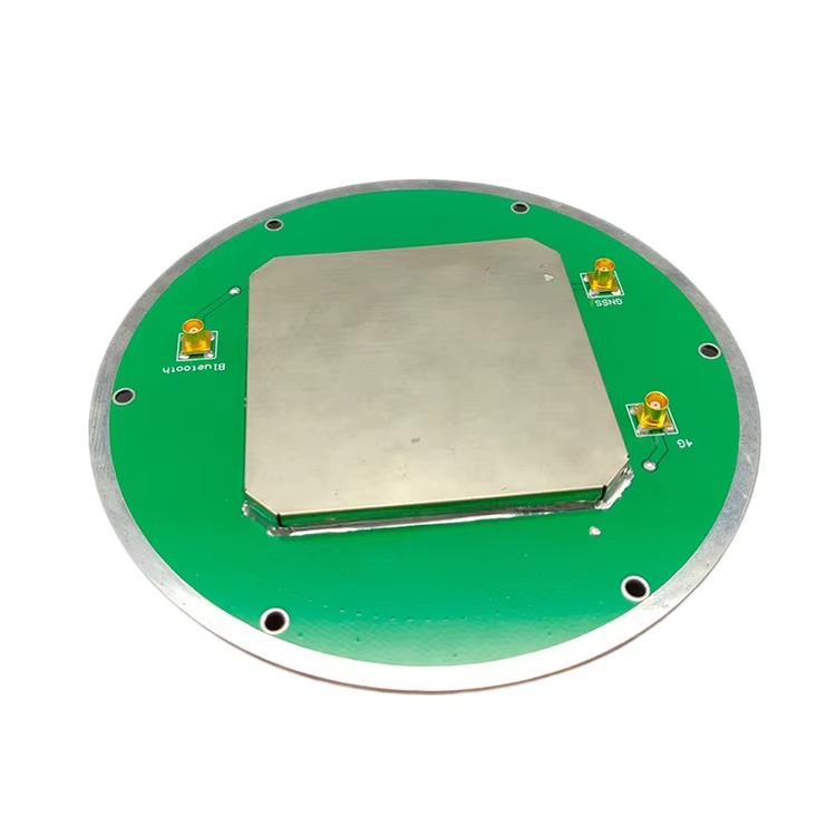
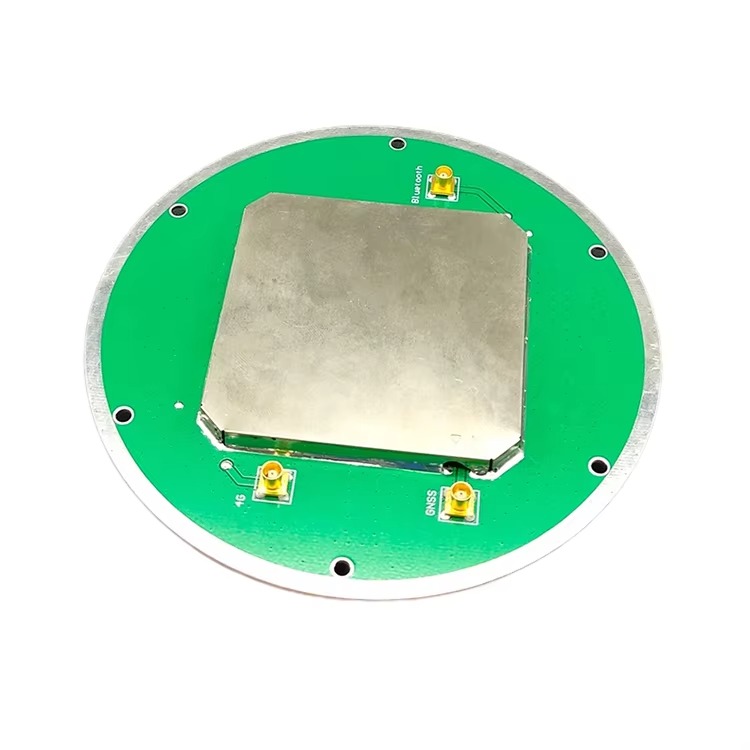
RTK GNSS Antennas with Tilt Compensation are engineered with a unique set of components that work together to achieve both high-precision GNSS positioning and automatic tilt correction. These components include the GNSS antenna element, MEMS tilt sensors (accelerometers or inclinometers), a signal processing unit, a calibration module, and a rugged enclosure. Each component is carefully designed to ensure compatibility, reliability, and performance.
The GNSS antenna element is the foundation of the system, responsible for receiving signals from multiple satellite constellations and frequency bands. Unlike standard RTK antennas, which may use a single patch element, tilt-compensated antennas often employ multi-element arrays (such as patch arrays or quadrifilar helix antennas) to improve signal reception and phase center stability. Patch arrays are a common choice due to their compact size and low profile; they consist of multiple rectangular conductive patches printed on a dielectric substrate (e.g., Teflon or FR4), with a ground plane beneath. Each patch is tuned to receive signals from specific GNSS frequencies (e.g., L1, L2, L5 for GPS; B1, B2 for BeiDou), and the array configuration ensures that the antenna can capture signals from satellites at different elevation angles, even when tilted. The phase center of the array is carefully calibrated to minimize variation, as even small phase center shifts can introduce positioning errors that tilt compensation cannot fully correct.
The MEMS tilt sensor is the key component that enables tilt compensation. Most modern tilt-compensated RTK antennas use 3-axis MEMS accelerometers, which measure the acceleration due to gravity to determine the antenna’s orientation relative to the horizontal plane. A 3-axis accelerometer can detect tilt in both the pitch (forward-backward) and roll (left-right) axes, with some advanced models also supporting yaw (rotation around the vertical axis) measurement— though yaw correction typically requires additional sensors, such as a magnetometer or gyroscope. The MEMS accelerometer is mounted directly onto the antenna’s circuit board, in close proximity to the GNSS antenna element, to ensure that the tilt measurements accurately reflect the orientation of the phase center. These sensors have a resolution of 0.01 degrees or better and a range of ±20 degrees, which covers the typical tilt angles encountered in field applications.
The signal processing unit is responsible for integrating data from the GNSS antenna element and the MEMS tilt sensor. It consists of a microcontroller or digital signal processor (DSP) that performs two key tasks: processing the GNSS signals to calculate the raw positioning data, and applying the tilt correction algorithm to adjust this data based on the sensor’s tilt measurements. The GNSS signal processing involves amplifying the weak satellite signals using a low-noise amplifier (LNA), filtering out interference with band-pass filters, and demodulating the signals to extract satellite ephemeris data and carrier-phase measurements. The tilt correction algorithm uses trigonometric calculations to adjust the raw GNSS position— for example, if the antenna is tilted by 10 degrees in the pitch axis, the algorithm calculates the horizontal displacement caused by this tilt and subtracts it from the raw position output. The processing unit also handles communication with external devices, such as RTK base stations or data loggers, via interfaces like USB, Ethernet, or wireless (Bluetooth, Wi-Fi, or cellular).
The calibration module is essential for ensuring the accuracy of the tilt compensation. MEMS accelerometers can drift over time due to temperature changes, vibration, or aging, which can lead to incorrect tilt measurements. The calibration module addresses this by performing regular self-calibration or allowing manual calibration by the user. Self-calibration typically involves the antenna measuring its tilt when placed on a known level surface (e.g., during startup) and adjusting the sensor’s output to match the expected zero-tilt value. Manual calibration may be required in extreme environments, where the antenna is exposed to high temperatures or vibration; the user places the antenna on a level surface and triggers a calibration routine, which updates the sensor’s offset values. Some advanced models also include temperature compensation, using a built-in temperature sensor to adjust the accelerometer’s output based on ambient temperature— a feature that reduces tilt measurement errors by up to 50% in temperature extremes ranging from -40°C to 85°C.
2.2 Enclosure Design for Durability and Performance
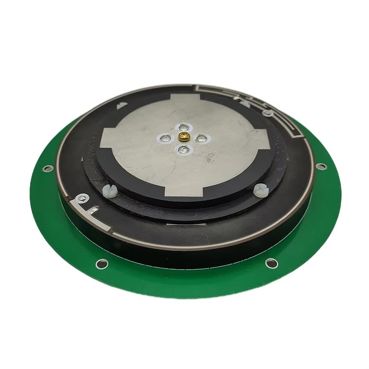
The enclosure of an RTK GNSS Antenna with Tilt Compensation is designed to protect the internal components from environmental damage while ensuring that the GNSS signals and tilt sensor measurements are not compromised. The enclosure must balance three key requirements: ruggedness, signal transparency, and sensor accuracy.
Ruggedness is critical for field applications, where the antenna may be exposed to dust, moisture, vibration, and physical impact. Most tilt-compensated RTK antennas feature an IP (Ingress Protection) rating of IP67 or higher— IP67 means the antenna is dust-tight and can withstand immersion in 1 meter of water for 30 minutes, while IP68 allows for deeper submersion. The enclosure is typically made of high-performance materials such as reinforced polycarbonate, fiberglass-reinforced plastic (FRP), or aluminum alloy. Reinforced polycarbonate is lightweight and impact-resistant, making it suitable for handheld or UAV-mounted antennas; FRP offers superior corrosion resistance, ideal for marine or coastal applications; and aluminum alloy provides excellent thermal conductivity, helping to dissipate heat from the internal electronics, which is important for antennas used in high-temperature environments.
Signal transparency is essential for the GNSS antenna element, as the enclosure material must not block or attenuate the satellite signals. The top portion of the enclosure (the radome) is made of a dielectric material with a low dielectric constant (typically between 2.0 and 3.0) and low loss tangent (less than 0.005 at GNSS frequencies). Common radome materials include Teflon, polyethylene, and ABS plastic. These materials allow GNSS signals to pass through with minimal attenuation— typically less than 0.5 dB— ensuring that the antenna can receive weak signals from low-elevation satellites. The radome’s shape is also optimized to minimize signal reflection and diffraction; a hemispherical or low-profile design is preferred, as it reduces the likelihood of signal bouncing off the radome surface and causing multipath interference.
Sensor accuracy is influenced by the enclosure’s design, as vibration or thermal expansion can affect the MEMS accelerometer’s measurements. To mitigate this, the enclosure includes vibration-damping features, such as rubber gaskets or foam inserts, which absorb shocks and reduce the transfer of vibration from the mounting surface to the internal circuit board. The MEMS accelerometer is also mounted on a rigid sub-board, which is isolated from the enclosure’s walls to prevent thermal expansion of the enclosure from warping the sensor’s position. In addition, the enclosure’s thermal design is optimized to maintain a stable internal temperature; some models include heat sinks or passive cooling vents to prevent the internal electronics from overheating, which could degrade the accelerometer’s performance. For example, an antenna used in desert environments may have a heat-dissipating aluminum base that draws heat away from the circuit board, keeping the accelerometer within its operating temperature range of -40°C to 85°C.
2.3 Mounting and Integration Features
RTK GNSS Antennas with Tilt Compensation are designed to be easily mounted on a variety of platforms, including survey poles, vehicles, UAVs, and fixed structures. The mounting design must be secure, adjustable, and compatible with standard mounting hardware, while also ensuring that the tilt sensor’s measurements are accurate.
For survey pole mounting— a common use case in field surveying— the antenna features a 5/8-inch x 11-threaded base, which is the industry standard for survey poles. The base is reinforced to withstand the weight of the antenna and the pole, and it includes a locking nut to secure the antenna in place. Some models also include a bubble level (even though tilt compensation eliminates the need for manual leveling) to provide a visual reference for the user, helping to ensure that the antenna is not tilted beyond its compensation range (typically 15–20 degrees). The antenna’s center of gravity is positioned close to the mounting point to reduce the risk of the pole tipping over, especially when used on uneven terrain.
For vehicle mounting— such as on construction equipment or agricultural machinery— the antenna includes a magnetic base or a bolt-on bracket. Magnetic bases are ideal for temporary installations, as they can be quickly attached and removed without drilling; they feature strong neodymium magnets that can hold the antenna in place even when the vehicle is moving over rough terrain. Bolt-on brackets are used for permanent installations, such as on the roof of a grader or harvester; they are made of steel or aluminum and include multiple mounting holes to accommodate different vehicle designs. The mounting bracket is also designed to isolate the antenna from vehicle vibration, using rubber bushings or shock absorbers to reduce the impact of vibrations on the MEMS accelerometer.
For UAV mounting— a rapidly growing application— the antenna is designed to be lightweight and compact, with a weight of less than 100 grams in some cases. It features a quick-release mounting system that is compatible with standard UAV payload bays, allowing for easy integration with drones of various sizes. The antenna’s low profile is critical for UAV applications, as it reduces wind resistance and minimizes the impact on the drone’s flight stability. Some UAV-mounted tilt-compensated antennas also include a built-in IMU (Inertial Measurement Unit) that combines accelerometers, gyroscopes, and magnetometers; this IMU works with the tilt compensation feature to provide even more accurate positioning data, especially during the drone’s takeoff and landing, when tilt angles can change rapidly.
Integration with external systems is another key design feature. RTK GNSS Antennas with Tilt Compensation include a range of communication interfaces to connect to RTK base stations, data loggers, or control systems. Wireless interfaces such as Bluetooth 5.0 or Wi-Fi 6 allow for easy connection to handheld devices, such as tablets or smartphones, enabling users to configure the antenna, view real-time positioning data, and perform calibration. Wired interfaces like USB-C or Ethernet are used for high-speed data transfer, which is important for applications that require continuous logging of positioning data, such as long-term structural monitoring. Some advanced models also support cellular connectivity (4G LTE or 5G), allowing the antenna to receive RTK correction data from a cloud-based base station network— a feature that eliminates the need for a local base station and expands the antenna’s range of operation.
3.1 Fundamentals of RTK GNSS Positioning
To understand the working principle of RTK GNSS Antennas with Tilt Compensation, it is first necessary to review the basics of RTK GNSS positioning. RTK technology uses a base station and a rover antenna (the tilt-compensated antenna) to achieve centimeter-level accuracy. The base station is installed at a known position, where it continuously receives GNSS signals and measures the time it takes for each signal to travel from the satellite to the base station antenna. Using its known position, the base station calculates the expected signal travel time and compares it to the measured travel time; the difference between these two values is the “error correction,” which includes errors caused by atmospheric delays (ionospheric and tropospheric), satellite clock inaccuracies, and orbital errors. The base station transmits this correction data to the rover antenna via a communication link (e.g., UHF radio, cellular, or Wi-Fi).
The rover antenna (RTK GNSS Antenna with Tilt Compensation) receives the GNSS signals and the correction data from the base station. It uses the correction data to adjust its own GNSS measurements, eliminating the common errors that affect both the base station and the rover. The key to RTK accuracy is the use of carrier-phase measurements: instead of measuring the time delay of the satellite’s code signal (used in standard GPS), RTK measures the phase of the satellite’s carrier wave (a higher-frequency signal with a shorter wavelength, e.g., 19 cm for GPS L1). The carrier-phase measurement is much more precise, but it is ambiguous— it only provides the fractional part of the wave’s phase, not the total number of full wavelengths between the satellite and the antenna. To resolve this ambiguity, the rover uses the base station’s correction data to compare the carrier-phase measurements from both antennas, allowing it to determine the correct number of wavelengths. Once the ambiguities are resolved, the rover can calculate its position with an accuracy of 1–2 cm horizontally and 2–5 cm vertically.
3.2 How Tilt Compensation Corrects Positioning Errors
The core innovation of RTK GNSS Antennas with Tilt Compensation is their ability to detect and correct for errors introduced by antenna tilt. When a traditional RTK antenna is tilted, the phase center of the antenna is no longer directly above the point being measured (the “ground point”), which introduces a horizontal positioning error. The magnitude of this error depends on two factors: the tilt angle (θ) and the height of the antenna above the ground (h, known as the “antenna height”). The error (E) can be calculated using the formula: E = h × sin(θ). For example, if the antenna is mounted on a 2-meter pole and tilted by 10 degrees, the horizontal error is 2 × sin(10°) ≈ 0.347 meters— a significant error that renders the RTK data useless for high-precision applications.
Tilt-compensated RTK GNSS antennas eliminate this error by using MEMS accelerometers to measure the tilt angle (θ) and then applying a mathematical correction to the GNSS position. The process involves three key steps: tilt measurement, error calculation, and position correction.
Step 1: Tilt Measurement
The MEMS accelerometer integrated into the antenna measures the acceleration due to gravity along its three axes (x, y, z). When the antenna is level, the z-axis (vertical) measures the full force of gravity (9.81 m/s²), and the x and y axes (horizontal) measure zero. When the antenna is tilted, the force of gravity is distributed across the axes: for example, if the antenna is tilted forward (pitch) by θ degrees, the z-axis acceleration decreases by cos(θ), and the x-axis acceleration increases by sin(θ). The accelerometer’s signal processing unit uses these measurements to calculate the tilt angles in the pitch (θ_pitch) and roll (θ_roll) axes. Most accelerometers can measure tilt angles with an accuracy of 0.1 degrees or better, which is sufficient to calculate the positioning error with a precision of a few millimeters. Some advanced antennas also use sensor fusion—combining data from the accelerometer with a gyroscope—to reduce noise in tilt measurements, especially when the antenna is mounted on moving platforms (e.g., a vibrating UAV or construction vehicle). The gyroscope measures angular velocity, which helps the system distinguish between actual tilt and temporary vibrations, ensuring that the tilt angle calculation remains stable.
Step 2: Error Calculation
Once the tilt angles (θ_pitch and θ_roll) are measured, the signal processing unit calculates the horizontal positioning error caused by the tilt. This error is broken down into two components: the error along the north-south axis (E_NS) and the error along the east-west axis (E_EW), which correspond to the pitch and roll directions, respectively. For pitch tilt, the error along the direction of the tilt (e.g., north if tilted forward) is calculated as E_pitch = h × sin(θ_pitch), where h is the antenna height (measured by the user or automatically detected via a built-in rangefinder in some models). Similarly, for roll tilt, the error along the lateral direction (e.g., east if tilted to the right) is E_roll = h × sin(θ_roll). These errors are then converted into coordinate system adjustments—using the antenna’s known orientation relative to geographic north (determined via a magnetometer or GNSS heading data)—to align with the RTK system’s north-east-up (NEU) coordinate frame.
For example, if an antenna is mounted on a 1.8-meter pole, tilted 8 degrees forward (pitch) toward the north, and 5 degrees to the right (roll) toward the east, the error calculations would be:
E_pitch (north direction) = 1.8 × sin(8°) ≈ 1.8 × 0.139 ≈ 0.25 meters (25 cm)
E_roll (east direction) = 1.8 × sin(5°) ≈ 1.8 × 0.087 ≈ 0.157 meters (15.7 cm)
These values represent the horizontal displacement between the antenna’s phase center (measured by GNSS) and the actual ground point being surveyed.
Step 3: Position Correction
The final step involves applying the calculated errors to the raw RTK position data to produce the corrected position. The raw RTK position (P_raw_N, P_raw_E, P_raw_U) represents the coordinates of the antenna’s phase center. To get the corrected position of the ground point (P_corr_N, P_corr_E, P_corr_U), the error values are subtracted from the raw coordinates (since the raw position is offset by the tilt-induced error):
P_corr_N = P_raw_N - E_pitch (north error)
P_corr_E = P_raw_E - E_roll (east error)
P_corr_U = P_raw_U - h (vertical correction, to adjust from the antenna’s height to the ground level)
Using the previous example, if the raw RTK position is (500000 m N, 300000 m E, 150 m U), the corrected position would be:
P_corr_N = 500000 - 0.25 = 499999.75 m N
P_corr_E = 300000 - 0.157 = 299999.843 m E
P_corr_U = 150 - 1.8 = 148.2 m U
This corrected position accurately represents the ground point, eliminating the tilt-induced errors that would have plagued a traditional RTK antenna. The entire process—from tilt measurement to position correction—occurs in real time, with a latency of less than 100 milliseconds, ensuring that the antenna’s output is synchronized with the RTK system’s update rate (typically 1–10 Hz).
3.3 Integration of Tilt Data with RTK Calculations
A critical aspect of the working principle is the seamless integration of tilt data with the RTK carrier-phase calculations. Unlike post-processing solutions that apply tilt correction after the fact, RTK GNSS Antennas with Tilt Compensation correct the position in real time, which requires tight synchronization between the GNSS receiver and the tilt sensor.
The integration begins with time synchronization: both the GNSS receiver and the MEMS accelerometer are clocked using the same reference (typically the GNSS receiver’s 1 PPS—pulse per second—signal). This ensures that the tilt measurements and GNSS measurements are time-stamped identically, avoiding errors caused by time delays between the two systems. For example, if the GNSS receiver takes a position measurement at time t, the tilt sensor’s data at exactly time t is used for correction, not data from t+10 ms, which could reflect a different tilt angle (especially on moving platforms).
Next, the tilt data is integrated into the RTK ambiguity resolution process. In traditional RTK systems, ambiguity resolution relies on the assumption that the base station and rover antennas are both level, so the baseline (distance between the two antennas) is calculated based on vertical phase center alignment. When the rover antenna is tilted, the raw baseline calculation is slightly distorted, as the rover’s phase center is offset horizontally. Tilt-compensated antennas address this by correcting the rover’s phase center position before the baseline is calculated. This ensures that the ambiguity resolution process uses accurate baseline data, reducing the time required to resolve ambiguities (known as “time to first fix,” or TTFF) and improving the reliability of the fix in challenging signal conditions.
For example, in a forestry survey where the rover antenna is tilted by 12 degrees due to uneven terrain, a traditional RTK system might struggle to resolve ambiguities because the distorted baseline data creates inconsistencies between the base and rover measurements. A tilt-compensated antenna, by contrast, corrects the rover’s phase center position first, providing a accurate baseline that matches the base station’s data. This can reduce TTFF by 30–50% and increase the likelihood of maintaining a fixed ambiguity solution (critical for centimeter-level accuracy) in areas with weak satellite signals.
Another key integration point is the handling of dynamic tilt—tilt angles that change rapidly, such as when the antenna is mounted on a UAV during takeoff or a construction vehicle navigating a steep slope. In these cases, the tilt sensor’s update rate (typically 100–1000 Hz) is much higher than the GNSS receiver’s update rate (1–10 Hz). To ensure that the tilt correction remains accurate between GNSS measurements, the signal processing unit uses interpolation to estimate the tilt angle at the exact time of each GNSS measurement. For example, if the GNSS receiver updates every 1 second and the tilt sensor updates every 10 milliseconds, the system interpolates the 100 tilt measurements between two GNSS points to find the tilt angle at the 1-second mark. This interpolation uses linear or polynomial methods to minimize error, ensuring that even dynamic tilt is corrected with precision.
4.1 Key Advantages of RTK GNSS Antennas with Tilt Compensation
4.1.1 Reduced Field Work Time and Labor Costs
The most impactful advantage of these antennas is their ability to eliminate manual leveling, a time-consuming and labor-intensive step in traditional RTK surveying. Manual leveling requires surveyors to adjust the antenna’s position using bubble levels or electronic levels, often taking 2–5 minutes per setup— a significant delay when working on large projects with hundreds of survey points. Tilt-compensated antennas, by contrast, can be set up in 30 seconds or less: the user simply mounts the antenna on a pole or vehicle, and the system automatically detects and corrects for tilt. This reduces setup time per point by 80–90%, directly translating to faster project completion and lower labor costs.
A case study from a highway construction project in the United States illustrates this impact. The project required surveying 500+ ground control points along a 20-kilometer stretch of road. Using traditional RTK antennas, the survey team (two people) completed the work in 5 days, spending 70% of their time on manual leveling. When the team switched to tilt-compensated antennas, they completed the same work in 2 days with the same number of people— a 60% reduction in project time. The labor cost savings alone amounted to $12,000, not including savings from reduced equipment rental time.
In addition, tilt-compensated antennas reduce the need for highly skilled surveyors. Manual leveling requires training to master, as even small mistakes can lead to costly errors. Tilt-compensated antennas, however, automate the correction process, allowing less experienced field workers to collect accurate data. This expands the pool of available labor and reduces training costs for companies, especially in regions where skilled surveyors are in short supply.
4.1.2 Improved Accuracy in Dynamic and Uneven Environments
Traditional RTK antennas struggle to maintain accuracy in environments where the antenna cannot be leveled— such as sloped terrain, moving vehicles, or vibrating platforms. Tilt-compensated antennas, by contrast, deliver consistent centimeter-level accuracy even in these challenging conditions, opening up RTK technology to new applications.
In precision agriculture, for example, farm equipment like sprayers and harvesters often operate on hilly fields with slopes of 10–15 degrees. A traditional RTK antenna mounted on a sprayer would introduce errors of 20–30 cm per pass, leading to over-spraying in some areas and under-spraying in others. A tilt-compensated antenna corrects these errors in real time, ensuring that the sprayer applies fertilizers or pesticides only where needed. A study by the Agricultural Engineering Department at a European university found that tilt-compensated antennas reduced chemical waste by 18% compared to traditional RTK systems, while also improving crop yields by 5% due to more uniform application.
For UAV surveying, dynamic tilt is a constant challenge: drones pitch and roll during flight to maintain altitude and navigate obstacles. A traditional RTK antenna on a UAV would produce positioning errors of 10–20 cm during turns or altitude changes. Tilt-compensated antennas, however, use their high-update-rate sensors to correct for these rapid tilt changes, delivering 1–2 cm accuracy even during aggressive flight maneuvers. This has enabled new UAV applications, such as high-precision 3D mapping of construction sites or power line inspections, where even small positioning errors could lead to incorrect measurements or missed defects.
4.1.3 Enhanced Versatility and Platform Compatibility
RTK GNSS Antennas with Tilt Compensation are highly versatile, compatible with a wide range of mounting platforms— from handheld survey poles to heavy machinery, UAVs, and marine vessels. This versatility stems from their compact design, low power consumption, and ability to handle dynamic tilt, making them suitable for applications where traditional RTK antennas would be impractical.
In marine surveying, for example, tilt-compensated antennas are mounted on boats or buoys to collect bathymetric data (underwater depth measurements). Boats pitch and roll with waves, creating constant tilt that would render traditional RTK antennas useless. Tilt-compensated antennas correct for this tilt in real time, ensuring that the GNSS position of the boat (and thus the underwater sonar data) is accurate to within 2 cm. A marine survey company in Australia used tilt-compensated antennas to map a 50-square-kilometer coastal area, completing the project in half the time of their previous surveys (which used traditional RTK antennas and required frequent stops to level the antenna). The company also reported a 40% reduction in data post-processing time, as the tilt-corrected data required fewer adjustments.
In mining, tilt-compensated antennas are mounted on haul trucks and loaders to track the movement of materials and optimize mining operations. These vehicles operate on rough, sloped terrain, and vibrations from the machinery would disrupt traditional RTK systems. Tilt-compensated antennas withstand these vibrations and correct for tilt, providing accurate positioning data that is used to manage truck routes, monitor material volumes, and improve safety. A coal mine in South Africa reported a 12% increase in daily coal production after implementing tilt-compensated antennas, as the accurate positioning data allowed for more efficient routing of haul trucks and reduced idle time.
4.2 Critical Challenges of RTK GNSS Antennas with Tilt Compensation
4.2.1 Limited Tilt Compensation Range
A major limitation of current tilt-compensated RTK antennas is their restricted tilt range— typically 15–20 degrees. Beyond this range, the MEMS accelerometer’s accuracy degrades, and the trigonometric correction algorithm becomes less effective, leading to increased positioning errors. This limits their use in applications where tilt angles exceed 20 degrees, such as steep mountain surveying, extreme off-road vehicle operations, or UAVs performing aggressive aerobatic maneuvers.
For example, in alpine surveying (mapping mountainous terrain with slopes of 25–30 degrees), tilt-compensated antennas may introduce errors of 5–10 cm, which is unacceptable for high-precision applications like glacier monitoring or avalanche risk assessment. Survey teams in these areas are forced to use traditional RTK antennas with specialized leveling equipment, which is heavy, expensive, and time-consuming to set up.
Manufacturers are working to expand the tilt range by using more advanced MEMS sensors (such as 6-axis IMUs that combine accelerometers and gyroscopes) and improved correction algorithms. Some prototype models can handle tilt angles of up to 30 degrees, but these are currently expensive and not widely available. Until the tilt range is expanded, the versatility of these antennas will remain limited in extreme terrain or high-dynamic applications.
4.2.2 Sensitivity to Vibration and Environmental Factors
While tilt-compensated antennas are designed to be rugged, their MEMS accelerometers are sensitive to high-frequency vibrations and extreme environmental conditions, which can degrade tilt measurement accuracy. In applications with intense vibration— such as construction equipment (e.g., jackhammers, pile drivers) or off-road vehicles on rocky terrain— the accelerometer may mistake vibration for tilt, leading to incorrect correction values and positioning errors.
A test conducted by a construction equipment manufacturer found that a tilt-compensated antenna mounted on a pile driver (which generates vibrations of 50–100 Hz) produced positioning errors of 8–12 cm, compared to 1–2 cm when the same antenna was mounted on a stable surface. To mitigate this, some antennas include vibration filtering algorithms, but these can introduce latency in the tilt correction, which is problematic for dynamic applications.
Extreme temperatures and moisture can also affect performance. MEMS accelerometers have an operating temperature range of typically -40°C to 85°C, but in environments beyond this range (e.g., polar regions with temperatures of -50°C or desert areas with surface temperatures of 95°C), the sensor’s accuracy can drop by 10–20%. Similarly, while most antennas have an IP67 or IP68 rating, prolonged exposure to saltwater (e.g., marine surveys) can corrode the accelerometer’s internal components, leading to drift over time. A marine survey company reported that their tilt-compensated antennas required calibration every 3 months in saltwater environments, compared to every 6 months in freshwater— adding maintenance costs and downtime.
4.2.3 Higher Cost and Complexity
RTK GNSS Antennas with Tilt Compensation are more expensive than traditional RTK antennas, primarily due to the cost of integrating MEMS sensors, calibration modules, and advanced signal processing units. A tilt-compensated RTK antenna typically costs 30–50% more than a comparable non-tilt-compensated model— a significant barrier for small businesses, independent surveyors, or projects with tight budgets.
For example, a traditional RTK antenna may cost \(1,500–\)2,000, while a tilt-compensated version of the same antenna costs \(2,200–\)3,000. For a small surveying firm that needs 5–10 antennas, this cost difference can add up to \(10,000–\)15,000, which may be unaffordable. As a result, many small businesses continue to use traditional RTK antennas, even though they are less efficient, because the upfront cost savings outweigh the long-term productivity benefits.
In addition, the increased complexity of tilt-compensated antennas requires more advanced technical support and maintenance. Unlike traditional antennas, which have few moving parts and require minimal calibration, tilt-compensated antennas need regular calibration of the MEMS sensor, software updates for the correction algorithm, and troubleshooting of sensor-related issues. This requires specialized knowledge that many field workers lack, leading to increased reliance on manufacturer support or trained technicians. A survey of independent surveyors found that 60% reported struggling with calibration or sensor issues at least once per project, with 40% saying they had to contact the manufacturer for support— causing delays of 1–2 days per issue.
5.1 Current Applications Across Industries
5.1.1 Construction and Infrastructure Development
The construction industry is the largest adopter of RTK GNSS Antennas with Tilt Compensation, using them to streamline site layout, machine guidance, and structural monitoring. In site layout— the process of marking the position of buildings, roads, and utilities on the ground— tilt-compensated antennas eliminate the need for manual leveling, allowing surveyors to mark points 2–3 times faster than with traditional RTK. For example, during the construction of a residential subdivision, a survey team using tilt-compensated antennas can mark the location of 100 house foundations in a single day, compared to 30–40 with traditional antennas. This speedup reduces the time between design approval and construction start, accelerating project timelines.
Machine guidance is another key application. Tilt-compensated antennas are mounted on excavators, graders, and pavers to guide operators in real time, ensuring that the machinery follows the design plans with centimeter-level accuracy. On sl
oped terrain, such as a highway construction site with slopes of 8–12 degrees, a grader equipped with a tilt-compensated antenna can precisely shape the roadbed to the required elevation without frequent stops for manual leveling. A construction company in Canada reported that using tilt-compensated antennas on their grading fleet reduced the time required to prepare a 5-kilometer highway section by 25%, from 4 weeks to 3 weeks. The antennas also reduced material waste by 10%, as the grader’s precise movements ensured that only the necessary amount of soil was removed or added.
Structural monitoring is a growing application for tilt-compensated antennas, especially for large-scale infrastructure like bridges, dams, and skyscrapers. These structures can experience small movements over time due to temperature changes, wind, or soil settlement, and monitoring these movements requires high-precision positioning. Tilt-compensated antennas are mounted on the structure’s surface, where they can operate even if the mounting point is slightly tilted (e.g., due to minor structural movement). The antennas continuously collect position data, which is analyzed to detect any abnormal shifts. For example, a bridge monitoring project in Europe used 12 tilt-compensated antennas to track the bridge’s movement over a 2-year period. The antennas detected a 3-millimeter lateral shift during high winds, which was within the safe range, but also identified a 5-millimeter settlement in one pier— prompting early maintenance that prevented further damage. The project demonstrated that tilt-compensated antennas are more reliable than traditional monitoring systems, which often require manual leveling and can miss small movements.
5.1.2 Precision Agriculture
Precision agriculture relies on accurate positioning to optimize crop yields, reduce resource waste, and minimize environmental impact— and RTK GNSS Antennas with Tilt Compensation have become a key enabler of this technology. In agricultural applications, the antennas are mounted on a variety of equipment, including tractors, sprayers, harvesters, and planters, where they operate on hilly fields and uneven terrain.
One of the most common uses is in variable-rate application (VRA) of fertilizers, pesticides, and water. VRA systems use GNSS positioning to map the field’s soil fertility and crop health, then adjust the amount of inputs applied to each area based on this data. For this to work, the equipment’s position must be accurate to within a few centimeters— even on slopes. A traditional RTK antenna on a sprayer would introduce errors on hilly terrain, leading to over-application in some areas and under-application in others. Tilt-compensated antennas correct these errors, ensuring that the VRA system applies the right amount of inputs exactly where needed. A study by the U.S. Department of Agriculture (USDA) found that farmers using tilt-compensated antennas in VRA systems reduced fertilizer use by 12–15% while increasing crop yields by 4–6%, compared to farmers using traditional RTK or GPS systems.
Another application is in auto-steer systems for tractors and harvesters. Auto-steer systems use GNSS positioning to guide the equipment along a pre-planned path, reducing operator fatigue and ensuring that the equipment covers the field without overlapping or missing areas. On uneven terrain, a traditional auto-steer system with a non-tilt-compensated antenna may drift off course, leading to overlapping passes that waste fuel and time. Tilt-compensated antennas keep the auto-steer system on track, even on slopes of up to 15 degrees. A farmer in Iowa, USA, reported that using a tilt-compensated antenna on his tractor’s auto-steer system reduced overlapping passes by 8%, saving approximately 10 hours of work and 50 gallons of fuel per season on a 500-acre farm.
Planters also benefit from tilt-compensated antennas, as they ensure that seeds are planted at the correct depth and spacing— critical factors for germination and crop growth. On sloped fields, a traditional planter’s depth control system may be thrown off by the terrain, leading to uneven planting. A tilt-compensated antenna provides accurate positioning data that the planter’s control system uses to adjust the depth of the seed drills in real time. A study by a leading agricultural equipment manufacturer found that planters equipped with tilt-compensated antennas had a 95% seed spacing accuracy on slopes, compared to 80% for planters with traditional RTK antennas. This improved accuracy led to more uniform crop emergence and a 3–4% increase in yield.
5.1.3 UAV Surveying and Mapping
The rise of UAVs (drones) in surveying and mapping has created a high demand for compact, lightweight, and accurate GNSS antennas— and RTK GNSS Antennas with Tilt Compensation have become the preferred choice for high-precision UAV applications. UAVs experience constant tilt during flight (pitch and roll) as they adjust their altitude, navigate obstacles, and turn— making traditional RTK antennas unsuitable, as they would produce large positioning errors. Tilt-compensated antennas correct for this dynamic tilt, delivering centimeter-level accuracy that is essential for applications like 3D modeling, construction site monitoring, and land surveying.
One of the most important UAV applications is in construction site mapping. Construction companies use UAVs equipped with cameras and LiDAR sensors to capture high-resolution images and 3D point clouds of the site, which are used to track progress, detect errors, and compare the actual construction to the design plans. For this data to be useful, each pixel in the image or point in the point cloud must be tagged with an accurate GNSS position. A UAV with a traditional RTK antenna would produce positioning errors of 10–20 cm during flight, leading to inaccuracies in the 3D model. A tilt-compensated antenna reduces these errors to 1–2 cm, ensuring that the model accurately reflects the site’s conditions. A construction company in the United Kingdom used a UAV with a tilt-compensated antenna to map a 10-acre construction site every week. The accurate 3D models allowed the company to detect a 5-centimeter misalignment in a concrete foundation early, saving $50,000 in rework costs.
UAVs with tilt-compensated antennas are also used in land surveying, especially in remote or difficult-to-access areas like forests, mountains, and wetlands. Traditional ground surveying in these areas is time-consuming and dangerous, but UAVs can cover large areas quickly and safely. The tilt-compensated antenna ensures that the UAV’s position is accurate even when flying over uneven terrain or in windy conditions. A surveying firm in Brazil used a UAV with a tilt-compensated antenna to survey a 50-square-kilometer forest reserve. The firm completed the survey in 3 days, compared to 2 weeks using traditional ground surveying methods. The survey data was used to create a detailed map of the reserve’s vegetation and topography, which was critical for a conservation project.
Another emerging UAV application is in power line and pipeline inspection. UAVs equipped with cameras and sensors inspect power lines for damage, corrosion, or vegetation encroachment— tasks that were previously done by workers in helicopters or on foot. The UAV’s position must be accurate to within a few centimeters to ensure that the inspection covers every part of the line and that any defects are mapped correctly. Tilt-compensated antennas provide this accuracy, even when the UAV is flying close to power lines and making quick, dynamic movements to avoid obstacles. A utility company in Germany reported that using UAVs with tilt-compensated antennas reduced power line inspection time by 60% and improved the detection rate of small defects (like cracked insulators) by 30%, compared to traditional inspection methods.
5.2 Future Trends Shaping RTK GNSS Antennas with Tilt Compensation
5.2.1 Integration with Advanced Sensor Fusion
The future of tilt-compensated RTK GNSS antennas lies in the integration of more advanced sensor fusion technologies, which will improve their accuracy, reliability, and ability to handle extreme conditions. Currently, most tilt-compensated antennas use 3-axis accelerometers to measure tilt, but future models will combine these accelerometers with other sensors— such as gyroscopes, magnetometers, and even LiDAR— to create a more robust positioning system.
Sensor fusion with gyroscopes (to create 6-axis IMUs) will address the current limitation of vibration sensitivity. Gyroscopes measure angular velocity, which allows the system to distinguish between actual tilt and temporary vibrations. For example, when a tilt-compensated antenna is mounted on a vibrating construction vehicle, the gyroscope will detect the vehicle’s vibration frequency and filter out these signals from the accelerometer data, ensuring that only true tilt is used for correction. This will reduce positioning errors in high-vibration environments by 50–70%, making the antennas suitable for use on equipment like jackhammers and pile drivers.
Adding magnetometers (to create 9-axis IMUs) will improve the antenna’s ability to determine its orientation relative to geographic north, which is critical for converting tilt errors into the correct coordinate system adjustments. Currently, some antennas rely on GNSS heading data to determine orientation, but this can be inaccurate in areas with weak satellite signals (e.g., urban canyons or dense forests). Magnetometers provide a direct measurement of magnetic north, which is more reliable in these conditions. Sensor fusion of accelerometers, gyroscopes, and magnetometers will ensure that the antenna’s tilt correction is accurate even when GNSS signals are poor— expanding its use in challenging environments.
Integration with LiDAR sensors is another promising trend, especially for UAV and mobile mapping applications. LiDAR sensors capture detailed 3D data of the surrounding environment, which can be used to verify and correct the GNSS positioning data. For example, a UAV equipped with a tilt-compensated RTK antenna and a LiDAR sensor can use the LiDAR data to detect changes in the terrain (e.g., a sudden slope) and adjust the tilt correction algorithm in real time. This hybrid system will provide even higher accuracy— potentially sub-centimeter— and will be useful in applications like precision mapping of historical sites or monitoring of small structural movements.
5.2.2 Expansion of Tilt Compensation Range and Environmental Resilience
Manufacturers are investing heavily in expanding the tilt compensation range of RTK GNSS antennas, with the goal of covering tilt angles of up to 30–40 degrees. This will be achieved through two key innovations: more advanced MEMS accelerometers and improved correction algorithms.
Next-generation MEMS accelerometers will have a wider dynamic range and higher accuracy, allowing them to measure tilt angles of up to 40 degrees with an error of less than 0.1 degrees. These accelerometers will use new materials and manufacturing techniques, such as silicon carbide (SiC) or gallium nitride (GaN), which are more resistant to temperature changes and vibration. For example, a SiC-based accelerometer can operate in temperatures ranging from -60°C to 125°C, compared to -40°C to 85°C for traditional silicon accelerometers— making it suitable for use in polar regions, deserts, and industrial environments.
Improved correction algorithms will also play a role in expanding the tilt range. Current algorithms use simple trigonometric calculations (E = h × sin(θ)) to correct for tilt, but these become less accurate at angles above 20 degrees due to the nonlinear relationship between tilt angle and positioning error. Future algorithms will use more complex mathematical models, such as polynomial regression or machine learning (ML) models, to calculate errors at higher tilt angles. ML models, in particular, will be trained on large datasets of tilt and positioning data, allowing them to adapt to different environments and tilt scenarios. For example, an ML-based algorithm could learn to correct for tilt in a UAV during aggressive turns, where the tilt angle changes rapidly, by recognizing patterns in the sensor data.
Environmental resilience will also be a key focus of future development. Manufacturers will improve the antenna’s resistance to saltwater, dust, and vibration by using new enclosure materials and sealing technologies. For example, some future antennas may use a ceramic radome instead of plastic, which is more resistant to corrosion and UV radiation. Sealing technologies like laser welding will replace traditional gaskets, creating a hermetic seal that prevents moisture and dust from entering the enclosure— improving the antenna’s IP rating to IP69 (which withstands high-pressure water jets) or higher. These improvements will extend the antenna’s lifespan in harsh environments, reducing maintenance costs and downtime.
5.2.3 Miniaturization and Low-Power Design for Edge Devices
As the Internet of Things (IoT) and edge computing grow in popularity, there will be a demand for smaller, lower-power RTK GNSS Antennas with Tilt Compensation that can be integrated into edge devices— such as wearable sensors, small UAVs, and smart agricultural equipment. Miniaturization and low-power design will be key trends in the coming years, driven by advancements in microelectronics and energy-efficient technologies.
Miniaturization will be achieved through the development of smaller MEMS sensors and integrated circuits (ICs). For example, a next-generation MEMS accelerometer could be as small as 1 mm × 1 mm, compared to 3 mm × 3 mm for current models. Integrated circuits will also become more compact, with the GNSS receiver, tilt sensor, and signal processing unit combined into a single chip (a system-on-chip, or SoC). This will reduce the antenna’s size by 50–70%, making it suitable for use in wearable devices like smart glasses for surveyors. A surveyor wearing smart glasses with a miniaturized tilt-compensated antenna could see real-time positioning data overlaid on their field of view, allowing them to mark survey points without carrying a separate antenna or receiver.
Low-power design will be critical for edge devices, which often run on batteries and need to operate for long periods without recharging. Future tilt-compensated antennas will use energy-efficient components, such as low-power LNAs and microcontrollers, and will incorporate power management techniques like duty cycling. Duty cycling involves turning off non-essential components (e.g., the tilt sensor) when the antenna is not in use, then waking them up quickly when needed. For example, an antenna used in a smart agricultural sensor could wake up every 10 minutes to take a position measurement, then go back to sleep— reducing power consumption by 80–90% compared to a continuously operating antenna.
Another low-power technology is energy harvesting, which allows the antenna to generate its own power from the environment. For example, a tilt-compensated antenna mounted on a tractor could use vibration energy harvesting to convert the tractor’s vibration into electricity, powering the antenna without relying on a battery. Solar energy harvesting could also be used for antennas mounted on UAVs or fixed structures, with a small solar panel integrated into the radome. These technologies will make tilt-compensated antennas more sustainable and reduce their reliance on disposable batteries— a key benefit for remote applications where battery replacement is difficult.
Conclusion
RTK GNSS Antennas with Tilt Compensation have transformed the field of precision positioning, addressing a critical limitation of traditional RTK systems: the need for manual leveling. By integrating MEMS tilt sensors and real-time correction algorithms, these antennas deliver centimeter-level accuracy even on uneven terrain, moving platforms, and in dynamic environments— opening up RTK technology to a wide range of applications across construction, agriculture, UAV surveying, and marine industries.
Throughout this examination, we have seen how the design and construction of these antennas— from their multi-element GNSS arrays and 3-axis MEMS accelerometers to their rugged enclosures and versatile mounting systems— are optimized for performance and reliability. Their working principles, which combine RTK carrier-phase positioning with real-time tilt error calculation and correction, ensure that even small tilt angles do not compromise accuracy. The advantages of these antennas are clear: they reduce field work time and labor costs by eliminating manual leveling, improve accuracy in dynamic environments, and enhance versatility across multiple platforms. A highway construction project, for example, cut survey time by 60% using tilt-compensated antennas, while a precision farmer reduced fertilizer use by 15% and increased yields by 6%— demonstrating their tangible impact on productivity and sustainability.
However, challenges remain. The limited tilt compensation range (15–20 degrees) restricts their use in extreme terrain, while sensitivity to vibration and environmental factors can degrade performance in harsh conditions. Higher costs and complexity also present barriers for small businesses and budget-constrained projects. These challenges, however, are being addressed through ongoing innovations: advanced sensor fusion (combining accelerometers, gyroscopes, and LiDAR) to improve accuracy and vibration resistance, new materials and algorithms to expand the tilt range and environmental resilience, and miniaturization and low-power design to integrate the antennas into edge devices.
Looking ahead, the future of RTK GNSS Antennas with Tilt Compensation is bright. As sensor fusion, ML-based correction algorithms, and energy harvesting technologies mature, these antennas will become even more accurate, reliable, and accessible. They will play a key role in the growth of precision agriculture, smart construction, and autonomous systems— enabling new applications that we can only begin to imagine, such as fully autonomous UAVs for precision mapping or self-driving agricultural equipment that operates seamlessly on hilly terrain.
In conclusion, RTK GNSS Antennas with Tilt Compensation are more than just a technical innovation— they are a catalyst for efficiency, sustainability, and safety in industries that rely on precision positioning. By eliminating the need for manual leveling and adapting to dynamic environments, they have made high-precision GNSS technology more accessible and practical than ever before. As technology continues to advance, these antennas will remain at the forefront of precision geospatial measurement, driving progress and innovation for years to come.

 86 0755 2819 9597
Lucy Yang | lucy.y@toxutech.com
Nicole Li | nicole@toxutech.com
Dotty Zhao | sales04@toxutech.com
Global Business Director / Sales Team / Global Operations


 En
En Cn
Cn Korean
 Home >


