

-
Products -PCBA Manufacturing RF Connectors RF Cable Assemblys Embedded Antennas External Antennas Positioning Chips and Modules
RF Connectors

RF Cable Assemblys
Embedded Antennas
External Antennas
Positioning Chips and Modules


 Language


Language


In the world of high-precision geospatial measurement, even the smallest signal distortion can lead to significant errors. Real-Time Kinematic (RTK) technology, which delivers centimeter-level positioning, relies on the integrity of Global Navigation Satellite System (GNSS) signals to function effectively. However, environmental interference—such as multipath reflections, atmospheric noise, and electromagnetic interference—poses constant threats to signal quality. The RTK Choke Ring Antenna emerges as a critical solution to these challenges, combining the broad frequency coverage of a full-band GNSS antenna with a specialized choke ring design to minimize errors. This article explores the engineering, technical specifications, and transformative applications of the GNSS RTK Full Band Choke Ring Antenna, highlighting its role in setting new standards for accuracy in surveying, construction, and scientific research.
To understand the value of a choke ring antenna, it is essential to first grasp the problem of multipath interference—a persistent issue in GNSS positioning. When GNSS signals from satellites (such as GPS, GLONASS, BDS, or Galileo) travel to Earth, they do not always follow a direct path. Instead, signals often reflect off surfaces like buildings, trees, water, or the ground itself before reaching the antenna. These reflected signals, known as “multipath signals,” arrive at the antenna slightly later than the direct signal, creating timing discrepancies.
In RTK systems, which depend on precise timing measurements to calculate position, these discrepancies can introduce errors of several centimeters or more. For example, a signal reflecting off a nearby building may arrive 10 nanoseconds later than the direct signal—equating to a positional error of approximately 3 meters (since light travels 30 centimeters per nanosecond). In applications requiring centimeter-level accuracy, such as land surveying or construction layout, multipath errors can render data useless.
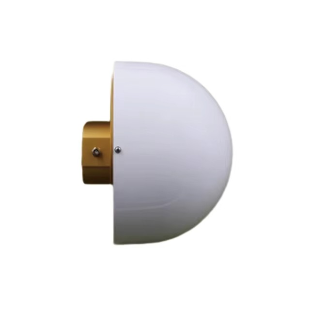
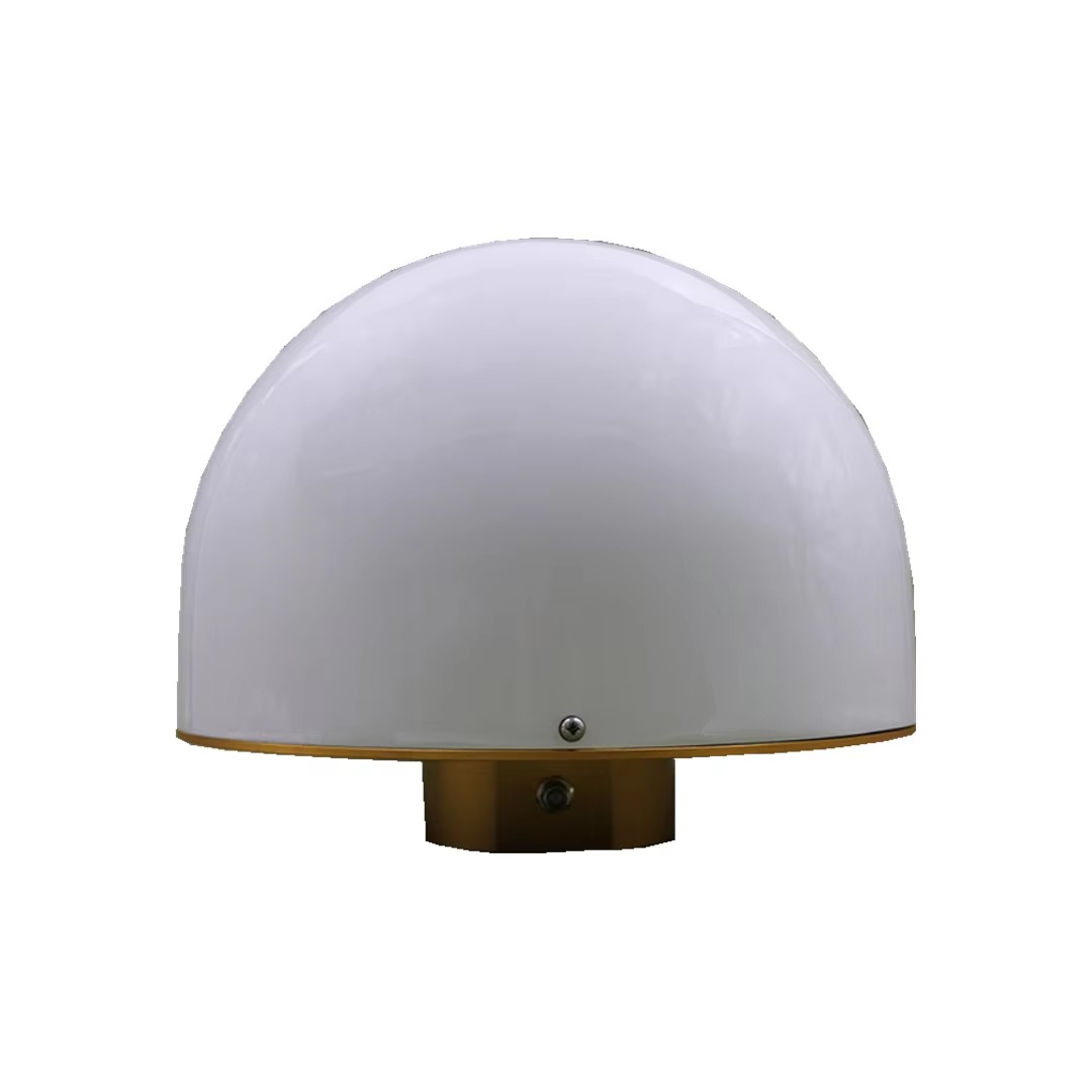
Traditional GNSS antennas struggle to distinguish between direct and reflected signals, as both carry the same satellite code and frequency. This is where the choke ring design proves revolutionary. A choke ring is a series of concentric metal rings mounted around the base of the antenna. These rings act as waveguides, absorbing or scattering multipath signals that approach the antenna from low angles (typically below 15 degrees), where reflections are most common. By suppressing these unwanted signals, the choke ring ensures that the antenna primarily receives direct, unaltered GNSS signals—laying the foundation for reliable RTK corrections.
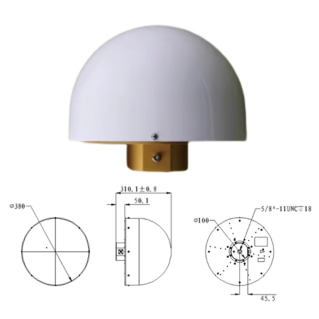
The GNSS RTK Full Band Choke Ring Antenna marries the multipath-mitigating power of a choke ring with the versatility of a full-band GNSS receiver. Its design is a testament to engineering precision, balancing signal reception, interference reduction, and compatibility with global satellite constellations. Let’s break down its core components and how they work in harmony:
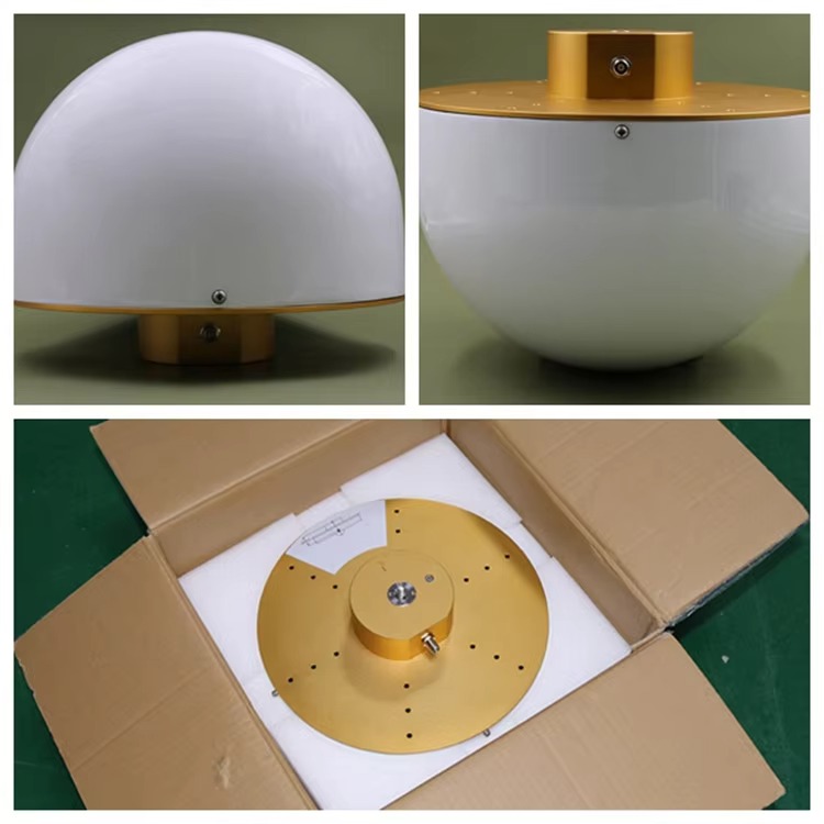
Choke Ring Structure: Anatomy of a Multipath Blocker
The choke ring itself is a series of circular metal rings, typically made from aluminum or copper, arranged concentrically around the antenna’s radiating element. The number of rings (usually 4 to 8) and their spacing are optimized to target low-angle reflections. When a multipath signal hits the rings, it induces currents in the metal, which generate opposing electromagnetic fields. These fields cancel out the reflected signal, preventing it from reaching the antenna’s receiver.
This design is particularly effective against ground reflections—a common issue in flat terrain, urban areas, or near water bodies. For example, in coastal surveying, where signals often reflect off the ocean surface, the choke ring can reduce multipath errors by up to 90%, ensuring that RTK corrections remain accurate even in challenging environments.
Full-Band GNSS Radiating Element: Capturing Signals Across Constellations
At the center of the choke ring assembly lies the antenna’s radiating element, engineered to receive signals across an extensive range of frequencies:
GPS: L1 (1575.42 MHz), L2 (1227.60 MHz), L5 (1176.45 MHz)
GLONASS: L1 (1602 MHz), L2 (1246 MHz)
BDS: B1 (1561.098 MHz), B2 (1207.14 MHz), B3 (1268.52 MHz)
Galileo: E1 (1575.42 MHz), E2 (1278.75 MHz), E5a (1176.45 MHz), E5b (1207.14 MHz)
This broad frequency coverage ensures that the antenna can leverage signals from multiple satellite constellations simultaneously. By combining data from GPS, GLONASS, BDS, and Galileo, the antenna reduces the risk of signal gaps caused by satellite availability or regional coverage limitations. For instance, in regions where GPS signals are weak, Galileo’s E5a/b or BDS’s B3 signals can serve as reliable alternatives, maintaining continuity in RTK data collection.
The radiating element is also designed with circular polarization, matching the polarization of GNSS signals (which rotate as they travel through the atmosphere). This alignment maximizes signal reception, even as the satellite’s position changes relative to the antenna.
The performance of the RTK Choke Ring Antenna is defined by a set of rigorous specifications, each contributing to its ability to deliver clean, reliable signals for RTK processing.
Axial Ratio at the Antenna Apex: Ensuring Polarization Efficiency
The axial ratio (AR) at the antenna apex is specified as ≤3 dB. Axial ratio measures how closely a polarized signal matches perfect circular polarization—a critical parameter for GNSS antennas, as satellite signals are circularly polarized. A low axial ratio (≤3 dB) indicates that the antenna efficiently captures these signals, even as their polarization shifts due to atmospheric effects or reflection.
In RTK applications, this efficiency is vital. A high axial ratio would cause signal attenuation, reducing the strength of incoming data and making it harder to distinguish between direct and multipath signals. By maintaining a low axial ratio, the antenna ensures that even weak signals (e.g., from satellites low on the horizon) are received with minimal loss, supporting robust RTK corrections.
Maximum Gain: Amplifying Signals Without Introducing Noise
The antenna boasts a maximum gain of ≥5.5 dBi for GNSS signals and ≥-1 dB for GSM900/GSM1800 bands. Gain measures the antenna’s ability to amplify signals in a specific direction relative to an isotropic antenna (a theoretical antenna that radiates equally in all directions).
For GNSS, a gain of ≥5.5 dBi ensures that faint satellite signals (which typically arrive at power levels of -130 dBm) are amplified to a level where the RTK receiver can process them effectively. This amplification is achieved using low-noise amplifiers (LNAs) integrated into the antenna, which boost signal strength without adding significant noise—critical for maintaining the signal-to-noise ratio (SNR) needed for precise timing measurements.
The GSM900/GSM1800 gain (≥-1 dB) may seem low, but it reflects the antenna’s dual role in RTK systems: not only receiving GNSS signals but also transmitting/receiving correction data via cellular networks. GSM bands are used to send raw GNSS data from the rover to the base station and receive real-time corrections. A gain of ≥-1 dB ensures that these cellular signals are transmitted with sufficient strength to reach nearby cell towers, even in remote areas, while avoiding over-amplification that could cause interference with the GNSS receiver.
Output Standing Wave Ratio (SWR): Optimizing Power Transfer
The output SWR is specified as ≤2.0. SWR measures the efficiency of power transfer between the antenna and the connected RTK receiver. A value of 1.0 indicates perfect impedance matching (no signal reflection), while higher values suggest that some power is reflected back, potentially causing signal loss or distortion.
For RTK systems, low SWR is critical because reflected power can corrupt the integrity of GNSS data, leading to errors in correction calculations. The antenna’s SWR ≤2.0 ensures that the majority of signal power is transferred to the receiver, minimizing losses and preserving the quality of the data used for positioning. This is particularly important in high-gain antennas, where even small reflections can amplify noise.
Impedance: Standardization for Seamless Integration
The antenna’s impedance is 50 ohms, a standard value in RF (radio frequency) systems, including GNSS receivers and coaxial cables. This standardization ensures compatibility with most RTK hardware, simplifying integration into existing systems. Mismatched impedance would create standing waves, reducing power transfer and introducing noise—both of which degrade RTK accuracy. By adhering to the 50-ohm standard, the antenna ensures that it can be paired with a wide range of receivers, base stations, and data loggers without compromising performance.
Working Voltage and Current: Efficiency for Field Operations
The antenna operates on a voltage range of 3~18 VDC and draws a maximum current of ≤40 mA. These parameters highlight its power efficiency—a key feature for RTK systems deployed in remote areas, where battery life is critical.
A wide voltage range (3~18 VDC) allows the antenna to be powered by various sources, from small lithium-ion batteries to vehicle-mounted power supplies, adding flexibility in field setups. The low current draw (≤40 mA) minimizes battery drain, extending the operational time of portable RTK rovers. For example, a survey team working in a remote forest can rely on the antenna to operate continuously for 12+ hours on a single battery charge, reducing the need for frequent recharging and maximizing productivity.
Joint Form: Secure Connections for Signal Integrity
The antenna uses MCX-KHD connectors for both GNSS and 4G (GSM) signals. MCX connectors are small, lightweight, and designed for high-frequency applications, offering a secure, threaded coupling mechanism that resists vibration and corrosion. This is critical for field operations, where equipment is often subjected to rough handling, extreme temperatures, and moisture. A loose or corroded connector can introduce signal loss or interference, disrupting RTK data collection. The MCX-KHD design ensures a reliable connection, even in harsh environments, preserving the integrity of both GNSS and cellular signals.
The RTK Choke Ring Antenna’s ability to mitigate multipath interference and leverage full-band GNSS signals makes it indispensable across a range of high-precision applications.
Land Surveying and Cadastral Mapping
Land surveyors require accurate measurements to define property boundaries, map terrain, and create legal land records. Multipath interference—from nearby buildings, trees, or water—has long been a challenge in this field, often leading to costly rework or disputes. The choke ring antenna eliminates these errors, allowing surveyors to collect data with centimeter-level accuracy in even the most complex environments.
For example, when surveying a coastal property with views of the ocean, traditional antennas would struggle with reflections off the water, introducing errors of 10+ centimeters. The RTK Choke Ring Antenna, however, suppresses these reflections, ensuring that boundary markers are placed with precision, reducing the risk of legal disputes and streamlining land registration.
Construction and Infrastructure Layout
In construction, precise positioning is critical for laying foundations, aligning structural elements, and ensuring compliance with design specifications. A single centimeter of error in foundation layout can lead to costly delays or safety hazards in high-rise buildings, bridges, or tunnels. The RTK Choke Ring Antenna, with its multipath mitigation, ensures that construction teams can stake out positions with confidence, even in urban environments where reflections from nearby buildings are common.
For instance, when building a skyscraper in a dense city center, the antenna’s choke ring suppresses signals reflecting off adjacent structures, allowing the RTK system to maintain centimeter-level accuracy. This ensures that steel beams, elevator shafts, and utility lines are aligned exactly as engineered, minimizing rework and ensuring structural integrity.
Geodesy and Scientific Research
Geodetic studies, which measure the Earth’s shape, rotation, and gravitational field, require millimeter-level precision over long periods. These studies are critical for understanding tectonic plate movement, sea-level rise, and natural hazards like earthquakes. The RTK Choke Ring Antenna is a staple in geodetic networks, as its ability to filter multipath signals ensures consistent, long-term data accuracy.
In volcanic monitoring, for example, scientists use RTK-equipped stations to track minute changes in a volcano’s shape—indicators of magma movement. The choke ring antenna ensures that these measurements are not corrupted by reflections off lava flows or surrounding terrain, providing early warning of potential eruptions.
Autonomous Vehicle Testing
The development of autonomous vehicles (AVs) relies on precise, real-time positioning to ensure safe navigation. AVs require centimeter-level accuracy to detect lane lines, avoid obstacles, and interact with other vehicles. In testing environments, where AVs operate in complex scenarios (e.g., near buildings, under bridges, or on tree-lined roads), multipath interference can disrupt positioning data, leading to incorrect decisions.
The RTK Choke Ring Antenna solves this problem by suppressing reflections, providing AVs with reliable positioning data even in challenging environments. This accelerates testing and ensures that AVs can safely transition from controlled environments to real-world roads.
Advancements in Choke Ring Technology: Future Trends
While the RTK Choke Ring Antenna is already a pinnacle of precision, ongoing advancements continue to enhance its performance:
Miniaturization: Traditional choke rings are bulky, making them impractical for portable applications. New designs use lightweight materials (e.g., carbon fiber) and optimized ring geometries to reduce size and weight without sacrificing multipath mitigation. This allows the antenna to be integrated into smaller RTK rovers, drones, and handheld devices.
Adaptive Filtering: Some modern choke ring antennas incorporate software-defined radios (SDRs) that dynamically adjust to environmental conditions. For example, if the antenna detects increased reflections from a nearby building, it can adjust its filtering parameters to target those specific angles, further reducing interference.
Dual-Band Choke Rings: To address the growing use of higher-frequency GNSS bands (e.g., GPS L5, Galileo E5), new choke rings are optimized for both low and high frequencies, ensuring consistent performance across the full spectrum of GNSS signals.
The GNSS RTK Full Band Choke Ring Antenna represents the convergence of advanced engineering and practical necessity, solving the longstanding challenge of multipath interference in high-precision positioning. By combining a full-band GNSS receiver with a specialized choke ring design, it delivers clean, reliable signals that enable RTK systems to achieve centimeter-level accuracy in even the most challenging environments.
From land surveying and construction to scientific research and autonomous mobility, this antenna is transforming industries by providing the precision needed to drive innovation, efficiency, and safety. As technology continues to advance, the RTK Choke Ring Antenna will remain a cornerstone of geospatial measurement, ensuring that our ability to map, build, and navigate the world is limited only by our imagination—not by signal interference. For professionals who demand the highest level of accuracy, this antenna is more than a tool; it is a guarantee of reliability in an unpredictable world.

 86 0755 2819 9597
Lucy Yang | lucy.y@toxutech.com
Nicole Li | nicole@toxutech.com
Dotty Zhao | sales04@toxutech.com
Global Business Director / Sales Team / Global Operations


 En
En Cn
Cn Korean
 Home >


